

Page 1
Bedienungsanleitung
Operating instructions
Notice utilisateurs
Strömungswächter
Flow monitor
Contrôleur de débit
SID
701935 / 01 07 / 2010
DEUTSCHENGLISHFRANÇAIS
R
Page 2
2
Weitere Einstellmöglichkeiten (→ Seite 9)
• Der HI-Abgleich genügt für die meisten wasserbasierten
Applikationen. Optional: auf Minimalströmung abgleichen (LO-
Abgleich).
• Schaltpunkt einstellen (zur Veränderung der Reaktionszeit und
der Betriebsreserve).
• Einstellung zur Überwachung und optischen Anzeige von
Überströmung.
• Aktivieren / Deaktivieren der Funktion Fernabgleich.
• Rücksetzen auf Werkseinstellung.
• Installieren
Montage → Seite 6, elektrischer Anschluß → Seite 8.
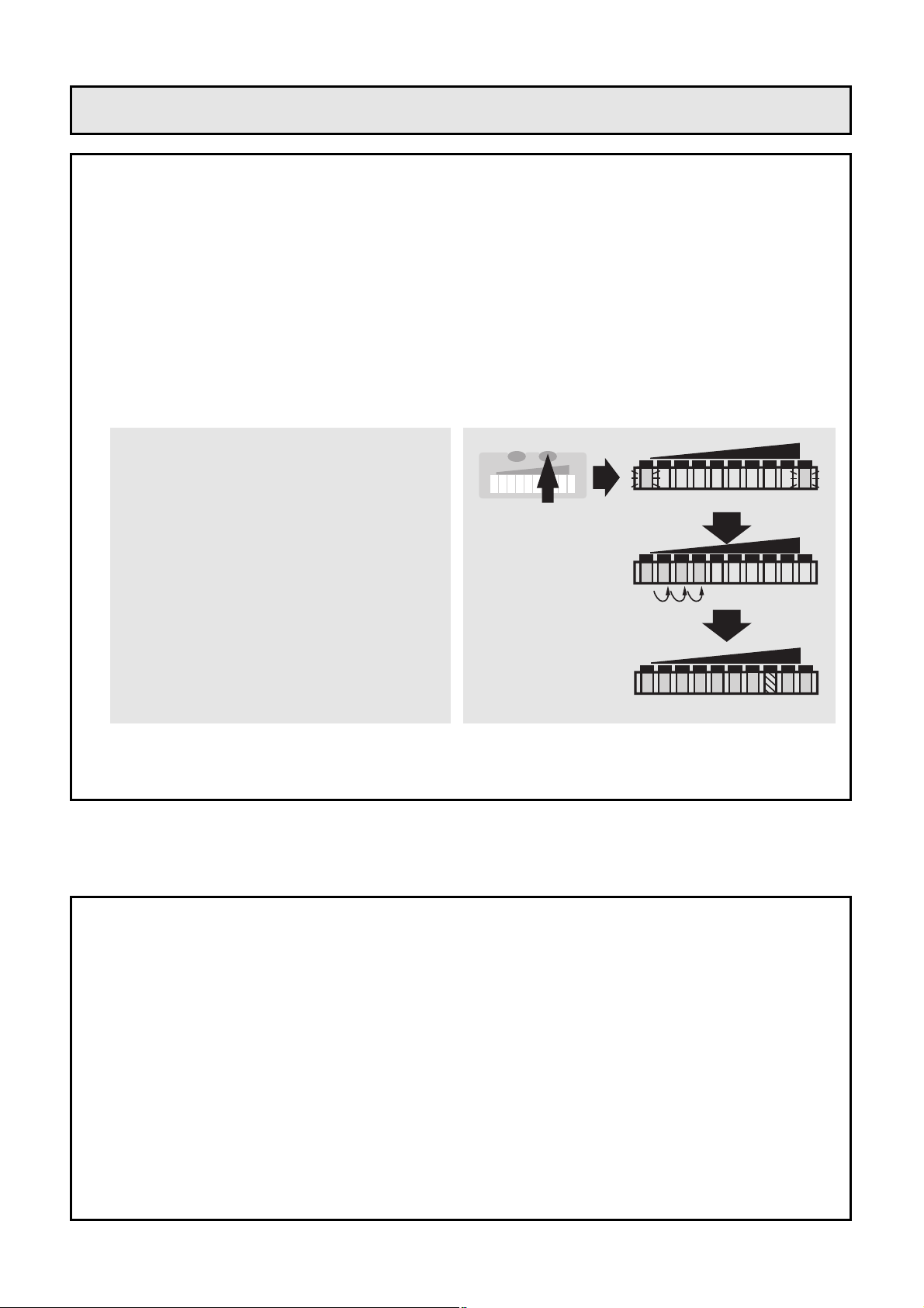
• HI-Abgleich
Schalten Sie die Betriebsspannung ein.
Nach etwa 15s ist das Gerät betriebsbereit.
Lassen Sie das Medium mit der gewünschten Maximal-
strömung (HI) in der Anlage fließen.
• Das Gerät ist betriebsbereit.
Drücken Sie die Taste Learn/Set
und halten Sie sie gedrückt.
Die grünen LEDs rechts und links
blinken,
nach 5s füllt sich der LED-Balken
(grün) von links nach rechts
(lassen Sie die Taste los, sobald
die ersten LEDs leuchten).
Die Anzeige verlischt kurzzeitig.
Das Gerät speichert die aktuelle
Strömung als Maximalströmung.
LO HI
LO HI
HILO
>5...<10
M
S
Kurzanleitung
Page 3
DEUTSCH
3
MODE /
ENTER
2468
LEARN /
SET
103579
LO HI
FLOW RATE
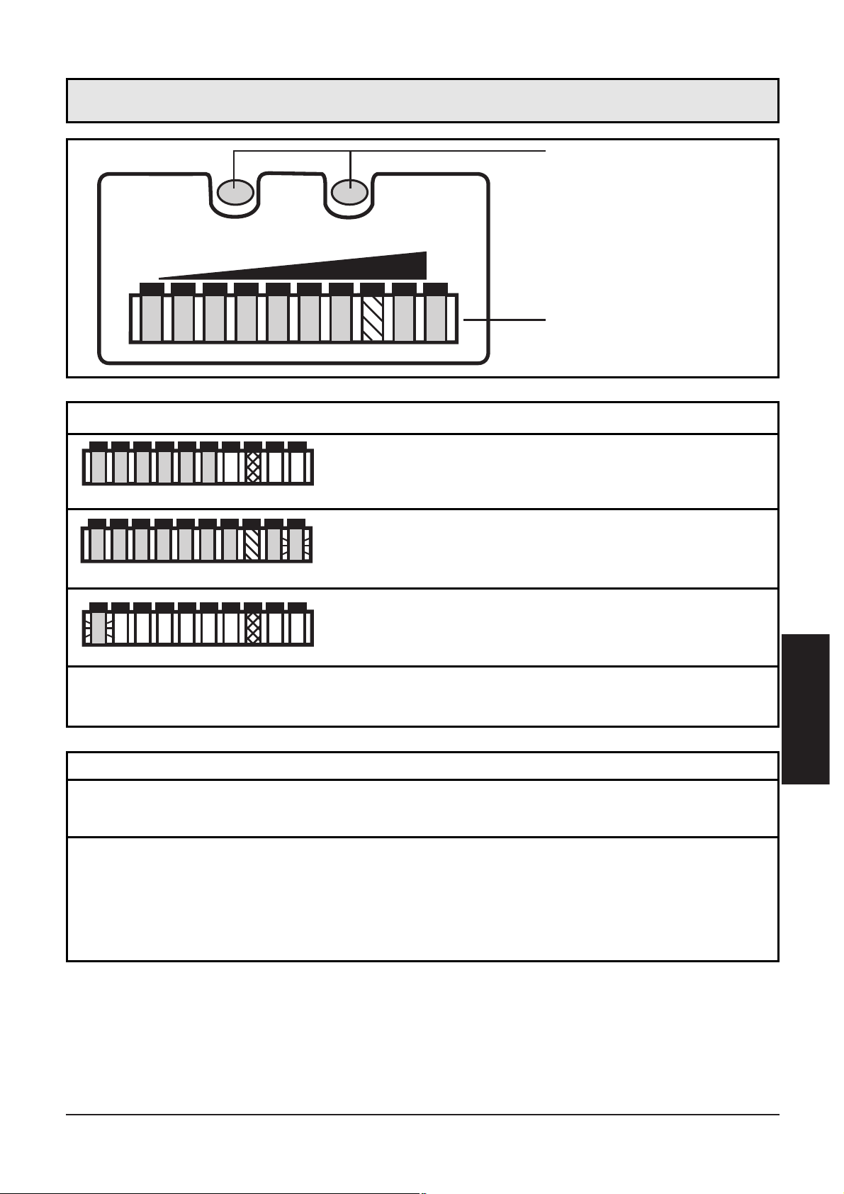
Einstelltasten
Aktuelle Strömung im Anzeigebereich
(grüner LED-Balken)
Anzeige des Schaltpunkts (SP):
LED orange: Strömung ≥ SP; LED rot: Strömung < SP
Betriebsanzeige (Run-Modus)
Überströmung (LED 9 blinkt)
Unterströmung (LED 0 blinkt)
Betriebsanzeige
2468103579
2468103579
Bedien- und Anzeigeelemente
Mode / Enter:
• Anwahl der Menüpunkte und Bestätigung
Learn/Set:
• Abgleich auf Maximal- / Minimalströmung;
• Reset (Werkseinstellung wieder herstellen);
• Einstellen von Werten
(kontinuierlich durch Dauerdruck; schrittweise durch Einzeldruck)
Einstelltasten
Page 4
4
2468103579
LO
HI
1x
>5s
1x
2x
5s
1x
...
3x
> 5s
1x
>5...<10s
>10...<15s
>15...<20s
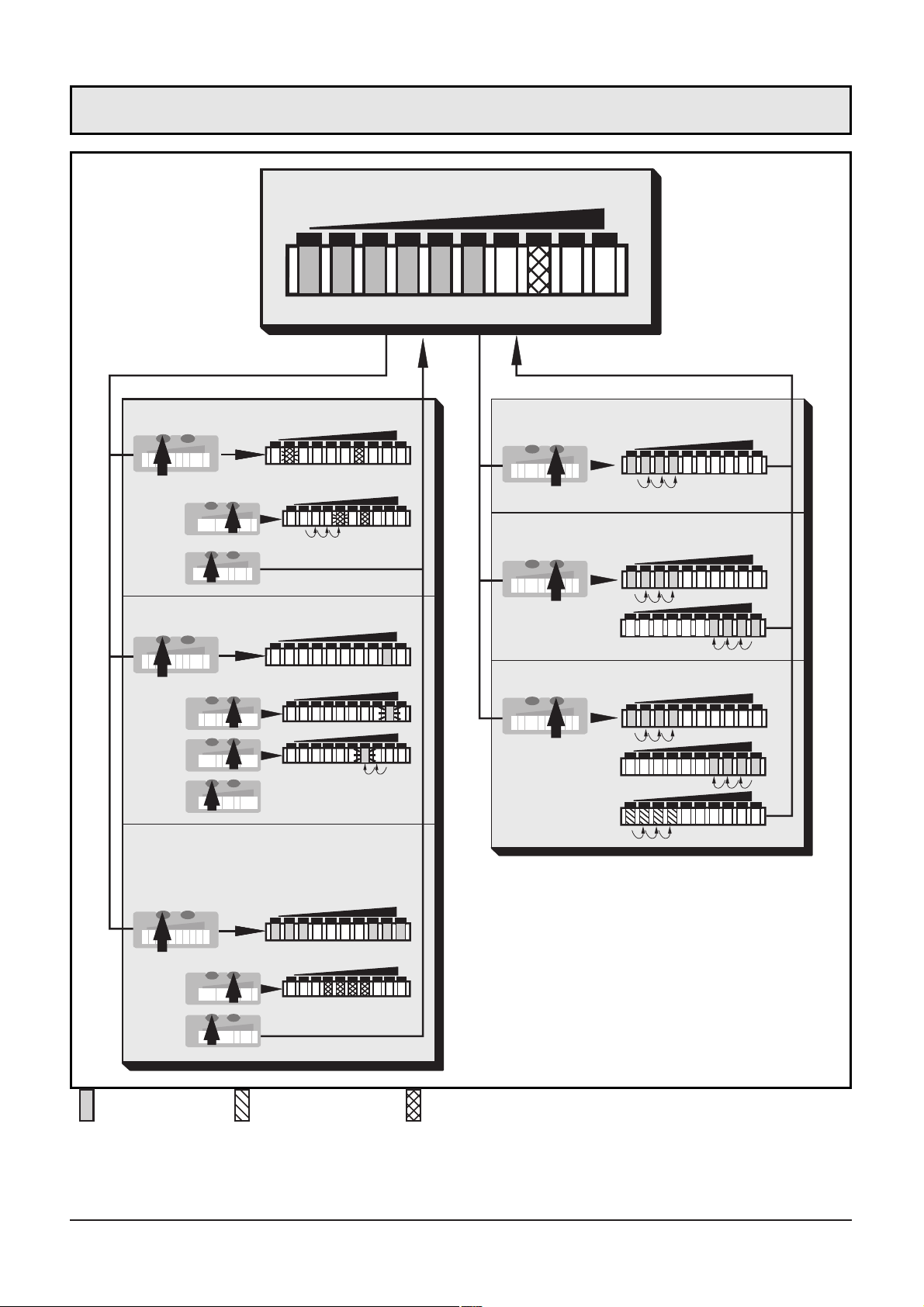
Abgleich Minimalströmung
Abgleich Maximalströmung
Gerätefunktionen
(ENTER-Taste)
Abgleich /
Werkseinstellung
(SET-Taste)
Überwachung Überströmung
Schaltpunkt einstellen
Fernabgleich deaktivieren /
aktivieren
Run-Modus
LED = grün LED = orange LED = rot
Menüstruktur
Rücksetzen Werkseinstellung
Page 5
Der Strömungswächter
• erfaßt die Strömungsgeschwindigkeit in flüssigen und gasförmi-
gen Medien,
• schaltet den Ausgang entsprechend der Programmierung
(Schließer oder Öffner, programmierbar durch Anschlußbelegung;
→ Seite 8),
• zeigt den relativen Strömungswert innerhalb des einstellbaren
Erfassungsbereichs durch ein LED-Display an
- LED 0 = unteres Ende des Fensters (Minimalwert / LO)
- LED 9 = oberes Ende des Fensters (Maximalwert / HI).
• Zusätzlich können angezeigt werden:
- Schaltzustand (LED rot: Strömung unterhalb des Schaltpunkts;
LED orange: Strömung hat Schaltpunkt erreicht).
- Überströmung: LED 9 blinkt, wenn die Strömung 2 LEDs über der
Maximalströmung liegt.
- Unterströmung / Strömungsstillstand: LED 0 blinkt, wenn die
Strömung unter der Minimalströmung liegt.
DEUTSCH
5
Bestimmungsgemäße Verwendung
Inhalt
Bestimmungsgemäße Verwendung . . . . . . . . . . . . . . . . . . . Seite 5
Montage . . . . . . . . . . . . . . . . . . . . . . . . . . . . . . . . . . . . . . Seite 6
Elektrischer Anschluß . . . . . . . . . . . . . . . . . . . . . . . . . . . . . Seite 8
Programmieren . . . . . . . . . . . . . . . . . . . . . . . . . . . . . . . . . Seite 9
Inbetriebnahme / Betrieb / Wartung . . . . . . . . . . . . . . . . . Seite 11
Technische Daten . . . . . . . . . . . . . . . . . . . . . . . . . . . . . . . Seite 11
Einstelldiagramme / Technik-Information . . . . . . . . . . . . . . Seite 12
Page 6
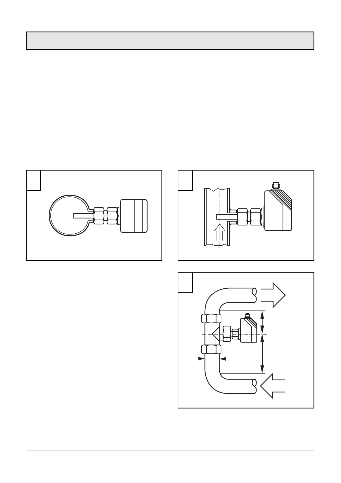
Das Gerät ist adaptierbar an unterschiedliche Prozeßanschlüsse.
(Adapter sind gesondert als Zubehör zu bestellen).
• Montieren Sie das Gerät bei waagerecht verlaufenden Rohren
möglichst seitlich (Abb 1).
Bei Montage von unten sollte die Rohrleitung frei von
Ablagerungen sein.
Bei Montage von oben sollte die Rohrleitung vollständig mit dem zu
überwachenden Medium gefüllt sein.
• Montieren Sie das Gerät bei senkrecht verlaufenden Rohren in der
Steigleitung (Medium strömt aufwärts, Abb. 2).
Um Fehlfunktionen zu vermeiden, müssen Mindestabstände
zwischen Sensor und
Krümmungen, Ventilen,
Reduzierungen u. ä. eingehalten
werden.
• Mindestens 5 mal Rohrdurchmesser an der Anströmseite
(A).
• Mindestens 3 mal Rohrdurchmesser an der Abströmseite
(B).
6
Montage
D
A
B
min.
5 x D
min.
3 x D
1 2
3
Page 7

1. Fetten Sie die Überwurfmutter (3) und alle Gewinde mit Schmierpaste ein, um mehrmaliges Lösen und Festziehen zu gewährleisten.
Achtung: Es darf kein Fett auf die Sensorspitze (A) gelangen.
2. Schrauben Sie den passenden Adapter (2) auf den Prozeßanschluß (1).
3. Setzen Sie den Strömungswächter auf den Adapter und ziehen Sie
die Überwurfmutter (3) an; (Anzugsdrehmoment max. 50Nm).
Halten Sie dabei das Gerät in seiner Ausrichtung.
Eintauchtiefe des Sensors: mindestens 12mm in der Rohrleitung.
Bei Verwendung der als Zubehör lieferbaren Adapter ist die korrekte
Eintauchtiefe sichergestellt.
Achtung: Die Sensorspitze darf die Rohrwand nicht berühren.
DEUTSCH
7
1 2 3
⎩
⎨
⎧
A
Gewinde M18 x 1,5
27
13,52713,5
35
21
Montagemaß mit
M12-Adapter
Montagemaß mit
G¼-Adapter
Montagemaß mit
G½-Adapter
Page 8
Das Gerät darf nur von einer Elektrofachkraft installiert werden.
Befolgen Sie die nationalen und internationalen Vorschriften zur
Errichtung elektrotechnischer Anlagen.
Spannungsversorgung nach EN50178, SELV, PELV.
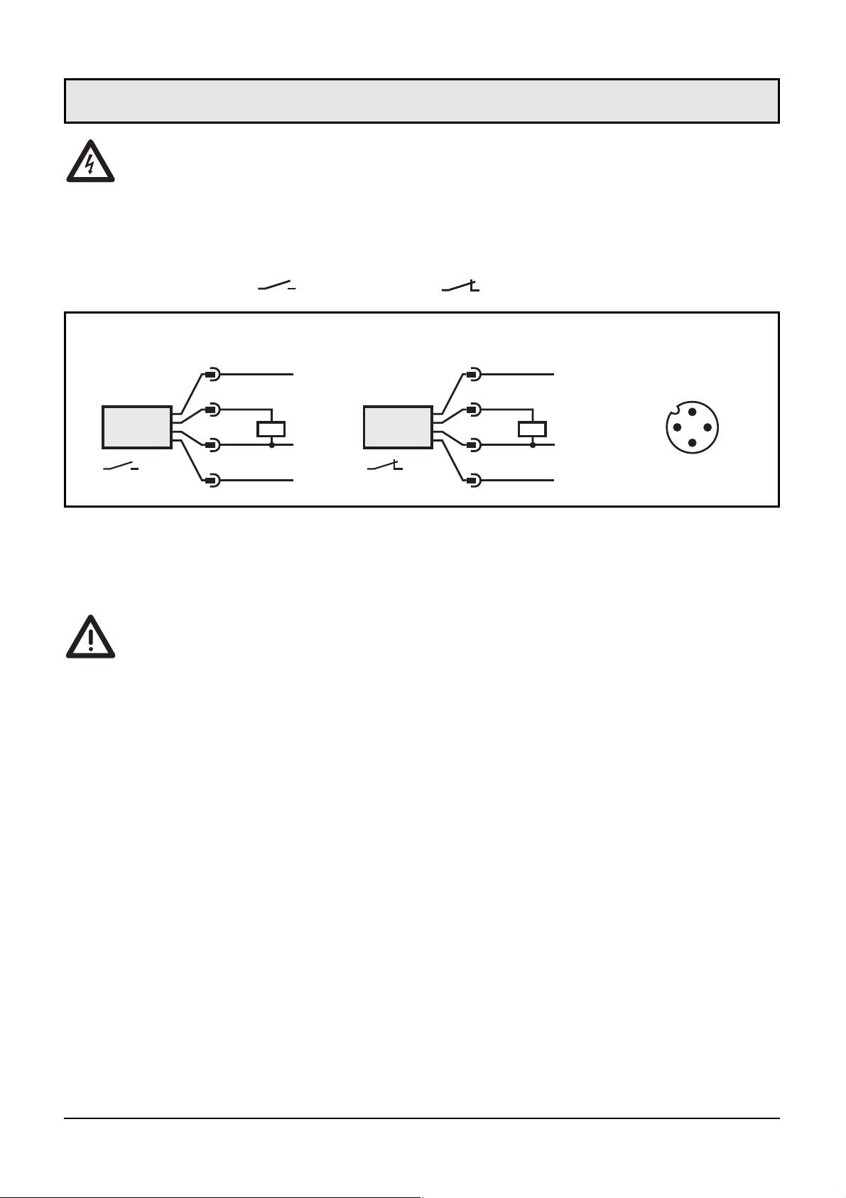
Schalten Sie die Anlage spannungsfrei und schließen Sie das Gerät folgendermaßen an ( = Schließer / = Öffner):
Wenn die Funktion Fernabgleich aktiv ist:
Verwenden Sie 4-Draht-Kabeldosen ohne Brücke zwischen Pins 2 und 4.
Bei 3-Draht-Kabeldosen mit Brücke zwischen Pin 2 und Pin 4 löst das
Einschalten der Endstufe den Fernabgleich aus!
Störanzeige: Bei Kurzschluß leuchten Betriebsanzeige und rote LEDKette im Wechsel.
8
Elektrischer Anschluß
P
L
+
2
1
4
3
L-
P
L
+
2
3
4
1
L-
3
1
4
2
WH
BU
BK
BN
WH
BN
BK
BU
P = Programmierleitung (für Fernabgleich)
Adernfarben bei ifm-Kabeldosen:
1 = BN (braun), 2 = WH (weiß), 3 = BU (blau), 4 = BK (schwarz)
Steckeransicht
(am Gerät)
Page 9
9
■■
Überwachungsbereich Strömung einstellen
HI-Abgleich
• Medium mit gewünschter Maximalströmung in der Anlage fließen
lassen.
• >5...<10s lang Taste Learn/Set drücken (= Abgleich auf
Maximalströmung / oberes Ende des Überwachungsbereichs).
Optional: LO-Abgleich
Der HI-Abgleich genügt für die meisten wasserbasierten
Applikationen. Zusätzlich können Sie das Gerät in einem zweiten
Schritt auf Minimalströmung abgleichen:
• Medium mit gewünschter Minimalströmung in der Anlage fließen
lassen bzw. Strömung anhalten.
• >10...<15s lang Taste Learn/Set drücken (= Abgleich auf
Minimalströmung oder Strömungsstillstand / unteres Ende des
Über-wachungsbereichs).
■■
Fernabgleich über Programmierleitung
Für die jeweilige Zeit Betriebsspannung (+U
B
) an Pin 2 (P) anlegen.
■■
Schaltpunkt einstellen
• 1 x kurz Taste Mode/Enter drücken.
• 5s lang Taste Learn/Set drücken.
• Taste Learn/Set festhalten oder mehrmals drücken, bis gewünschter
Schaltpunkt eingestellt ist.
• 1 x kurz Taste Mode/Enter drücken.
■■
Überwachung auf Überströmung
• 2 x kurz Taste Mode/Enter drücken.
• 5s lang Taste Learn/Set drücken, loslassen, wenn LED blinkt.
• Taste Learn/Set mehrmals drücken, um die LED für den oberen
Anzeigewert der Betriebsströmung zu verschieben.
• 1 x kurz Taste Mode/Enter drücken.
Programmieren
Page 10

■■
Aktivieren / Deaktivieren der Funktion Fernabgleich
• 3 x kurz Taste Mode/Enter drücken.
• 5s lang Taste Learn/Set drücken.
• Taste Learn/Set festhalten oder mehrmals drücken, bis gewünschte
Funktion eingestellt ist (Funktion aktiv, wenn rechts und links je
3 LEDs grün leuchten; Funktion nicht aktiv, wenn 4 LEDs in der
Mitte der Anzeige rot leuchten).
• 1 x kurz Taste Mode/Enter drücken.
■■
Werkseinstellung wieder herstellen
• >15...<20s lang Taste Learn/Set drücken.
■■
Für die Einstellvorgänge gilt:
• Wird während des Einstellvorgangs 15s lang keine Taste gedrückt,
geht das Gerät mit unveränderten Werten in den Betriebsmodus
zurück.
• Ist der Abgleich nicht möglich, blinken alle roten LEDs. Danach geht
das Gerät mit unveränderten Werten in den Betriebsmodus zurück.
■■
Verriegeln / Entriegeln
Das Gerät läßt sich verriegeln, so daß unbeabsichtigte Fehleingaben
verhindert werden: Drücken Sie im Run-Modus 10s lang die beiden
Einstelltasten. Sobald die Anzeige verlischt, ist das Gerät verriegelt
oder entriegelt. Auslieferungszustand: Nicht verriegelt.
Ist das Gerät verriegelt, kann angezeigt werden:
• Der aktuelle Schaltpunkt (Taste Mode/Enter 1 x drücken).
• Aktuelle Einstellung für Überwachung auf Überströmung (Taste
Mode/Enter 2 x drücken).
• Die Einstellung der Funktion Fernabgleich (Taste Mode/Enter 3 x
drücken).
10
Page 11
11
Prüfen Sie nach Montage, elektrischem Anschluß und
Programmierung, ob das Gerät sicher funktioniert. Nach dem
Einschalten der Versorgungsspannung leuchten alle LEDs auf und verlöschen wieder schrittweise.* Danach ist das Gerät betriebsbereit.
*Während dieser Zeit ist der Ausgang entsprechend der Programmierung
geschaltet: EIN bei Schließerfunktion und AUS bei Öffnerfunktion.
Störanzeige: Bei Kurzschluß leuchten Betriebsanzeige und roter LEDBalken im Wechsel.
Wartungsempfehlung: Überprüfen Sie die Sensorspitze von Zeit zu
Zeit auf Ablagerungen. Reinigen Sie sie gegebenenfalls mit einem weichen Tuch. Fest anhaftende Ablagerungen (z. B. Kalk) lassen sich mit
handelsüblichem Essigreiniger entfernen.
Technische Daten
DEUTSCH
Inbetriebnahme / Betrieb / Wartung
Betriebsspannung [V] . . . . . . . . . . . . . . . . . . . . . . . . . . . . . . 20 ... 36 DC
1
Strombelastbarkeit [mA] . . . . . . . . . . . . . . 400; Kurzschlußschutz, getaktet;
verpolungssicher / überlastfest
Spannungsabfall [V] . . . . . . . . . . . . . . . . . . . . . . . . . . . . . . . . . . . . . < 2,5
Stromaufnahme [mA] . . . . . . . . . . . . . . . . . . . . . . . . . . . . . . . . . . . . < 80
Flüssige Medien
Mediumtemperatur [°C]. . . . . . . . . . . . . . . . . . . . . . . . . . . . . . . -25 ... +80
Einstellbereich [cm/s]. . . . . . . . . . . . . . . . . . . . . . . . . . . . . . . . . . . 3 ... 300
Größte Empfindlichkeit [cm/s] . . . . . . . . . . . . . . . . . . . . . . . . . . . . . 3 ... 60
Temperaturgradient [K/min] . . . . . . . . . . . . . . . . . . . . . . . . . . . . . . . . . 300
Gasförmige Medien
Mediumtemperatur [°C]. . . . . . . . . . . . . . . . . . . . . . . . . . . . . . . -25 ... +80
Einstellbereich [cm/s]. . . . . . . . . . . . . . . . . . . . . . . . . . . . . . . . 200 ... 3000
Größte Empfindlichkeit [cm/s] . . . . . . . . . . . . . . . . . . . . . . . . . . 200 ... 800
Ansprechzeit [s] . . . . . . . . . . . . . . . . . . . . . . . . . . . . . . . . . . . . . . . 1 ... 10
Bereitschaftsverzögerungszeit [s] . . . . . . . . . . . . . . . . 15, optisch signalisiert
Druckfestigkeit [bar] . . . . . . . . . . . . . . . . . . . . . . . . . . . . . . . . . . . . . . 300
Umgebungstemperatur [°C] . . . . . . . . . . . . . . . . . . . . . . . . . . . . -25 ... +80
Schutzart . . . . . . . . . . . . . . . . . . . . . . . . . . . . . IP 67 (IEC60529) / (UL50)
Schockfestigkeit [g] . . . . . . . . . . . . . . . . . . . . 50 (DIN / IEC 68-2-27, 11 ms)
Vibrationsfestigkeit [g] . . . . . . . . . . . . . . 20 (DIN / IEC 68-2-6, 55-2000 Hz)
Gehäusewerkstoffe . . . . . . . . . . . . . . . . . . . . . . . . . . . . . . . . . . PBT-GF 20
Sensorwerkstoff (SI10xx) . . V4A (1.4404); O-Ring: FPM 8x1,5 gr 80° Shore A
Sensorwerkstoff (SI11xx) . Titan (3.7035); O-Ring: FPM 8x1,5 gr 80° Shore A
1)
nach EN50178, SELV, PELV
Page 12
■■
Überwachungsbereich Strömung einstellen
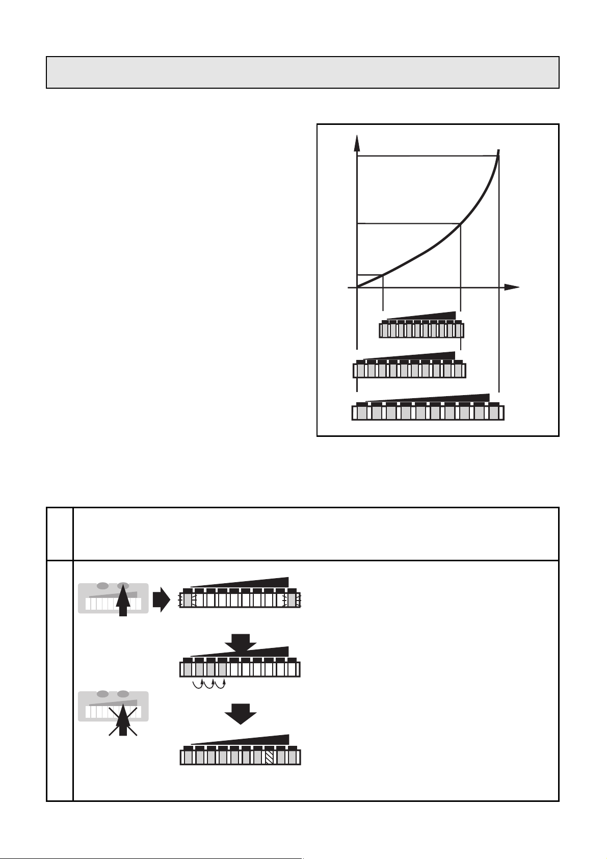
Der Erfassungsbereich (Fenster)
wird festgelegt durch
• Abgleich auf gewünschte
Maximalströmung (HI-Teach)
= oberes Ende des Fensters.
Dieser Abgleich genügt für die
meisten wasserbasierten
Applikationen.
• Zusätzlich Abgleich auf
gewünschte Minimalströmung /
Strömungsstillstand (LO-Teach)
= unteres Ende des Fensters
(optional).
• Abgleich auf Maximalströmung (HI-Teach)
Das Gerät erfaßt die vorhandene Strömung und setzt diesen Wert als
oberen Anzeigewert für das LED-Display (LED 9).
12
1
2
Drücken Sie die Taste Learn/Set
und halten Sie sie gedrückt.
Die grünen LEDs rechts und links
blinken,
nach 5s füllt sich der LED-Balken
(grün) von links nach rechts
(lassen Sie die Taste los, sobald
die ersten LEDs leuchten).
Die Anzeige verlischt kurzzeitig.
Das Gerät speichert die aktuelle
Strömung als Maximalströmung
und geht in den Betriebsmodus.
LO HI
LO HI
HILO
>5...<10s
M
S
Schalten Sie die Betriebsspannung ein. Nach etwa 15s ist das Gerät
betriebsbereit. Lassen Sie das Medium mit der gewünschten
Maximalströmung in der Anlage fließen.
Einstelldiagramme / Technik-Information
2468103579
LO HI
2468103579
LO HI
2468103579
LO HI
0
Strömungs-
geschwindigkeit
Sensorsignal
M
S
Page 13
13
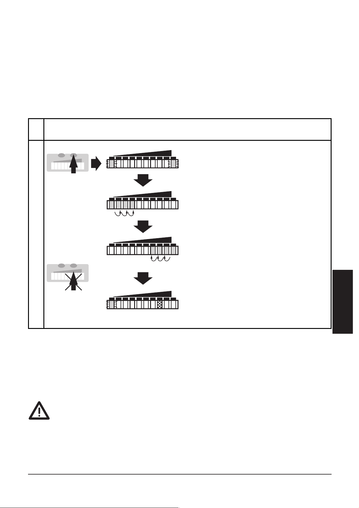
• Abgleich auf Minimalströmung / Strömungsstillstand
(LO-Teach), optional
Das Gerät erfaßt die vorhandene Strömung und setzt diesen Wert als
unteren Anzeigewert für das LED-Display. Im Betriebszustand blinkt
die erste grüne LED (LED 0), wenn die Strömung unter diesen Wert
fällt (bzw. wenn Strömungsstillstand eintritt).
ACHTUNG: LO-Teach darf nur nach HI-Teach durchgeführt werden.
• Fernabgleich
Sie können das Gerät auch über die Programmierleitung abgleichen,
wenn die Funktion Fernabgleich aktiv ist. Legen Sie für die jeweilige
Zeit Betriebsspannung (+U
B
) an Pin 2 (P):
>5...<10s
für HI-Teach,
>10...<15
s für LO-Teach.
DEUTSCH
Wenn die Betriebsspannung länger als 15s Pin 2 anliegt,
• werden alle Einstellungen auf Werkseinstellung zurückgesetzt.
Wenn die Betriebsspannung länger als 20s an Pin 2 anliegt,
• bleibt der Abgleich unwirksam; das Gerät geht mit unveränderten
Werten in den Betriebsmodus;
• wird das Gerät verriegelt (die Tastenfunktionen sind so lange
gesperrt, wie die Betriebsspannung an Pin 2 anliegt).
1
2
Drücken Sie die Taste Learn/Set
und halten Sie sie gedrückt.
Die grünen LEDs rechts und links
blinken,
nach 5s füllt sich der LED-Balken
(grün) von links nach rechts,
nach weiteren 5s füllt sich der
LED-Balken (grün) von rechts
nach links
(lassen Sie die Taste los, sobald
die ersten LEDs rechts leuchten).
Die Anzeige verlischt kurzzeitig.
Das Gerät speichert die aktuelle
Strömung als Minimalströmung
und geht in den Betriebsmodus.
LO HI
LO HI
HILO
LO HI
>10...<15s
M
S
Lassen Sie das Medium mit der gewünschten Minimalströmung
in der Anlage fließen bzw. halten Sie die Strömung an.
M
S
Page 14
14
■■
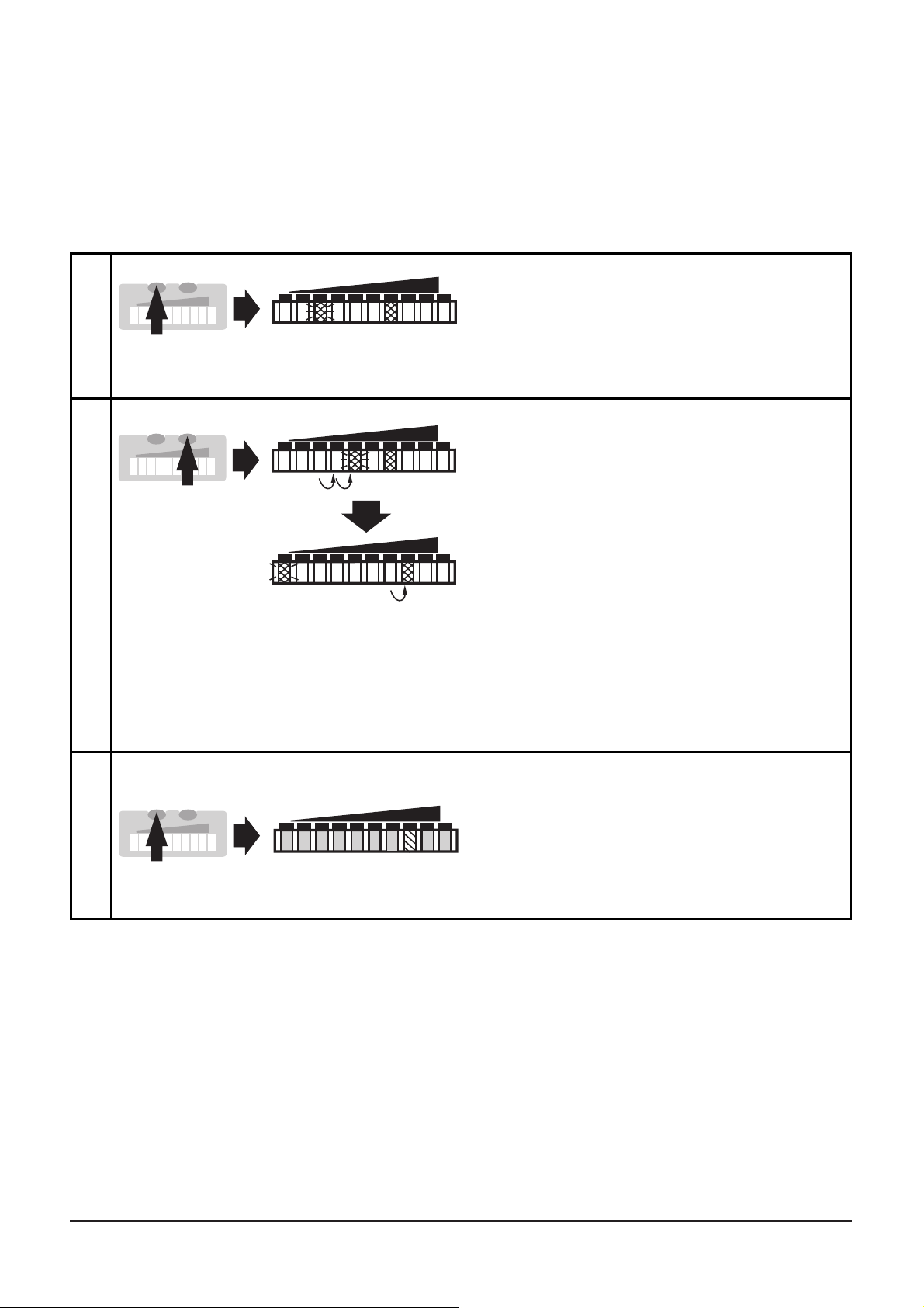
Schaltpunkt einstellen
Der Schaltpunkt ist werksseitig voreingestellt (LED 7). Die Einstellung
beeinflußt die Reaktionszeit des Geräts:
• Hoher Schaltpunkt = schnelle Reaktion bei Strömungsabfall,
• niedriger Schaltpunkt = schnelle Reaktion bei Strömungsanstieg.
*Schaltpunkt verringern: Lassen Sie blinkende und leuchtende LED bis zum
maximalen Einstellwert laufen. Danach beginnt der Durchlauf wieder bei
dem minimalen Einstellwert.
**Überlauf: Überschreiten blinkende und leuchtende LEDs den maximalen
Einstellwert, beginnt der Durchlauf wieder bei dem minimalen Einstellwert.
1
2
Drücken Sie die Taste Mode/Enter
einmal. Der aktuelle Schaltpunkt
wird angezeigt:
Leuchtende LED: Grobeinstellung,
blinkende LED: Feineinstellung.
Drücken Sie die Taste Learn/Set
und halten Sie sie gedrückt.
Nach 5s wird der Schaltpunkt
erhöht* (schrittweise durch
Einzeldruck oder kontinuierlich
durch Festhalten der Taste).
Anzeige:
Die blinkende LED läuft von links
nach rechts. Nach Erreichen der
LED 9 beginnt der Durchlauf
wieder bei LED 0. Die stetig
leuchtende LED wandert eine
Position weiter.**
LO HI
LO HI
LO HI
1 x
M
S
M
S
3
Drücken Sie kurz die Taste
Mode/Enter (= Bestätigung).
Die Anzeige verlischt kurzzeitig.
Der eingestellte Schaltpunkt wird
wirksam; das Gerät geht in den
Betriebsmodus.
HILO
M
S
>5s
Page 15
15
■■
Überwachung auf Überströmung
Mit dieser Funktion können Sie die Position des Anzeigefensters im
Überwachungsbereich festlegen: Verschieben Sie die LED für den oberen Anzeigewert auf die Position 8, 7, 6 oder 5. Bei maximaler
Betriebsströmung leuchten alle LEDs von 0 bis zu dieser LED. Die LEDs
oberhalb dieses Bereichs signalisieren Überströmung.
Liegt der Schaltpunkt oberhalb des Bereichs, schaltet das Gerät bei
Überströmung.
Hinweis:
Nach jedem Abgleich auf Maximalströmung (HI-Teach) wird die Verschiebung
wieder zurückgesetzt (auf LED 9).
DEUTSCH
1
2
Drücken Sie die Taste
Mode/Enter zweimal.
Die aktuelle Einstellung wird
angezeigt (grüne LED).
Drücken Sie die Taste Learn/Set
5 s lang (bis die LED blinkt).
LO HI
LO HI
2 x
M
S
M
S
3
Drücken Sie die Taste Learn/Set
so oft, bis die gewünschte LED
blinkt.
Bei jedem Tastendruck geht die
LED eine Position zurück. Bei
Unterschreiten der LED 5 beginnt
der Durchlauf wieder bei LED 9.
LO HI
M
S
4
Drücken Sie kurz die Taste
Mode/Enter (= Bestätigung).
Die Anzeige verlischt kurzzeitig.
Das Gerät speichert die neue
Einstellung und geht in den
Betriebsmodus.
HI
LO
M
S
5s
Page 16
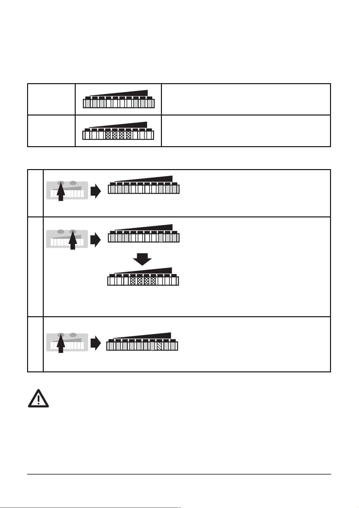
■■
Aktivieren / Deaktivieren der Funktion Fernabgleich
Ist die Funktion aktiv, kann das Gerät durch Spannung auf Pin 2 abgeglichen werden.
Auslieferungszustand: Funktion aktiv.
Wenn die Funktion Fernabgleich aktiv ist, und die Betriebsspannung
länger als 20s an Pin 2 anliegt, wird das Gerät verriegelt (die Tastenfunktionen sind so lange gesperrt, wie die Betriebsspannung an Pin 2
anliegt).
Verwenden Sie 4-Draht-Kabeldosen ohne Brücke zwischen Pins 2 und 4.
Bei 3-Draht-Kabeldosen mit Brücke zwischen Pin 2 und Pin 4 löst das
Einschalten der Endstufe den Fernabgleich aus!
16
Funktion
nicht aktiv
Die 4 LEDs in der Mitte leuchten rot.*
LO HI
Funktion
aktiv
Rechts und links leuchten je 3 LEDs grün.*
HILO
1
2
Drücken Sie die Taste
Mode/Enter dreimal.
Die aktuelle Einstellung wird
angezeigt.
Drücken Sie die Taste Learn/Set
und halten Sie sie gedrückt,
nach 5s wird die Funktion
umgeschaltet.
(Mit jedem neuen Tastendruck auf
Learn/Set wird die Funktion
erneut umgeschaltet).
HILO
HILO
LO HI
3 x
M
S
>5s
M
S
3
Drücken Sie kurz die Taste
Mode/Enter (= Bestätigung).
Die Anzeige verlischt kurzzeitig,
danach geht das Gerät in den
Betriebsmodus.
HILO
M
S
*Die LEDs blinken, wenn Spannung auf Pin 2 liegt.
Page 17
17
DEUTSCH
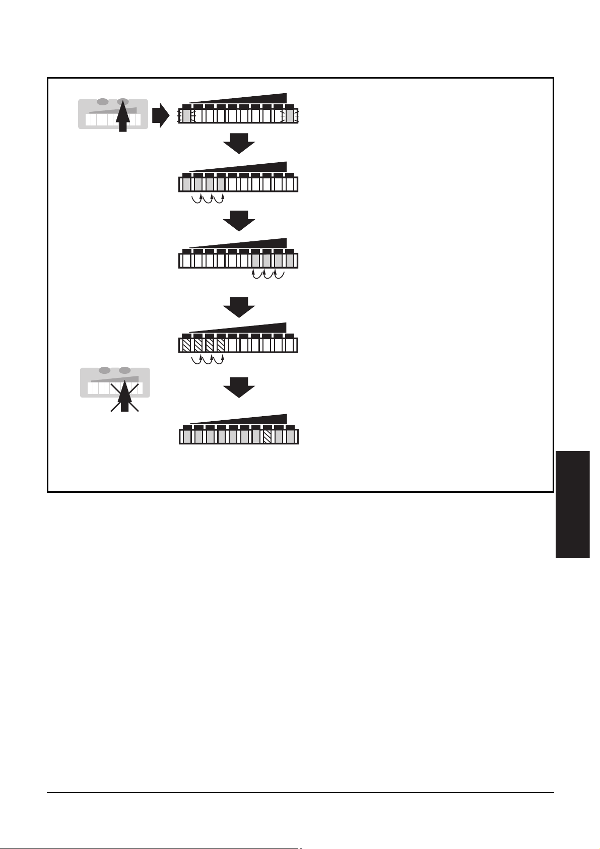
■■
Werkseinstellung wieder herstellen (Reset)
Drücken Sie die Taste Learn/Set
und halten Sie sie gedrückt.
Die grünen LEDs rechts und links
blinken,
nach 5s füllt sich der LED-Balken
(grün) von links nach rechts,
nach weiteren 5s füllt sich der
LED-Balken (grün) von rechts nach
links,
Die Anzeige verlischt kurzzeitig.
Alle Einstellungen werden auf
Werkseinstellung zurückgesetzt,
das Gerät geht in den Run-Modus
Strömung.
LO HI
LO HI
HILO
LO HI
nach weiteren 5s füllt sich der
LED-Balken (orange) von links
nach rechts
(lassen Sie die Taste los, sobald
die ersten LEDs orange leuchten).
LO HI
>15...<20s
M
S
M
S
Page 18
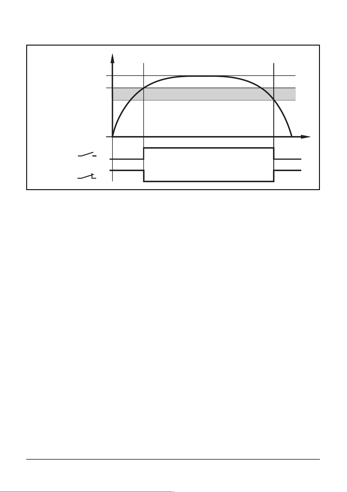
Hysteresefunktion
Steigt die Strömungsgeschwindigkeit, schaltet der Ausgang bei
Erreichen des Schaltpunkts (SP).
Sinkt die Strömungsgeschwindigkeit wieder, schaltet der Ausgang
zurück, wenn der Wert “SP minus Hysterese” erreicht ist.
Die Hysterese wird wesentlich beeinflußt von der Wahl des
Arbeitsbereichs auf der Empfindlichkeitskurve des Sensors:
• Bei Abgleich auf HI-Flow-Werte im Bereich 0 ... 60cm/s beträgt die
Hysterese 2 - 4cm/s (Werte gelten für Wasser).
• Bei Abgleich auf HI-Flow-Werte oberhalb 100cm/s vergrößert sich
die Hysterese mit steigender Strömungsgeschwindigkeit.
Die typische Ansprechzeit des Geräts beträgt 3 ... 8s. Sie kann durch
Einstellung des LO-Teach und des Schaltpunkts beeinflußt werden:
• Je niedriger LO-Teach oder Schaltpunkt eingestellt werden desto
schneller schaltet das Gerät ein.
• Je höher LO-Teach oder Schaltpunkt eingestellt werden desto
schneller schaltet das Gerät aus.
18
OUT
t
1
0
1
0
OUT
Maximalströmung
Strömung
Schaltpunkt (SP)
Minimalströmung
Hysterese
Page 19
20
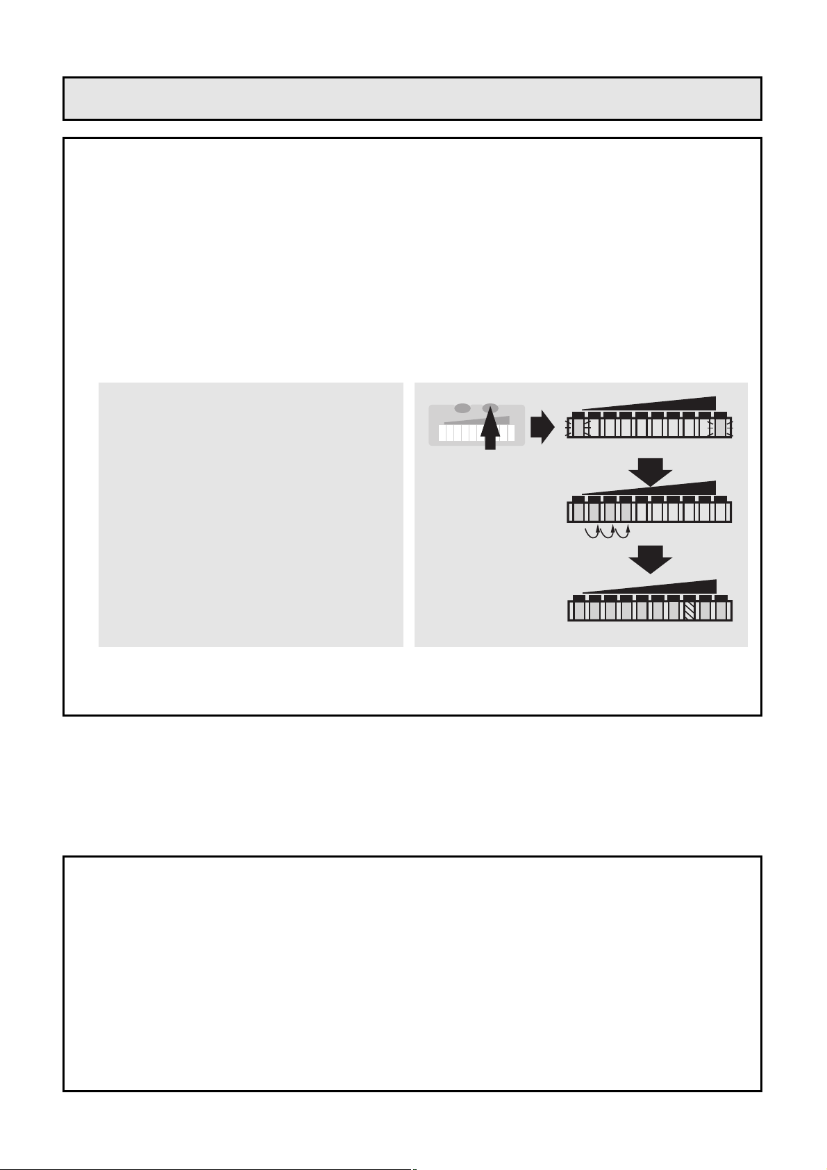
Further setting options (→ page 27)
• The HI-Teach is sufficient for the majority of waterbased applicati-
ons. Optional: adjustment to minimum flow (LO-Teach).
• Setting of the switch point (for changing the reaction time and
excess gain).
• Setting for monitoring and optical indication of excess flow.
• Activate / deactivate the function for remote adjustment.
• Reset to factory settings.
• Installation
Mounting → page 24, electrical connection → page 26.
• HI-Teach
Apply the operating voltage.
After approx. 15s the unit is ready.
Allow the medium to flow through the system at the required
maximmum flow rate (HI).
• The unit is ready for normal operation.
Press the Learn/Set button and
keep it pressed.
The green LEDs on the right and
on the left flash,
after 5s the LED bar (green) fills
from left to right
(release the button as soon as
the first LEDs light).
The indication goes off briefly.
The unit stores the current flow
as maximum flow.
LO HI
LO HI
HILO
>5...<10
M
S
Brief adjustment instructions
Page 20
ENGLISH
21
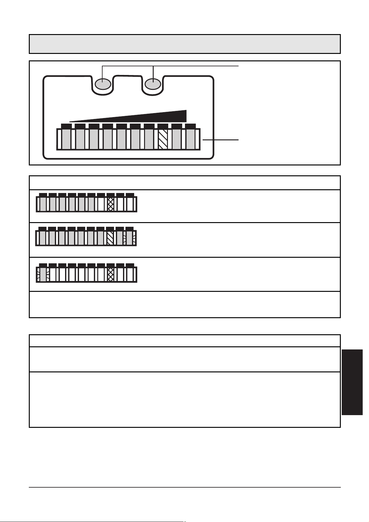
MODE /
ENTER
2468
LEARN /
SET
103579
LO HI
FLOW RATE
setting buttons
current flow within the display range
(LED bar green)
Indication of the switch point (SP):
LED orange: flow ≥ SP; LED red: flow < SP
Function display (Run mode)
excess flow (LED 9 flashes)
underflow (LED 0 flashes)
function display
2468103579
2468103579
Controls and visual indication
Mode / Enter:
• selection of the menu items and acknowledgement
Learn/Set:
• adjustment to maximum / minimum flow;
• reset to factory settings
• setting of values
(scrolling by holding pressed;incremental by pressing briefly)
Setting buttons
Page 21
22
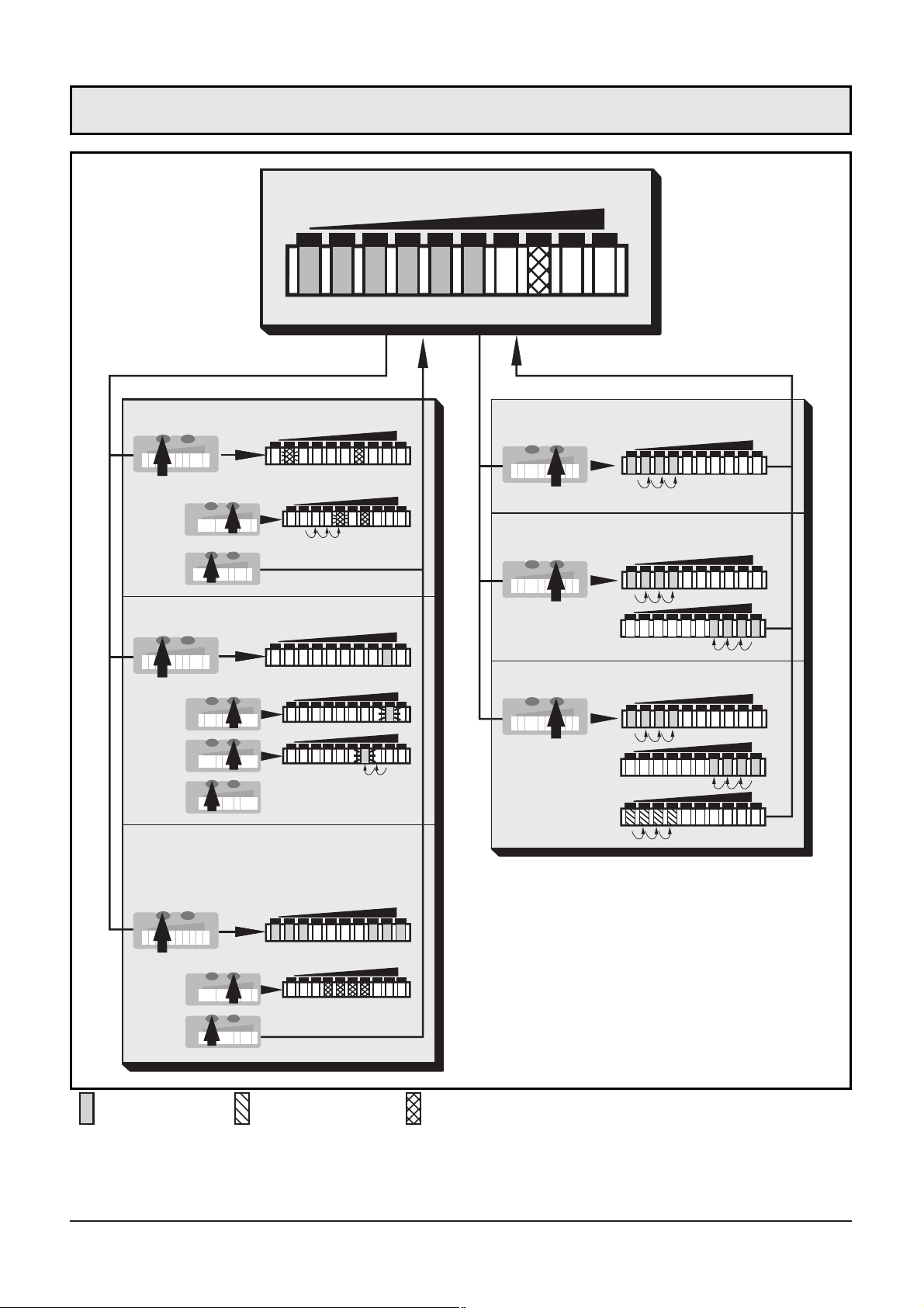
2468103579
LO
HI
1x
>5s
1x
2x
5s
1x
...
3x
> 5s
1x
>5...<10s
>10...<15s
>15...<20s
Adjustment to minimum flow
Adjustment to maximum flow
Unit functions
(ENTER button)
Adjustment /
factory setting
(SET button)
Monitoring excess flow
Setting the switch point
Activate / deactivate the
function for remote
adjustment
Run mode
LED = green LED = orange LED = red
Menu structure
Factory reset
Page 22
The flow monitor
• detects the flow velocity in liquid and gaseous media
• switches the output according to the programming
(N.O./ or N.C./ , programmmable by wiring; → page 26)
• and indicates the relative flow value within the adjustable detection
range by means of LEDs:
- LED 0 = lower limit of the detection range (maximum value / LO)
- LED 9 = upper limit of the detection range (minimum value / HI)
• It is also possible to indicate:
- Switching status (LED red: flow below the switch point,
LED orange: flow has reached the switch point).
- Excess flow: LED 9 flashes if the flow is considerably higher
(2 LEDs) than the display range.
- Underflow / flow standstill: LED 0 flashes if the flow is lower than
the display range.
ENGLISH
23
Contents
Function and features . . . . . . . . . . . . . . . . . . . . . . . . . . . page 23
Installation . . . . . . . . . . . . . . . . . . . . . . . . . . . . . . . . . . . page 24
Electrical connection . . . . . . . . . . . . . . . . . . . . . . . . . . . . page 26
Programming . . . . . . . . . . . . . . . . . . . . . . . . . . . . . . . . . page 27
Installation and set-up / Operation / Maintenance . . . . . . . page 29
Technical data . . . . . . . . . . . . . . . . . . . . . . . . . . . . . . . . . page 29
Programming diagrams / Technical information . . . . . . . . . page 30
Function and features
Page 23
The unit is adaptable for various process fittings (adapters to be
ordered separately as accessories).
• In the case of horizontal pipes mount the unit from the side, if possible (fig. 1).
When the unit is to be mounted at the bottom of the pipe, it should
be free from deposits.
When the unit is to be mounted at the top of the pipe, it should be
completely filled with the medium to be monitored.
• In the case of vertical pipes mount the unit in a place where the
medium flows upwards (fig. 2).
To avoid malfunction a minimum
distance between the flow monitor and bends, valves, changes
in cross-section or such like must
be observed:
• Min. 5 x pipe diameter
upstream (A),
• min. 3 x pipe diameter downstream (B).
24
Installation
D
A
B
min.
5 x D
min.
3 x D
1 2
3
Page 24
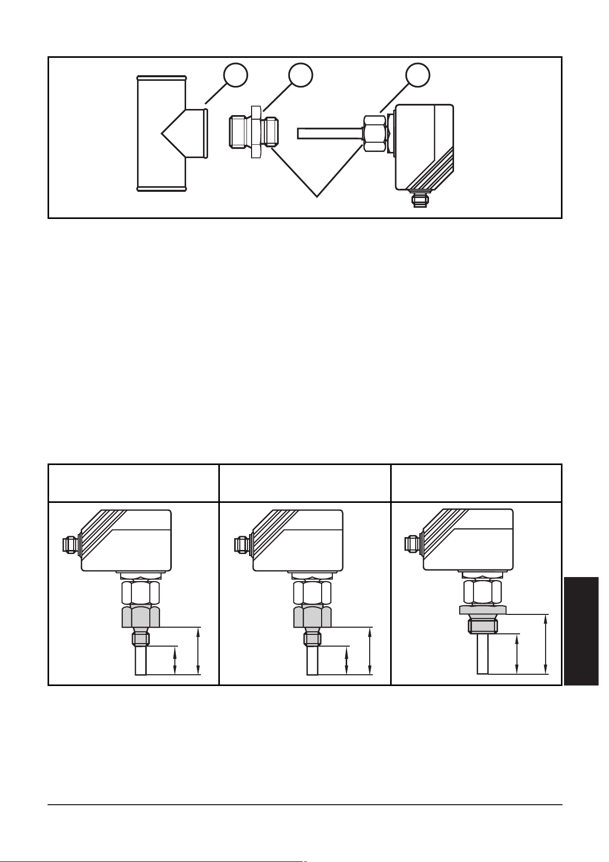
1. Lubricate the nut (3) and all threads with grease to ensure the nut
can be loosened and tightened several times.
Note: No grease must be applied to the sensor tip (A).
2. Screw the suitable adapter (2) onto the process fitting (1).
3. Insert the flow monitor into the adapter. While keeping the unit
aligned tighten the nut (3); (max. tightening torque 50Nm).
Insertion depth of the sensor: min. 12mm in the pipe. When the
adapters are used which are available as accessories, the correct depth
is ensured.
Note: The sensor tip must not touch the pipe wall.
ENGLISH
25
1 2 3
⎩
⎨
⎧
A
thread M18 x 1.5
27
13,52713,5
35
21
mounting dimension
with M12 adapter
mounting dimension
with G¼ adapter
mounting dimension
with G½ adapter
Page 25
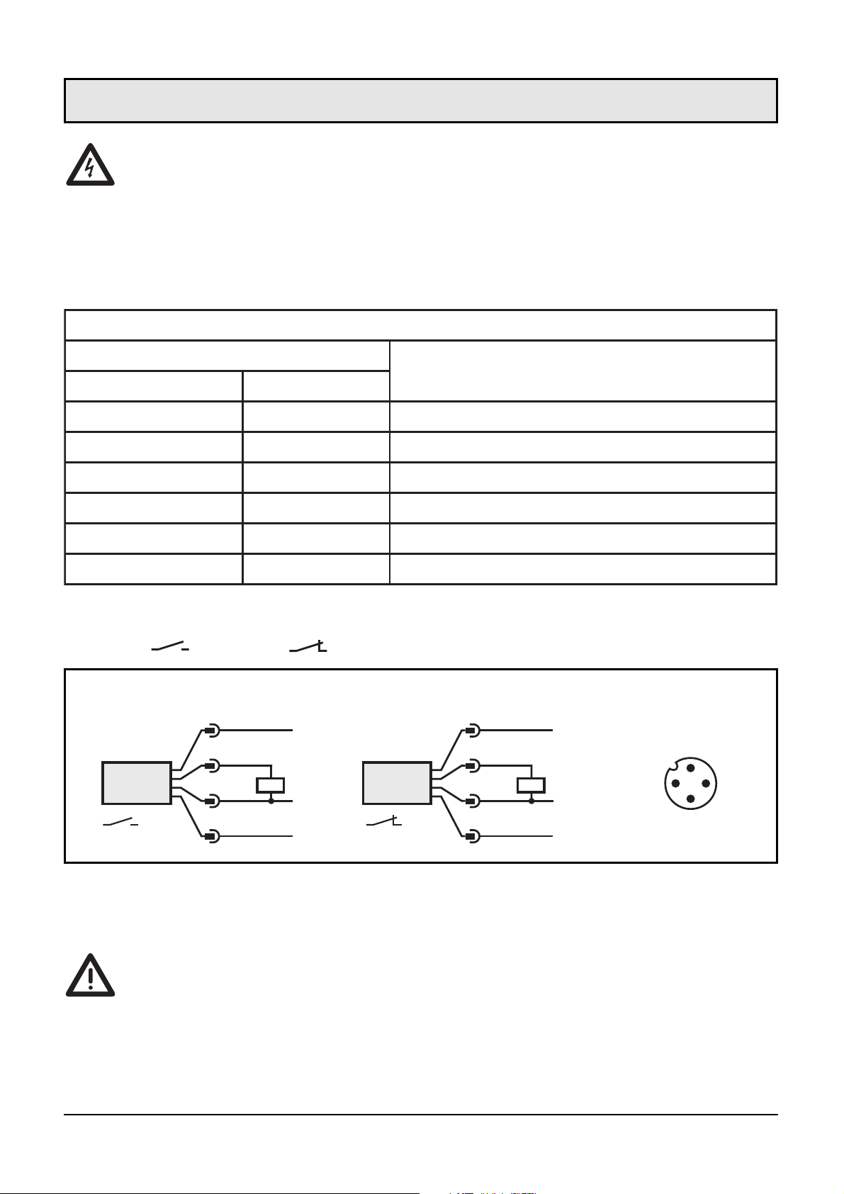
The unit must only be connected by an electrician.
The national and international regulations for the installation of
electrical equipment must be observed.
Voltage supply to EN50178, SELV, PELV.
The device shall be supplied from an isolating transformer having a secondary Listed fuse rated as noted in the following table.
Disconnect power before connecting the unit.
Wiring ( = N.O. / = N.C.):
If the function for remote adjustment is active:
Use 4-wire connection cables without a link between pins 2 and 4.
With 3-wire sockets with a link between pin 2 and pin 4 switching of
the output stage triggers the remote adjustment!
Failure indication: In the case of a short circuit the function indication
and the red LED row are lit alternately.
26
Electrical connection
P
L
+
2
1
4
3
L-
P
L
+
2
3
4
1
L-
3
1
4
2
WH
BU
BK
BN
WH
BN
BK
BU
connector
view (sensor)
P = programming wire (for remote adjustment)
Core colours of ifm sockets:
1 = BN (brown), 2 = WH (white), 3 = BU (blue), 4 = BK (black)
Overcurrent protection
Control-circuit wire size
Maximum protective device rating
Ampere
AWG (mm
2
)
26 (0.13) 1
24 (0.20) 2
22 (0.32) 3
20 (0.52) 5
18 (0.82) 7
16 (1.3 ) 10
Page 26
■■
Setting of the detection range
HI-Teach
• Allow the medium to flow through the system at the required maximum flow rate.
• Press the Learn/Set button for >5...<10s (= adjustment to maximum flow / upper limit of the detection range).
Optional: LO-Teach
The HI-Teach is sufficient for the majority of waterbased applications. Optional: adjustment to minimum flow.
• Allow the medium to flow through the system at the required minimum flow rate or bring flow to a standstill.
• Press the Learn/Set button for
>10...<15s
(= adjustment to mini-
mum flow or flow standstill / lower limit of the detection range).
■■
Remote adjustment via programming wire
Apply the operating voltage (+U
B
) to pin 2 for the respective time.
■■
Setting of the switch point
• Press the Mode/Enter button briefly.
• Press the Learn/Set button for 5s,
• keep the Learn/Set button pressed or press the button several times
until the requested switch point is set.
• Press the Mode/Enter button briefly.
■■
Monitoring excess flow
• Press the Mode/Enter button twice.
• Press the Learn/Set button for 5s, release the button when LED
flashes.
• Press the Learn/Set button several times to shift the LED for the
maximum display value.
• Press the Mode/Enter button briefly.
ENGLISH
27
Programming
Page 27

■■
Activate / deactivate the function for remote adjustment
• Press the Mode/Enter button three times.
• Press the Learn/Set button for 5s,
• keep the Learn/Set button pressed or press the button several times
until the requested function is set (function active, when 3 LEDs
on the right and 3 LEDs left are lit green; function not active,
when the 4 LEDs in the middle are lit in red).
• Press the Mode/Enter button briefly.
■■
Reset to factory settings
• Press the Learn/Set button for
>15...<20s.
■■
The following applies to all setting procedures:
• If no button is pressed for 15s during the setting procedure, the
unit returns to the operating mode with the parameter values
unchanged.
• If adjustment has not been possible, all the red LEDs flash. The unit
returns to the operating mode with the parameter values
unchanged.
■■
Locking / Unlocking
The unit can be electronically locked to prevent unwanted adjustment
of the set parameters: Press both setting buttons for 10s (the unit
must be in Run mode). Indication goes out briefly (acknowledgement
of locking / unlocking).
Units are delivered from the factory in the unlocked state.
If the unit is locked, it is possible to indicate
• the current switch point (press the Mode/Enter button once),
• the setting of the function “monitoring excess flow” (press the
Mode/Enter button two times),
• the setting of the function for remote adjustment (press the
Mode/Enter button three times).
28
Page 28
After mounting, wiring and setting check whether the unit operates
correctly. At power on, all LEDs light and go off one after the other.*
The unit is then ready for operation.
*During this time the output is switched according to the programming: ON
with the NO function and OFF with the NC function.
Failure indication: In the case of a short circuit the function indication and the red LED row are lit alternately.
Recommended maintenance
Check the sensor tip for build-up from time to time. Clean it with a
soft cloth. If necessary, build-up which adheres firmly (e.g. lime) can
be removed with a common vinegar cleansing agent.
Technical data
ENGLISH
29
Installation and set-up / Operation / Maintenance
Operating voltage [V] . . . . . . . . . . . . . . . . . . . . . . . . . . . . . . 20 ... 36 DC
1)
Current rating [mA]. . . . . . . . . . . . . . . . . . . . . 400; short-circuit protection;
reverse polarity protection / overload protection
Voltage drop [V] . . . . . . . . . . . . . . . . . . . . . . . . . . . . . . . . . . . . . . . . < 2.5
Current consumption [mA] . . . . . . . . . . . . . . . . . . . . . . . . . . . . . . . . < 80
Liquids
Medium temperature [°C] . . . . . . . . . . . . . . . . . . . . . . . . . . . . . -25 ... +80
Setting range [cm/s] . . . . . . . . . . . . . . . . . . . . . . . . . . . . . . . . . . . 3 ... 300
Greatest sensitivity [cm/s] . . . . . . . . . . . . . . . . . . . . . . . . . . . . . . . . 3 ... 60
Max. temperature gradient of medium [K/min] . . . . . . . . . . . . . . . . . . . 300
Gases
Medium temperature [°C] . . . . . . . . . . . . . . . . . . . . . . . . . . . . . -25 ... +80
Setting range [cm/s] . . . . . . . . . . . . . . . . . . . . . . . . . . . . . . . . 200 ... 3000
Greatest sensitivity [cm/s] . . . . . . . . . . . . . . . . . . . . . . . . . . . . . 200 ... 800
Response time [s] . . . . . . . . . . . . . . . . . . . . . . . . . . . . . . . . . . . . . . 1 ... 10
Power-on delay time [s] . . . . . . . . . . . . . . . . . . . . . . . 15, optically indicated
Pressure rating [bar]. . . . . . . . . . . . . . . . . . . . . . . . . . . . . . . . . . . . . . . 300
Operating temperature [°C] . . . . . . . . . . . . . . . . . . . . . . . . . . . . -25 ... +80
Protection . . . . . . . . . . . . . . . . . . . . . . . . . . . . . . IP 67 (IEC60529) / UL50)
Shock resistance [g]. . . . . . . . . . . . . . . . . . . . 50 (DIN / IEC 68-2-27, 11 ms)
Vibration resistance [g] . . . . . . . . . . . . . . 20 (DIN / IEC 68-2-6, 55-2000 Hz)
Housing material . . . . . . . . . . . . . . . . . . . . . . . . . . . . . . . . . . . . PBT-GF 20
Sensor material (SI10xx) . . . . . . . . . . . . . . . . . . . . . stainless steel (316S12);
O-ring: FPM 8x1.5 gr 80° Shore A
Sensor material (SI11xx) titanium; O-ring: FPM 8x1.5 gr 80° Shore A
1)
to EN50178, SELV, PELV
Page 29
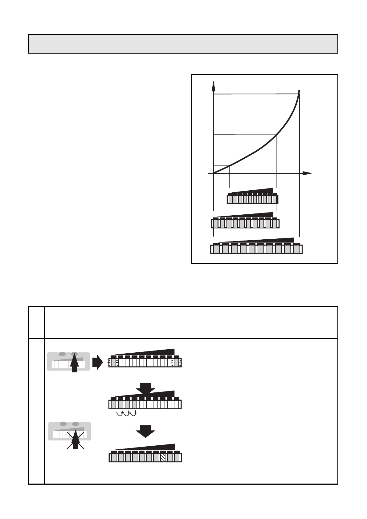
■■
Setting of the detection range
The detection range (window)
is determined by:
• Adjustment to the required
maximum flow (HI-Teach)
= upper limit of the window.
This setting is sufficient for the
majority of waterbased applications.
• Additionaly: adjustment to the
required minimum flow / flow
standstill (LO-Teach) = lower
limit of the window (optional).
• Adjustment to maximum
flow (HI-Teach)
The unit detects the current flow and sets this value as the maximum
value for the LED display (LED 9).
30
1
2
Press the Learn/Set button and
keep it pressed.
The green LEDs on the right and
on the left flash,
after 5s the LED bar (green) fills
from left to right
(release the button as soon as the
first LEDs light).
The indication goes off briefly.
The unit stores the current flow
as maximum flow and passes into
the operating mode.
LO HI
LO HI
HILO
>5...<10s
M
S
Apply the operating voltage. After approx. 15s the unit is ready.
Allow the medium to flow through the system at the required
maximum flow rate.
2468103579
LO HI
2468103579
LO HI
2468103579
LO HI
0
flow velocity
sensor
signal
Programming diagrams / Technical information
M
S
Page 30
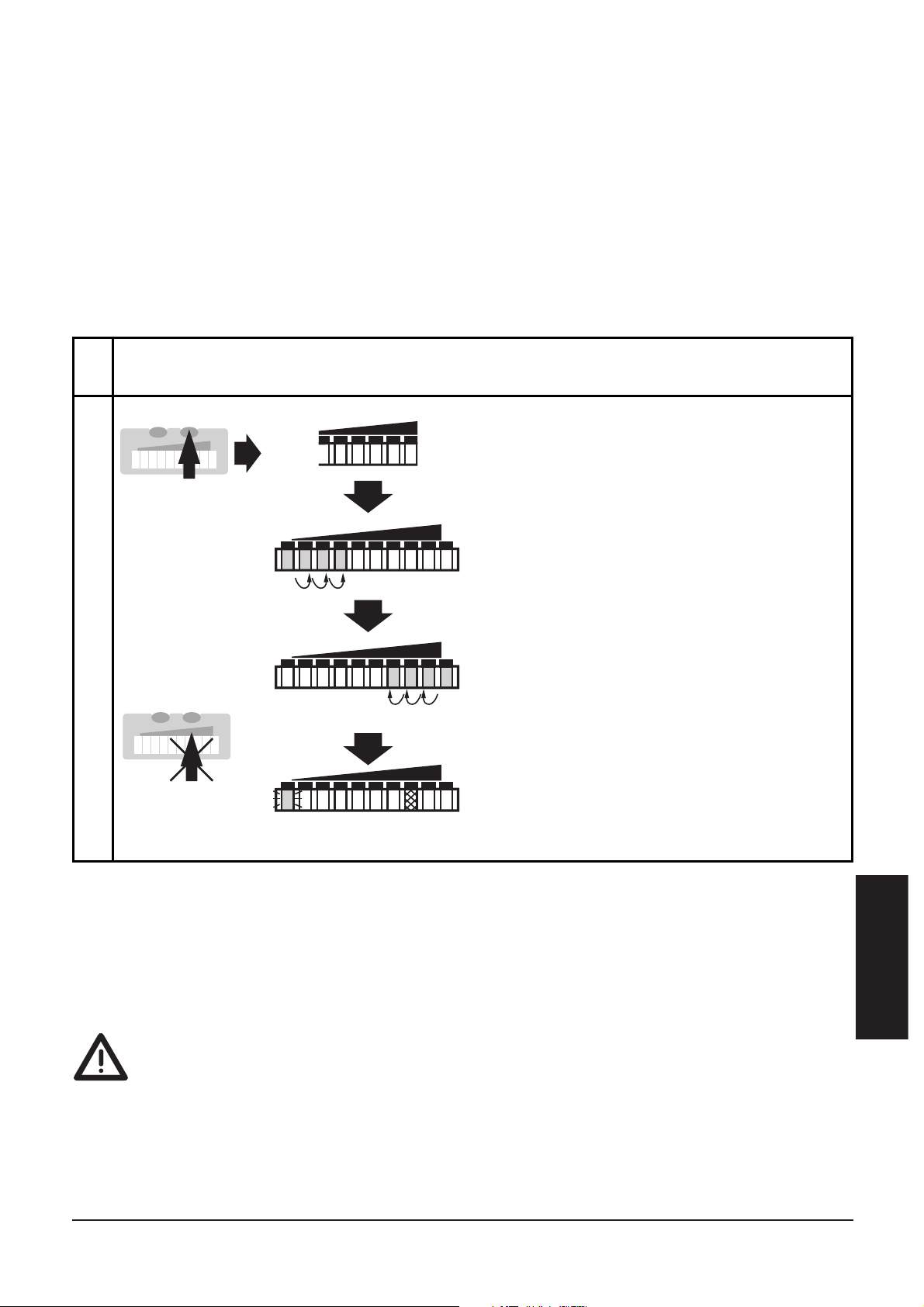
• Adjustment to minimum flow / flow standstill (LO-Teach),
optional
The unit detects the current flow and sets this value as the minimum
display value for the LED display. In normal operation the first green
LED (LED 0) flashes when the flow falls below this value (or when it
comes to a standstill).
NOTE: The LO-Teach operation may only be carried out after the HITeach operation.
• Remote adjustment
You can also adjust the unit via the programming wire, if the function
for remote adjustment is active. Apply the operating voltage (+U
B
) to
pin 2 (P) for the respective time:
>5...<10s
for HI-Teach;
>10...<15s
for
LO-Teach
ENGLISH
31
If the operating voltage is applied to pin 2 for more than 15s,
• all adjustments are set back to factory setting.
If the operating voltage is applied to pin 2 for more than 20s,
• the adjustment does not become effective; the unit passes into the
operating mode with unchanged values,
• the unit is locked (the buttons are inactive as long as the operating
voltage is applied to pin 2).
1
2
Press the Learn/Set button and
keep it pressed.
The green LEDs on the right and
on the left flash,
after 5s the LED bar (green) fills
from left to right
after a further 5s the LED bar
(gren) fills from right to left
(release the button as soon as the
first LEDs on the right light).
The indication goes off briefly.
The unit stores the current flow
as minimum flow and passes into
the operating mode.
LO HI
HILO
LO HI
>10...<15s
M
S
Allow the medium to flow through the system at the required
minimum flow rate or bring to a standstill.
M
S
Page 31
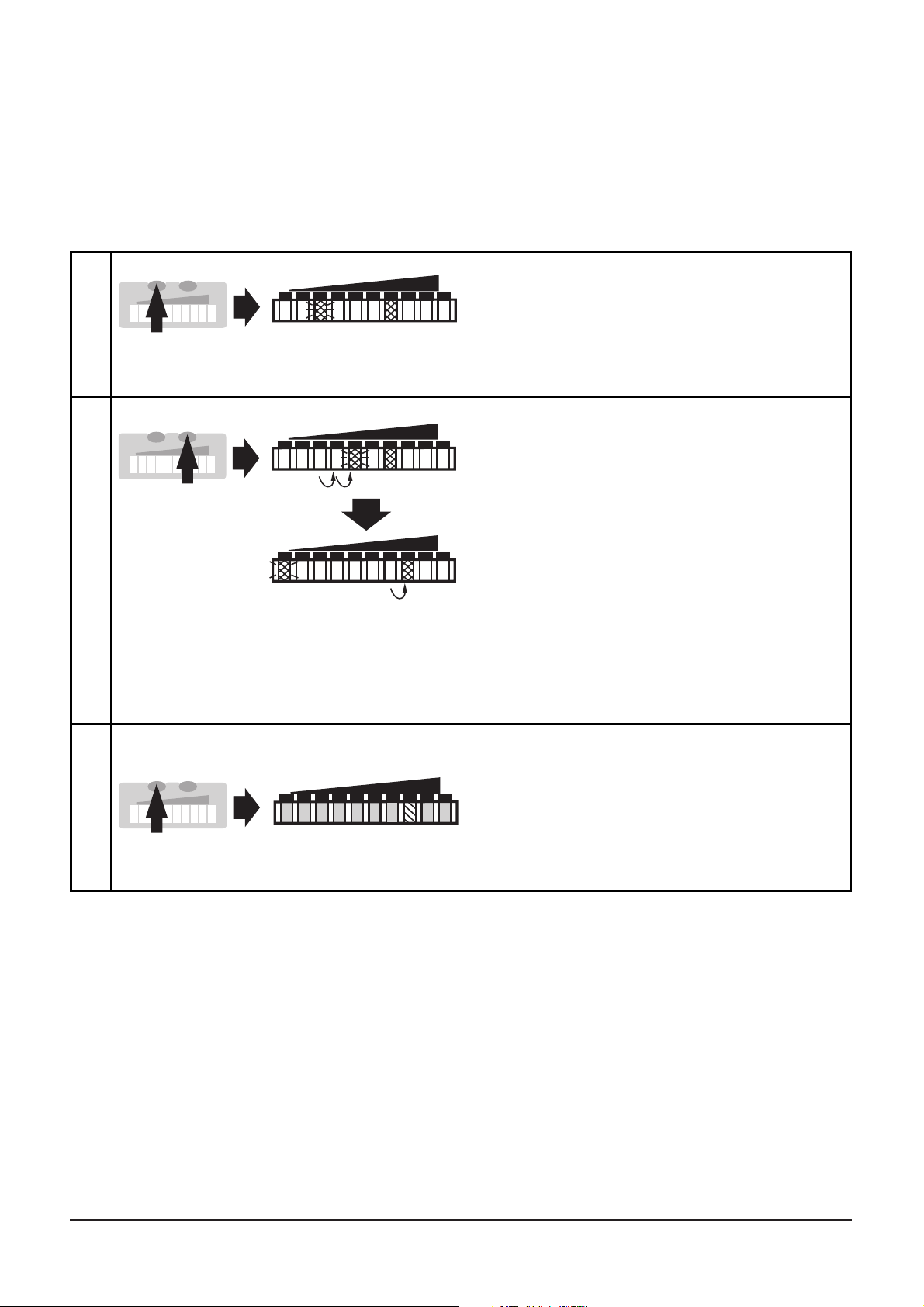
■■
Setting of the switch point
The switch point is preset at the factory (LED 7). The setting influences the reaction time of the unit.
• High switch point = fast reaction in the case of flow decrease.
• Low switch point = fast reaction in the case of flow increase.
32
*Decrease the switch point: Let the flashing and lit LEDs move to the
maximum setting value. Then the cycle starts again at the minimum setting
value.
**Overflow: If the flashing LED and the lit LED exceed the maximum setting
value, the cycle starts again at the minimum setting value.
1
2
Press the Mode/Enter button
briefly. The current switch point is
indicated:
LED lit: coarse setting, LED
flashes: fine setting.
Press the Learn/Set button and
keep it pressed.
After 5s the switch point is
increased* (incremental by
pressing briefly or scrolling by
holding pressed).
Indication:
The flashing LED moves from left
to right. After LED 9 has been
reached the cycle starts again at
LED 0. The LED which is constantly
lit moves on by one position.**
LO HI
LO HI
LO HI
1 x
M
S
M
S
3
Press the Mode/Enter button
briefly (acknowledgement).
The indication goes off briefly.
The set switch point becomes
effective; the unit passes into the
operating mode.
HILO
M
S
>5s
Page 32
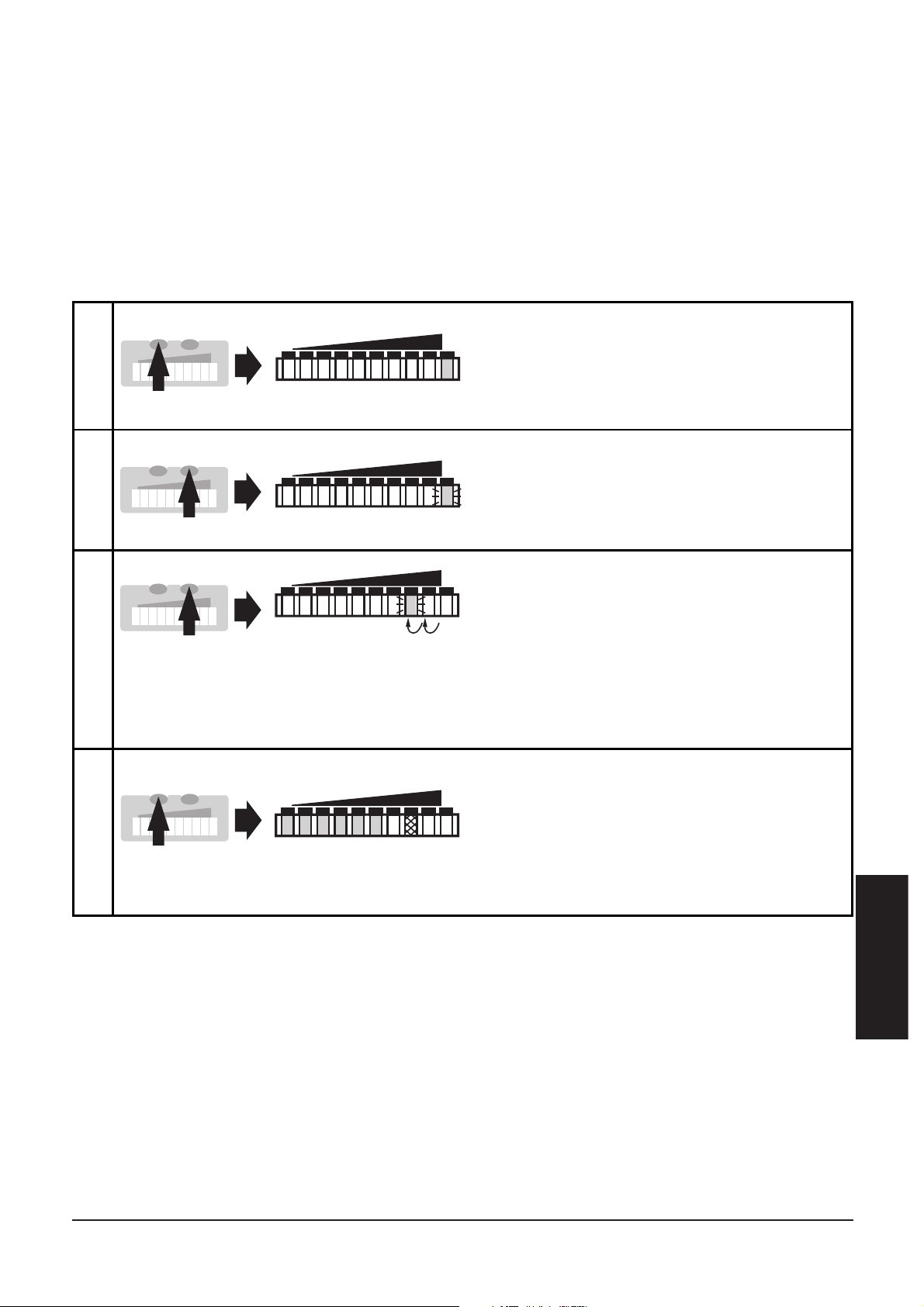
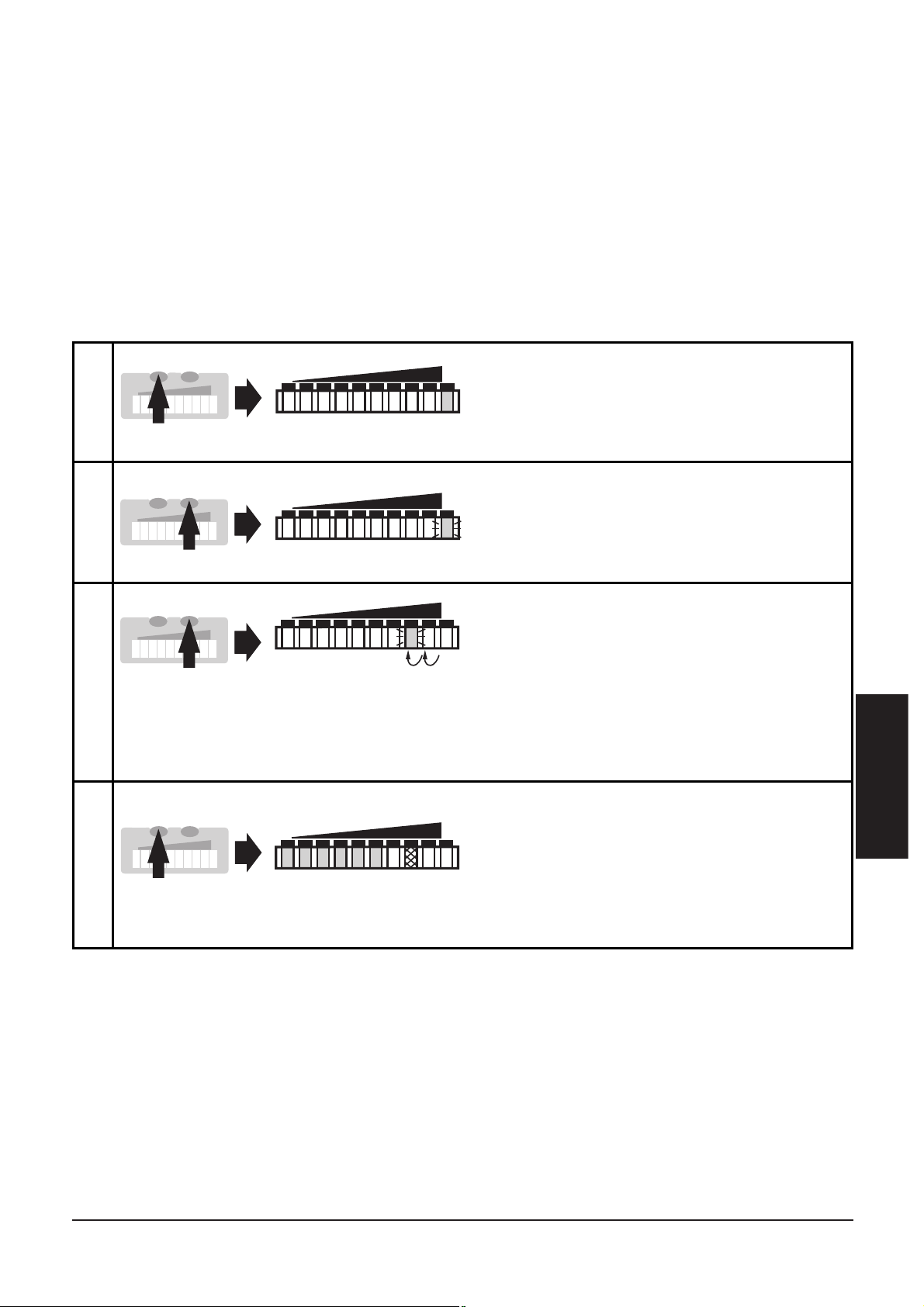
■■
Monitoring excess flow
With this function the position of the display window within the
detection range can be defined: Shift the LED for the maximum display value to position 8, 7, 6 or 5. In the case of maximum flow all
LEDs from 0 up to this LED are lit. The LEDs above the range signal
excess flow. If the switch point is above this range, the unit switches
in the case of excess flow.
Please note:
The display value is reset (to LED 9) after each maximum flow rate adjustment
(HI-Teach.
ENGLISH
33
1
2
Press the Mode/Enter button
twice. The current setting is indicated (green LED).
Press the Learn/Set button for 5s
(until LED flashes).
LO HI
LO HI
2 x
M
S
M
S
3
Press the Learn/Set button
several times until the requested
LED flashes (LED 8, 7, 6 or 5).
Each time the button is pressed
the LED moves back by one position.
When it is lower than LED 5 the
cycle starts again at LED 9.
LO HI
M
S
4
Press the Mode/Enter button
briefly (acknowledgement).
The indication goes off briefly.
The unit stores the new setting
and passes into the run mode.
HI
LO
M
S
5s
Page 33
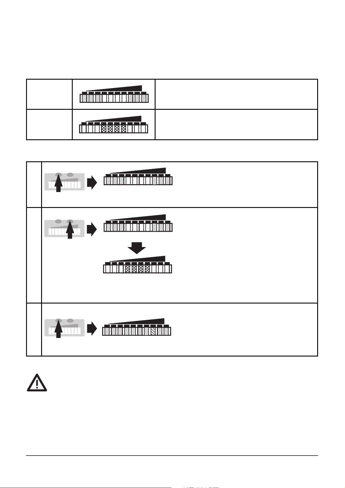
■■
Activate / deactivate the function for remote adjustment
If the function is active, the unit can be adjusted by applying voltage
to pin 2.
Unit supplied: function active.
If the function for remote adjustment is active and the operating
voltage is applied to pin 2 for more than 20s, the unit is locked (the buttons are inactive as long as the operating voltage is applied to pin 2).
Use 4-wire connection cables without a link between pins 2 and 4.
With 3-wire sockets with a link between pin 2 and pin 4 switching of
the output stage triggers the remote adjustment!
34
Function
active
The 3 LEDs on the right and left are lit in
green.*
HILO
Function
not active
The 4 LEDs in the middle are lit in red.*
LO HI
1
2
Press the Mode/Enter button three
times.
The current setting is indicated.
Press the Learn/Set button and
keep it pressed,
after 5s the function changes.
(Each time the Learn/Set button
is pressed the function changes
again).
HILO
HILO
LO HI
3 x
M
S
>5s
M
S
3
Press the Mode/Enter button
briefly (= acknowledgement).
The indication goes off briefly,
the unit then passes into the
operating mode.
HILO
M
S
*The LEDs flash if voltage is applied to pin 2.
Page 34
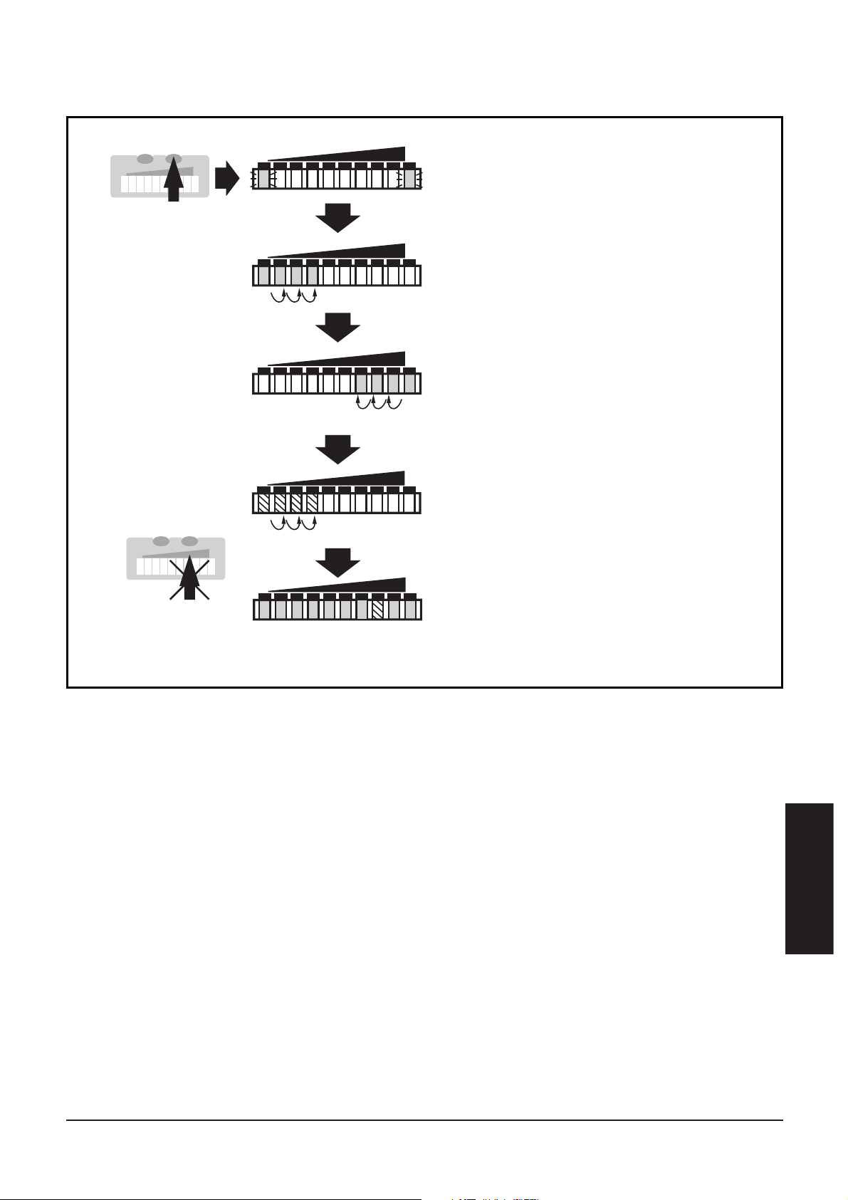
■■
Return to factory setting
ENGLISH
35
Press the Learn/Set button and
keep it pressed.
The green LEDs on the right and
on the left flash,
after 5s the LED bar (green) fills
from left to right,
after a further 5s the LED bar
(green) fills from right to left,
The indication goes off briefly.
All settings are returned to factory
setting and the unit passes into
the run mode flow.
LO HI
LO HI
HILO
LO HI
after a further 5s the LED bar
(orange) fills from left to right
(release the button as soon as the
first orange LEDs light).
LO HI
>15...<20s
M
S
M
S
Page 35
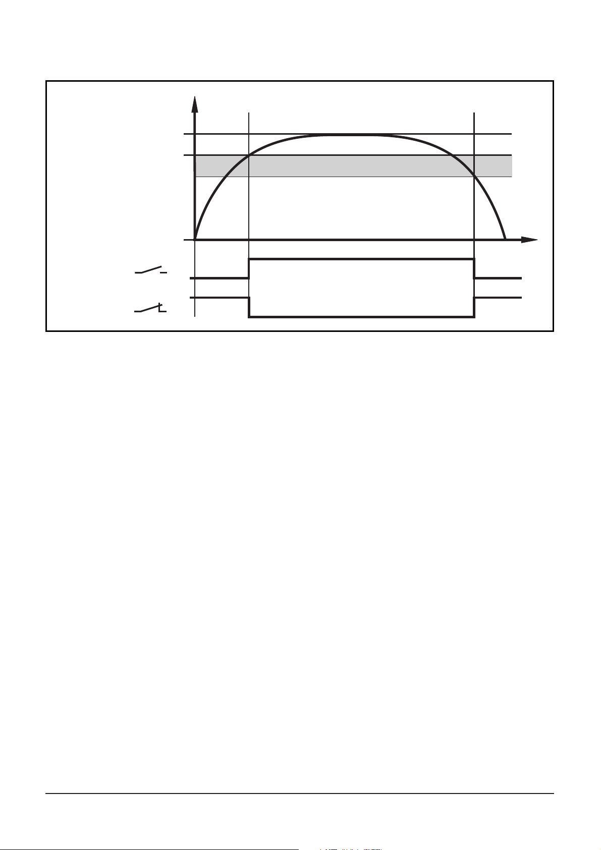
Hysteresis function
When the flow rises, the output switches when the switch point (SP)
has been reached.
When the flow falls again, the output switches back when the value
"SP minus hysteresis" has been reached.
The hysteresis is considerably influenced by the choice of the operating range on the sensitivity curve of the sensor:
• In the case of adjustment to HI-Flow values in the range 0 ... 60 cm/s
the hysteresis is 2 - 4cm/s (values apply to water).
• In the case of adjustment to HI-Flow values above 100cm/s the
hysteresis increases as the flow rises.
The typical response time of the unit is 3 ... 8 s. It can be influenced
by setting the LO-Teach and the switch point:
• The lower the LO-Teach or the switch point is set, the faster the unit
switches on.
• The higher the LO-Teach or switch point is set, the faster the unit
switches off.
36
OUT
t
1
0
1
0
OUT
maximum flow
flow
switch point (SP)
minimum flow
hysteresis
Page 36
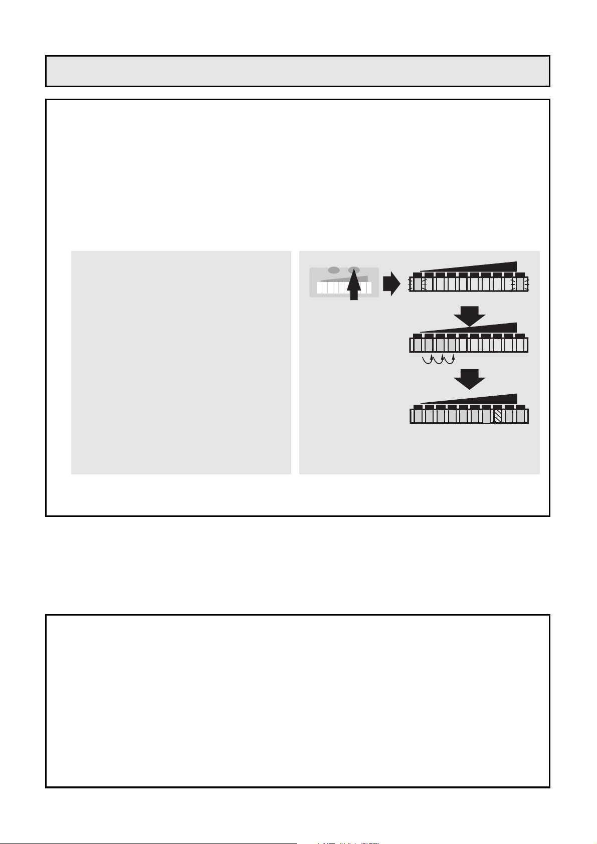
38
D’autres possibilités de réglage (→ page 45)
• Ce réglage (HI-Teach) suffit pour la plupart des applications à
base d'eau. Option: réglage sur débit minimum. (LO-Teach).
• Régler le seuil de commutation (pour changer le temps de
réponse et la capacité de réserve).
• Réglage pour surveillance et visualisation d'un débit excessif.
• Activer / désactiver la fonction "réglage à distance".
• Récupérer les réglages de base effectués en usine.
• Installation
Montage → page 42, raccordement électrique → page 44.
• HI-Teach
Mettre l’appareil sous tension
L'appareil est opérationnel après env. 15s.
Le débit du fluide doit être à la valeur maximale (HI) souhaité.
• L'appareil est opérationnel.
Appuyer sur le bouton
Learn/Set et le maintenir
appuyé.
Les LED vertes à droite et à
gauche clignotent;
après 5s la rampe de LED
s'allume de gauche à droite
(relâcher le bouton dès que les
premières LED s'allument).
L'affichage s'éteint brièvement.
L'appareil mémorise le débit
existant en tant que débit
maximum.
LO HI
LO HI
HILO
>5...<10
M
S
Notice succincte de réglage
Page 37
FRANÇAIS
39
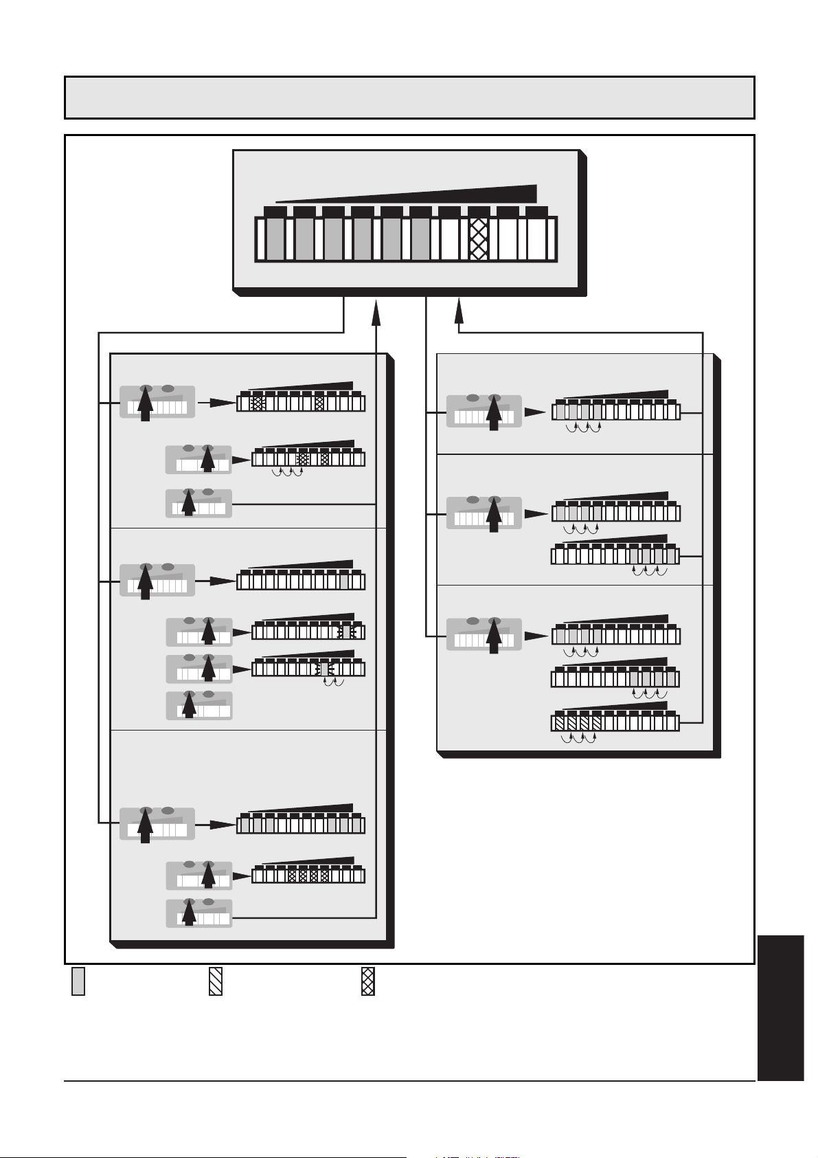
2468103579
LO
HI
1x
>5s
1x
2x
5s
1x
...
3x
> 5s
1x
>5...<10s
>10...<15s
>15...<20s
Réglage sur débit minimum
Réglage sur débit maximum
Fonctions
d’appareil
(Bouton ENTER)
Réglage
(Bouton SET)
Surveiller un débit excessif
Seuil de commutation
Activer / désactiver la
fonction réglage à distance
Mode Run
LED = verte LED = orange LED = rouge
Structure du menu
Réglages de base
Page 38
40
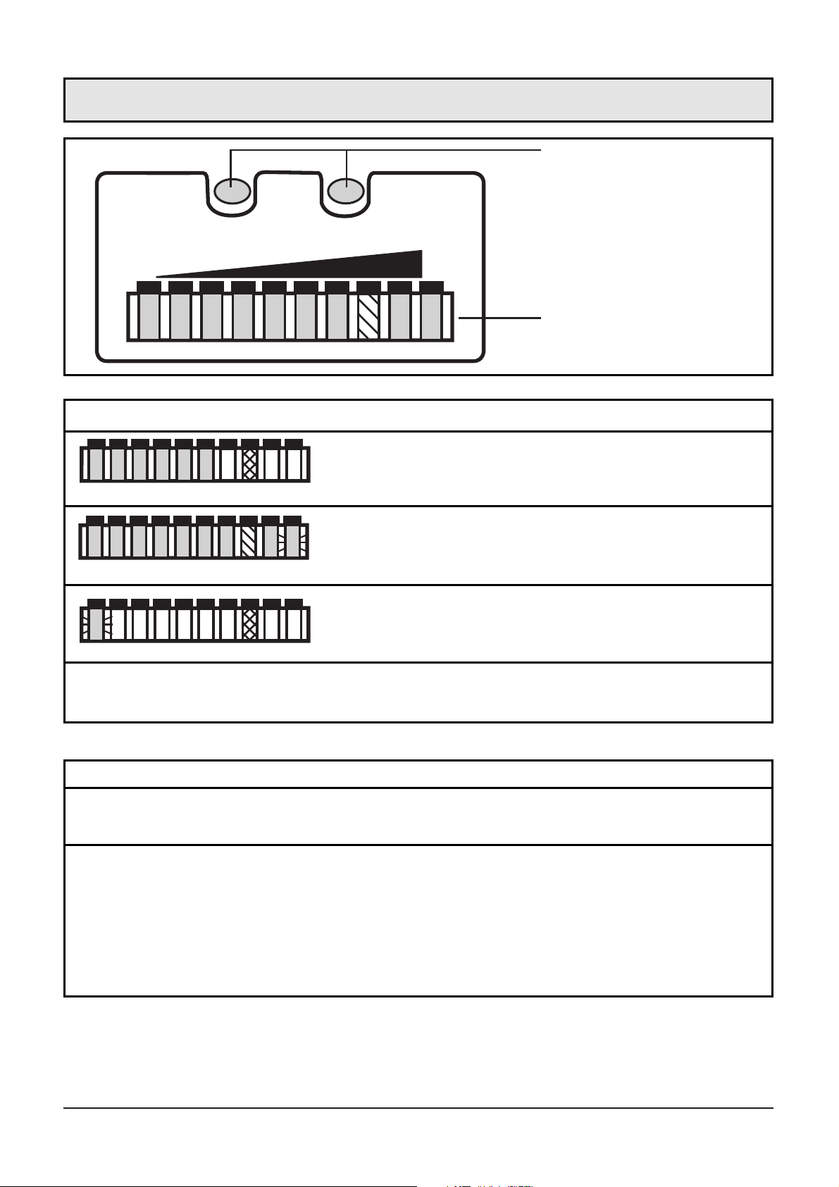
MODE /
ENTER
2468
LEARN /
SET
103579
LO HI
FLOW RATE
boutons-poussoir de
réglage
débit actuel du fluide dans la plage de
détection (rampe LED verte)
Indication du seuil de commutation (SP):
LED orange: débit ≥ SP; LED rouge: débit < SP
Indication de fonction (Mode RUN)
débit excessif (LED 9 clignote)
chute du débit (LED 0 clignote)
indication de
fonction
2468103579
2468103579
Eléments de service et d’indication
Mode/Enter:
• sélection des options de menu; validation
Learn/Set:
• réglage sur débit maximum / minimum /
• récupérer les réglages de base (Reset)
• réglage des valeurs
(en appuyant sur le bouton-poussoir et le maintenant appuyé,
pas à pas en appuyant sur le bouton-poussoir plusieurs fois)
Boutons-poussoir de réglage
Page 39
Le contrôleur de débit
• détecte la vitesse de circulation du fluide (milieux liquides et
gazeux),
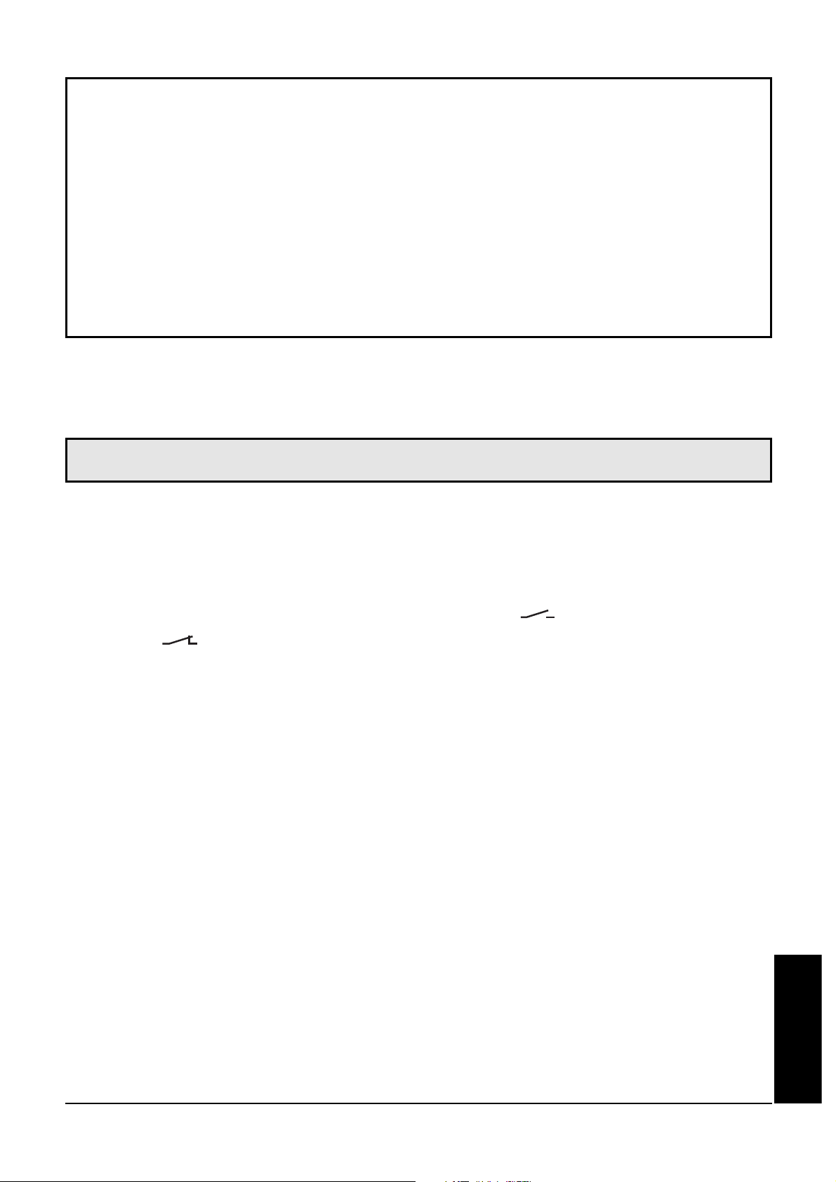
• commute la sortie en fonction de la programmation
(programmation normalement ouvert/ ou normalement
fermé/ , suivant le branchement de l'alimentation, → page 44),
• et indique un débit relatif dans la plage de détection réglable par
des LED:
- LED 0 = limite inférieure de la plage de détection (valeur minimale / LO)
- LED 9 = limite supérieure de la plage de détection (valeur maximale / HI)
• Il est également possible d'indiquer
- l'état de commutation de la sortie (LED rouge: débit inférieur au
seuil de commutation, LED orange: débit supérieur ou égal au
seuil de commutation),
- le dépassement de la limite supérieure de la plage de détection: la
LED 9 clignote lorsque le débit est nettement supérieur à l'échelle
de visualisation (2 LED),
- que le débit est inférieur au débit minimal ou nul: la LED 0
clignote lorsque le débit est inférieur à l'échelle de visualisation.
FRANÇAIS
41
Fonctionnement et caractéristiques
Contenu
Fonctionnement et caractéristiques . . . . . . . . . . . . . . . . . . page 41
Montage . . . . . . . . . . . . . . . . . . . . . . . . . . . . . . . . . . . . page 42
Raccordement électrique . . . . . . . . . . . . . . . . . . . . . . . . . page 44
Programmation . . . . . . . . . . . . . . . . . . . . . . . . . . . . . . . . page 45
Mise en service / Fonctionnement / Maintenance . . . . . . . . page 47
Données techniques . . . . . . . . . . . . . . . . . . . . . . . . . . . . page 47
Diagrammes de réglage / Informations techniques . . . . . . . page 48
Page 40
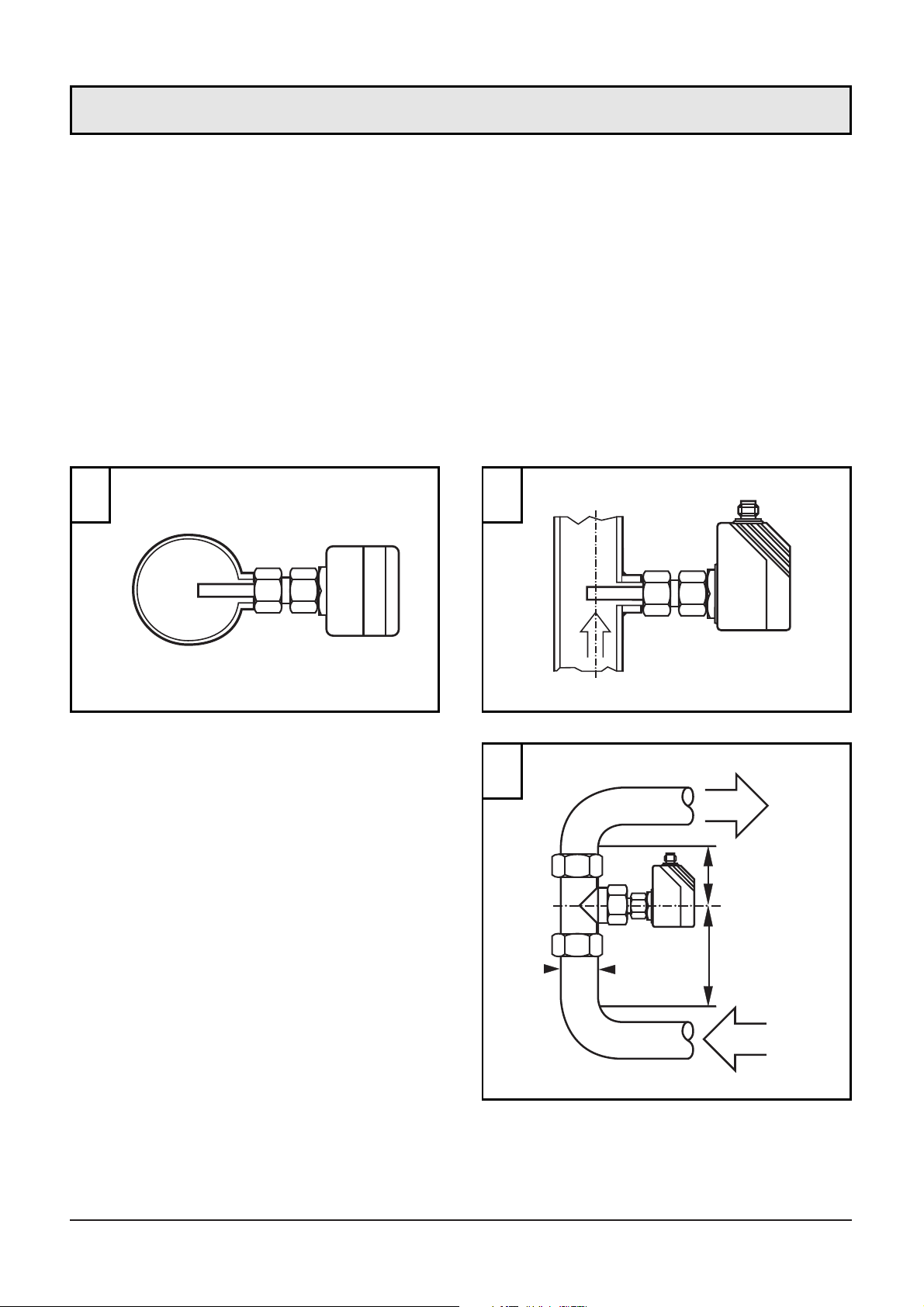
L'appareil est adaptable à différents types de raccords process (adaptateurs à commander séparément comme accessoires).
• Dans le cas des tubes horizontaux monter l'appareil latéralement, si
possible (fig. 1).
Lorsque l'appareil est monté par le bas le tube doit être dégagé de
dépôts.
Lorsque l'appareil est monté par le haut le tube doit être rempli
entièrement du fluide à surveiller.
• Dans le cas des tubes verticaux nous recommandons d’effectuer le
piquage là où le fluide monte (fig. 2).
Afin d’éviter un mauvais fonctionnement une distance minimum doit être respectée entre la
sonde et les coudes, vannes,
changements de section, etc.
• Min. 5 x diamètre de la canalisation en amont (A),
• min. 3 x diamètre de la canalisation en aval (B).
42
D
A
B
min.
5 x D
min.
3 x D
1 2
3
Montage
Page 41
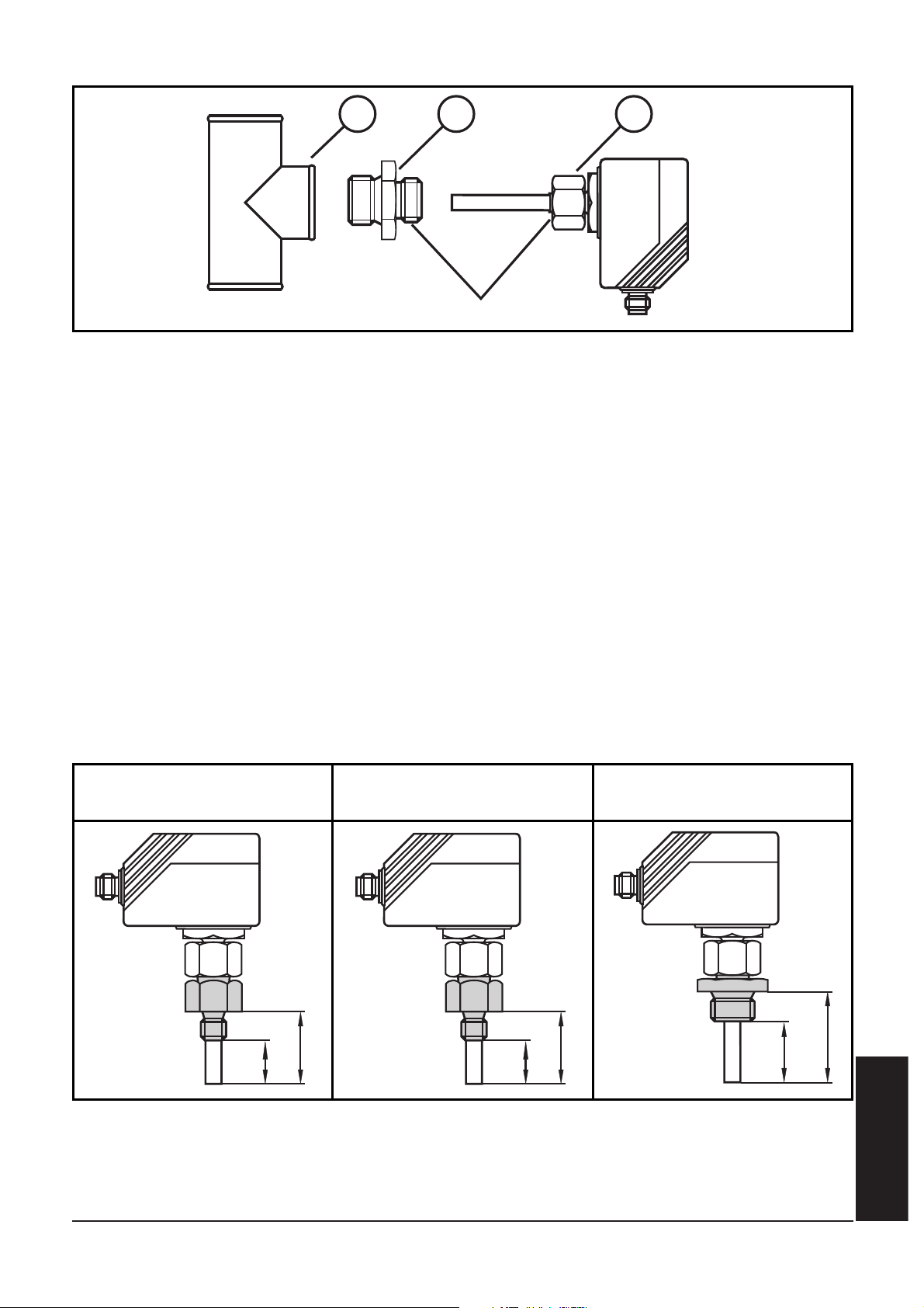
1. Graisser l'écrou (3) et les filetages afin d'assurer que l'écrou peut
être desserré et serré plusieurs fois.
Remarque: Aucune graisse ne doit être appliquée au bout de la
sonde (A).
2. Visser l'adaptateur approprié (2) sur le raccord process (1).
3. Placer le contrôleur de débit sur l'adaptateur et serrer l'écrou (3);
(couple de serrage maxi 50Nm). Maintenir l'appareil dans son orientation.
Profondeur d'installation de la sonde: min. 12mm dans le tube.
L'utilisation de nos accessoires de montage assurent un positionnement correct de la sonde.
Attention: le bout de la sonde ne doit pas toucher la paroi du tube.
FRANÇAIS
43
1 2 3
⎩
⎨
⎧
A
filetage M18 x 1,5
27
13,52713,5
35
21
cote de montage
adaptateur M12
cote de montage
adaptateur G¼
cote de montage
adaptateur G½
Page 42
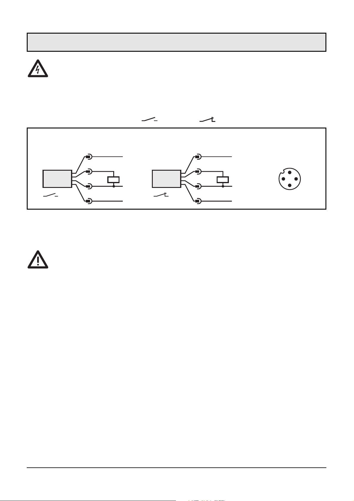
L'appareil doit être monté par un électricien.
Les règlements nationaux et internationaux relatifs à l'installation de matériel électrique doivent être respectés.
Alimentation selon EN50178, TBTS, TBTP.
Mettre l’installation hors tension avant le raccordement.
Schéma de branchement ( = N.O. / = N.F.):
Lorsque la fonction "réglage à distance" est actif:
Utiliser des connecteurs 4 pôles sans shunt entre les broches 2 et 4.
L'utilisation de connecteurs femelles 3 fils avec shunt entre les broches
2 et 4 entraîne le passage de l'appareil en mode autoapprentissage lors
de la commutation de la sortie.
Indication de défaut: Dans le cas d'un court-circuit, l'indication de
fonctionnement et la rampe de LED rouges sont allumées en alternance.
44
P
L
+
2
1
4
3
L-
P
L
+
2
3
4
1
L-
3
1
4
2
WH
BU
BK
BN
WH
BN
BK
BU
branchement
connecteur
(côté capteur)
P = Fil de programmation (pour le réglage à distance)
Couleurs des fils conducteurs des connecteurs femelles ifm:
1 = BN (brun), 2 = WH (blanc), 3 = BU (bleu), 4 = BK (noir).
Raccordement électrique
Page 43
■■
Réglage de la plage de détection débit
HI-Teach
• Le débit du fluide doit être à la valeur maximale souhaité.
• Appuyer sur le bouton Learn/Set pendant >5...<10s (= réglage sur
débit maximum).
Ce réglage suffit pour la plupart des applications à base d'eau.
Option: réglage sur débit minimum (LO-Teach).
• Le débit du fluide doit être à la valeur minimale souhaité (ou débit nul).
• Appuyer sur le bouton Learn/Set pendant >10...<15s (= réglage sur
débit minimum.
■■
Réglage à l'aide du fil de programmation (réglage à distance)
Raccorder le + de l'alimentation à la broche 2 (P) pendant le temps
correspondant.
■■
Réglage du seuil de commutation
• Appuyer brièvement sur le bouton Mode/Enter.
• Appuyer sur le bouton Learn/Set pendant 5s.
• Maintenir le bouton Learn/Set appuyé ou l'appuyer plusieurs fois
jusqu'à ce que le seuil de commutation souhaité soit réglé.
• Appuyer brièvement sur le bouton Mode/Enter.
■■
Surveiller un débit excessif
• Appuyer deux fois sur le bouton Mode/Enter.
• Appuyer sur le bouton Learn/Set pendant 5s, le relâcher lorsque
une LED clignote.
• Appuyer sur le bouton Learn/Set plusieurs fois pour déplacer la LED
indiquant la valeur maximale du débit de fonctionnement.
• Appuyer brièvement sur le bouton Mode/Enter.
FRANÇAIS
45
Programmation
Page 44

■■
Activer / désactiver la fonction "réglage à distance"
• Appuyer trois foi sur le bouton Mode/Enter.
• Appuyer sur le bouton Learn/Set pendant 5s.
• Maintenir le bouton Learn/Set appuyé ou l'appuyer plusieurs fois
jusqu'à ce que la fonction souhaité soit réglé (fonction actif, si les
3 LED à droite et à gauche sont allumées en vert; fonction non
actif, si les 4 LED au milieu sont allumées en rouge).
• Appuyer brièvement sur le bouton Mode/Enter.
■■
Récupérer les réglages de base effectués en usine
• Appuyer sur le bouton Learn/Set pendant >15...<20s.
■■
Pour les réglages, les points suivants sont valables:
• Si lors du réglage, aucun bouton n'est appuyé pendant 15s,
l'appareil redevient opérationnel sans aucune modification des
valeurs.
• Si le réglage est impossible, les LED rouges clignotent. Puis l'appareil redevient opérationnel sans aucune modification des valeurs.
■■
Blocage / Déblocage
L'appareil peut être verrouillé afin d'éviter une fausse programmation
non intentionnelle: Appuyer sur les deux boutons-poussoir pendant
10s (l’appareil doit être en Mode Run). La visualisation s'éteint brièvement (confirmation du blocage / déblocage).
Appareil livré: non bloqué.
Si l'appareil est verrouillé il est possible d'indiquer
• le seuil de commutation actuel (appuyer une fois sur le boutonpoussoir Mode/Enter),
• le réglage de la fonction "surveiller un débit excessif" (appuyer
deux fois sur le bouton-poussoir Mode/Enter),
• le réglage de la fonction "réglage à distance" (appuyer trois fois sur
le bouton-poussoir Mode/Enter).
46
Page 45
Après le montage, le câblage et le réglage vérifier le bon fonctionnement de l'appareil. Dès la mise sous tension toutes les LED s'allument
et s'éteignent l'une après l'autre.* L'appareil est ensuite opérationnel.
*Durant ce temps la sortie est commutée en fonction de la programmation:
ON pour la fonction N.O. et OFF pour la fonction N.F.
Indication de défaut: Dans le cas d'un court-circuit, l'indication de
fonctionnement et la rampe de LED rouges sont allumées en alternance.
Maintenance recommandée: Vérifier périodiquement l’éventuelle
présence de dépôts en bout de sonde. Le cas échéant, les enlever avec
un chiffon doux. Les dépôts adhérant fortement (ex: calcaire) peuvent
être retirés avec un produit acétique de nettoyage usuel.
Données techniques
FRANÇAIS
47
Mise en service / Fonctionnement / Maintenance
Tension d'alimentation [V] . . . . . . . . . . . . . . . . . . . . . . . . . . . 20 ... 36 DC
1
Courant de sortie [mA]. . . . . . . . . . . . . . . . . . . 400; protégé: courts-circuits
protégé: inv. de pol. / protégé contre les surcharges
Chute de tension [V] . . . . . . . . . . . . . . . . . . . . . . . . . . . . . . . . . . . . . < 2,5
Consommation [mA] . . . . . . . . . . . . . . . . . . . . . . . . . . . . . . . . . . . . . < 80
Milieu liquide
Température du fluide [°C]. . . . . . . . . . . . . . . . . . . . . . . . . . . . . -25 ... +80
Plage de réglage des seuils [cm/s] . . . . . . . . . . . . . . . . . . . . . . . . . 3 ... 300
Meilleure sensibilité [cm/s]. . . . . . . . . . . . . . . . . . . . . . . . . . . . . . . . 3 ... 60
Gradient de température maxi du fluide [K/min] . . . . . . . . . . . . . . . . . . 300
Milieu gazeux
Température du fluide [°C]. . . . . . . . . . . . . . . . . . . . . . . . . . . . . -25 ... +80
Plage de réglage des seuils [cm/s] . . . . . . . . . . . . . . . . . . . . . . 200 ... 3000
Meilleure sensibilité [cm/s]. . . . . . . . . . . . . . . . . . . . . . . . . . . . . 200 ... 800
Temps de réponse [s] . . . . . . . . . . . . . . . . . . . . . . . . . . . . . . . . . . . 1 ... 10
Retard à la disponibilité [s] . . . . . . . . . . . . . . . . . . . 15, signalé optiquement
Tenue en pression [bar] . . . . . . . . . . . . . . . . . . . . . . . . . . . . . . . . . . . . 300
Température ambiante [°C] . . . . . . . . . . . . . . . . . . . . . . . . . . . . -25 ... +80
Protection. . . . . . . . . . . . . . . . . . . . . . . . . . . . . . IP 67 (CEI 60529) / (UL50)
Tenue aux chocs [g] . . . . . . . . . . . . . . . . . . . . 50 (DIN / VEI 68-2-27, 11 ms)
Tenue aux vibrations [g] . . . . . . . . . . . . . 20 (DIN / CEI 68-2-6, 55-2000 Hz)
Boîtier . . . . . . . . . . . . . . . . . . . . . . . . . . . . . . . . . . . . . . . . . . . . PBT-GF 20
Matière de la sonde (SI10xx) . . . . . . . . . . . . . . . . . . . . . . . . . . .INOX 316L;
joint torique: FPM 8x1,5 gr 80° Shore A
Matière de la sonde (SI11xx) . . . . . . . . . . . . . . . . . . . . . . . . . . . . . . .titane;
joint torique: FPM 8x1,5 gr 80° Shore A
1)
selon EN50178, TBTS, TPTB
Page 46
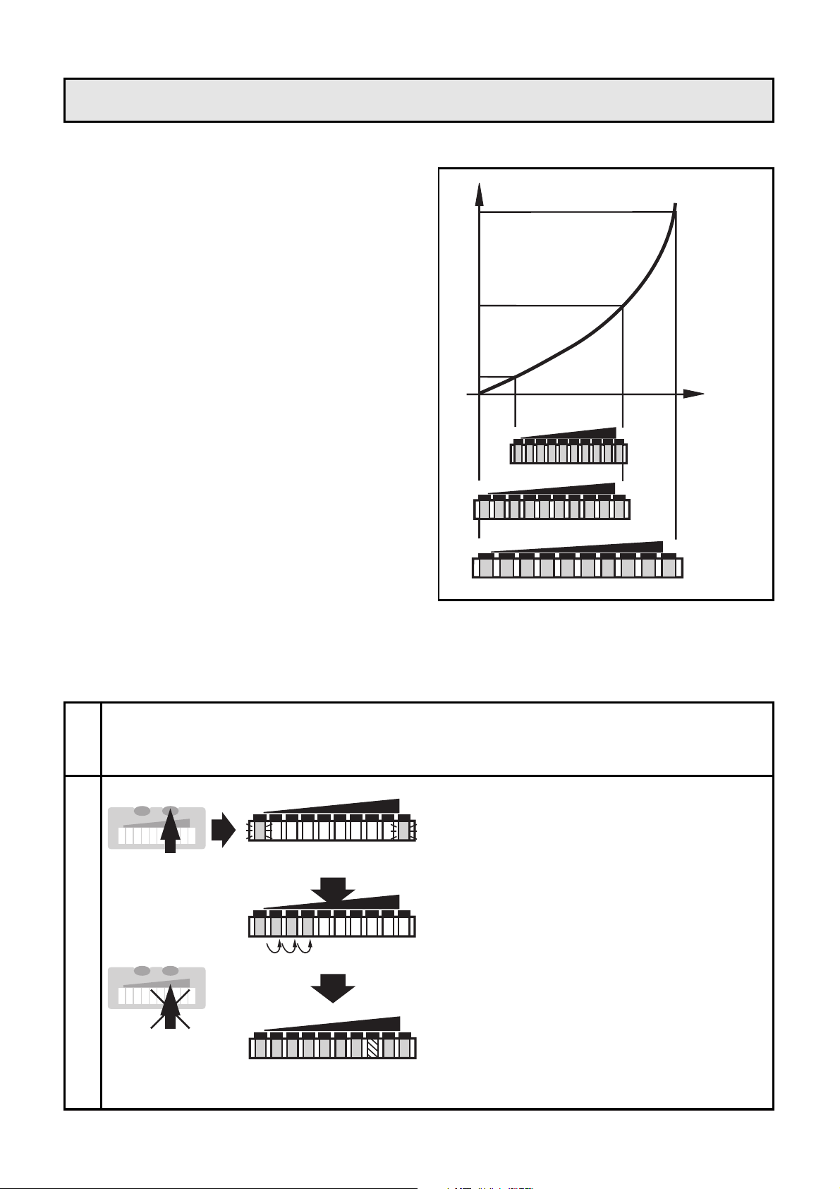
■■
Réglage de la plage de détection débit
La plage de détection est déterminée par:
• Réglage sur débit maximum
souhaité (HI-Teach) .
Ce réglage suffit pour la plupart des applications à base
d'eau.
• De plus: Réglage sur débit
minimum suohaité / nul (LOTeach (optionnel).
• Réglage sur débit maximum (HI-Teach)
L'appareil détecte le débit existant et l'utilise comme valeur maximale
pour l'affichage à LED (LED 9).
48
Diagrammes de réglage / Informations techniques
1
2
Appuyer sur le bouton Learn/Set
et le maintenir appuyé.
Les LED vertes à droite et à
gauche clignotent;
après 5s la rampe de LED
s'allume de gauche à droite
(relâcher le bouton dès que les
premières LED s'allument).
L'affichage s'éteint brièvement.
L'appareil mémorise le débit
existant en tant que débit
maximum et devient opérationnel.
LO HI
LO HI
HILO
>5...<10s
M
S
Mettre l'appareil sous tension.
L'appareil est opérationnel après env. 15s.
Le débit du fluide doit être à la valeur maximale souhaité et constant.
2468103579
LO HI
2468103579
LO HI
2468103579
LO HI
0
vitese de circulation
signal
du
capteur
M
S
Page 47
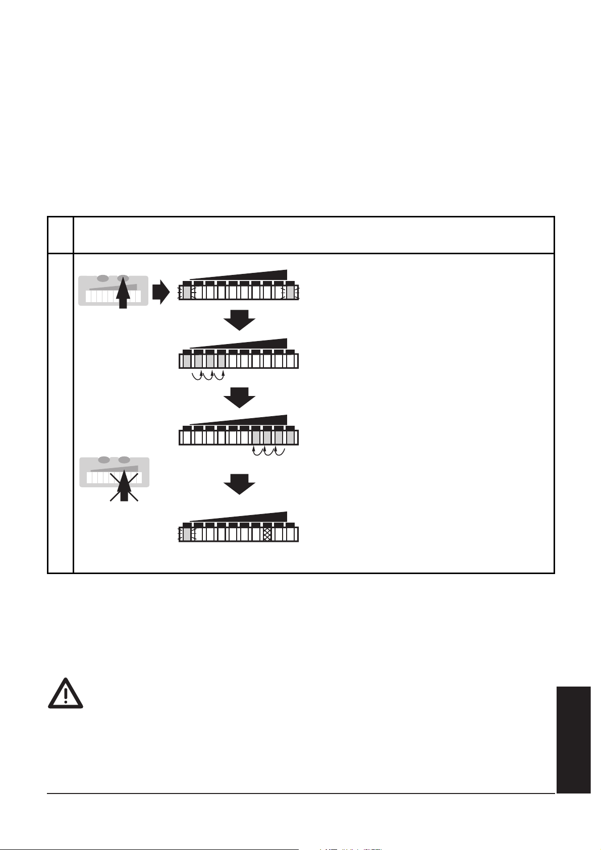
• Réglage sur débit minimum ou débit nul
(LO-Teach; optionnel)
L'appareil détecte le débit existant et l'utilise comme valeur minimale
pour l'affichage à LED. En fonctionnement la première LED verte (LED
0) clignote lorsque le débit du fluide tombe en-dessous de cette valeur
(ou lorsque le débit est nul).
ATTENTION: L'opération LO-Teach doit toujours être effectuée après
l'opération HI-Teach.
• Réglage à l'aide du fil de programmation (réglage à distance)
Raccorder le + de l'alimentation à la broche 2 (P) pendant le temps
correspondant:
>5...<10s (HI-Teach) / >10...<15s (LO-Teach).
FRANÇAIS
49
1
2
Appuyer sur le bouton Learn/Set
et le maintenir appuyé.
Les LED vertes à droite et à
gauche clignotent;
après 5s la rampe de LED
s'allume de gauche à droite,
après 5s supplémentaires la
rampe de LED s'allume de droite
à gauche
(relâcher le bouton dès que les
premières LED à droite
s'allument).
L'affichage s'éteint brièvement.
L'appareil mémorise le débit
existant en tant que débit
minimum et devient opérationnel.
LO HI
LO HI
HILO
LO HI
>10...<15s
M
S
Le débit du fluide doit être à sa valeur minimale souhaité
(ou débit nul) et constant.
Si le + de l'alimentation est raccordé à la broche 2 (P) pendant plus de 15s,
• la fonction “Récupérer les réglages de base” est activée.
Si le + de l'alimentation est raccordé à la broche 2 (P) pendant plus de 20s,
• le nouveau réglage n'est pas mémorisé; l'appareil reprend la surveillance du débit sans modification de la plage de détection;
• l'appareil est verrouillé (les deux boutons-poussoir sont inactifs tant
que le + de l'alimentation reste raccordé à la broche 2).
M
S
Page 48
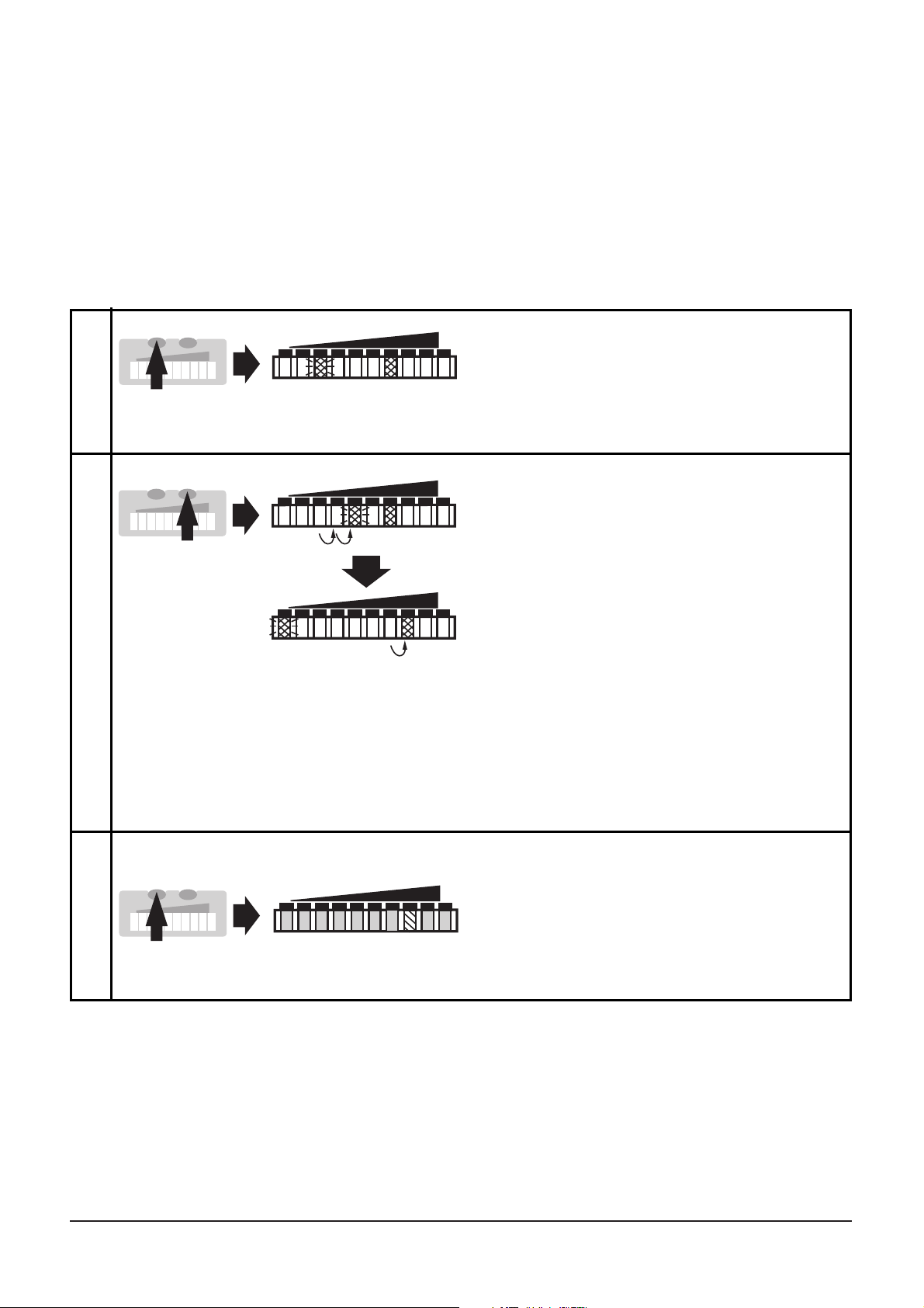
■■
Réglage du seuil de commutation
Le seuil de commutation est préréglé en usine (LED 7). Le réglage
influence le temps de réponse de l'appareil:
• Plus haut est le seuil de commutation = réaction rapide en cas de
chute du débit,
• plus bas est le seuil de commutation = réaction rapide en cas d'augmentation du débit.
50
*Réduire le seuil: Laissez les LED clignotante et allumée passer la valeur de
réglage maximum. Ensuite le cycle recommence à la valeur de réglage
minimum.
**Dépassement: Si la LED clignotante et la LED allumée dépassent la valeur de
réglage maximum, le cycle recommence à la valeur de réglage minimum.
1
2
Appuyer brièvement sur le bouton
Mode/Enter. Le seuil de commutation actuel est affiché:
LED allumée: réglage grossier,
LED clignotante: réglage fin
Appuyer sur le bouton Learn/Set
et le maintenir.
Après 5s le seuil de commutation
est augmenté* (pas à pas en
appuyant sur le bouton-poussoir
plusieurs fois ou continuellement
en le maintenant appuyé).
Indication:
La LED clignotante passe de
gauche à droite. Lorsque la LED
clignotante atteint la position 9,
elle retourne à la LED 0 et la LED
qui est constamment allumée
avance d'un pas.**
LO HI
LO HI
LO HI
1 x
M
S
M
S
3
Appuyer sur le bouton Mode/Enter
brièvement (confirmation).
L'affichage s'éteint brièvement.
Le seuil de commutation réglé
devient effectif; l'appareil devient
opérationnel.
HILO
M
S
>5s
Page 49
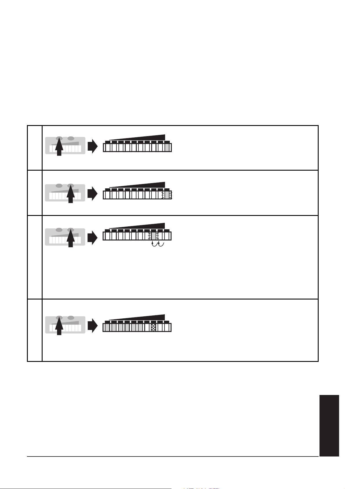
■■
Surveiller un débit excessif
Grâce à cette fonction, une fenêtre d'affichage dans la plage de
détection peut être définie: Déplacer la LED indiquant la valeur maximale à la position 8, 7, 6 ou 5. En débit maximum toutes les LED de
cette échelle sont allumées. Les LED au-dessus de cette échelle signalent un débit excessif.
Si le seuil de commutation est supérieur à cette échelle, l'appareil
commute en cas de débit excessif.
Remarque:
Après chaque réglage sur débit maximum (HI-Teach), la valeur d'affichage
déplacée est repositionnée (à la LED 9).
FRANÇAIS
51
1
2
Appuyer deux fois sur le bouton
Mode/Enter.
Le réglage actuel est affiché (LED
verte).
Appuyer sur le bouton Learn/Set
pendent 5s (jusqu'à ce que la LED
clignote).
LO HI
LO HI
2 x
M
S
M
S
3
Appuyer sur le bouton Learn/Set
plusieurs fois jusqu'à ce que la LED
désirée clignote (LED 8, 7, 6 ou 5).
Après chaque pression sur le
bouton la LED recule d'un pas.
Lorsque la LED 5 est atteinte, une
nouvelle pression permet le retour
à la LED 9.
LO HI
M
S
4
Appuyer sur le bouton
Mode/ Enter brièvement
(confirmation).
L'affichage s'éteint brièvement.
L'appareil mémorise le nouveau
réglage et devient opérationnel.
HI
LO
M
S
5s
Page 50
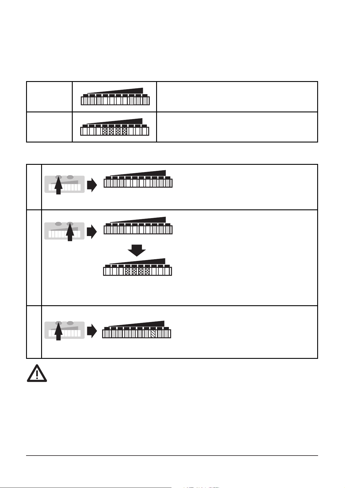
■■
Activer / désactiver la fonction "réglage à distance"
Si la fonction est active, l'appareil peut être réglé en raccordant le +
de l'alimentation à la broche 2.
Appareil livré: fonction actif.
Lorsque la fonction "réglage à distance" est actif,
...le raccordement du + de l'alimentation à la broche 2 (P) pendant plus
de 20s entraîne le verrouillage de l'appareil: les boutons-poussoir
deviennent inactifs et le restent durant tout le temps de raccordement
du + de l'alimentation à la broche 2 (P).
... utiliser des connecteurs 4 pôles sans shunt entre les broches 2 et 4.
L'utilisation de connecteurs femelles 3 fils avec shunt entre les broches
2 et 4 entraîne le passage de l'appareil en mode autoapprentissage lors
de la commutation de la sortie.
52
Fonction
actif
Les 4 LED au milieu sont allumées en
rouge.*
HILO
Fonction
non actif
Les 3 LED à droite et à gauche sont
allumées en vert.*
LO HI
1
2
Appuyer sur le bouton-poussoir
Mode/Enter trois fois.
Le réglage actuel est indiqué.
Appuyer sur le bouton-poussoir
Learn/Set et le maintenir appuyé,
après 5s la fonction change.
(Après chaque nouvelle pression
sur le bouton Learn/Set la
fonction change de nouveau).
HILO
HILO
LO HI
3 x
M
S
>5s
M
S
3
Appuyer brièvement sur le bouton
Mode/Enter (= confirmation).
L'affichage s'éteint brièvement,
ensuite l'appareil devient opérationnel.
HILO
M
S
*Les LED clignotent lorsque le + de l'alimentation est raccordé à la broche 2 (P).
Page 51
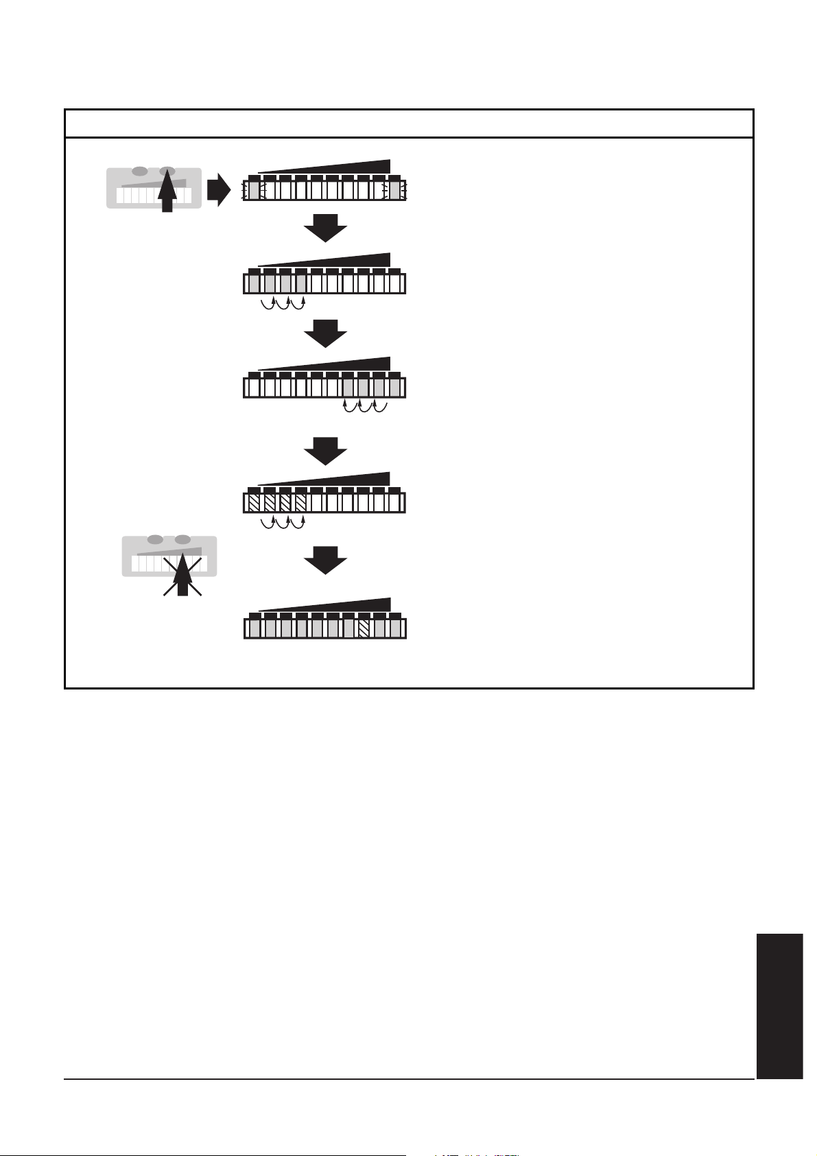
■■
Récupérer les réglages de base effectués en usine
FRANÇAIS
53
Appuyer sur le bouton Learn/Set
et le maintenir appuyé.
Les LED vertes à droite et à gauche
clignotent;
après 5s la rampe de LED s'allume
de gauche à droite,
après 5s supplémentaires la
rampe de LED s'allume de droite
à gauche,
L'affichage s'éteint brièvement.
Tous les réglages effectués en
usine sont récupérés, l'appareil
devient opérationnel.
LO HI
LO HI
HILO
LO HI
après 5s supplémentaires la
rampe de LED (orange) s'allume
de gauche à droite
(relâcher le bouton dès que les
premières LED orange s'allument).
LO HI
>15...<20s
M
S
M
S
S'assurer d'être dans le mode Run débit.
Page 52
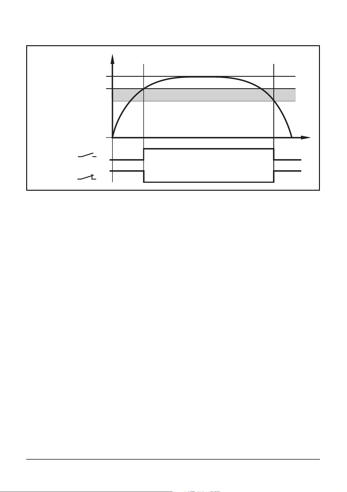
Fonction hystérésis
Si le débit augmente, la sortie commute lorsque le seuil de commutation (SP) est atteint.
Si le débit diminue de nouveau, la sortie ne commute que lorsque la
valeur “SP minus hystérésis” est atteinte.
L'hystérésis est considérablement influencée par le choix de la plage
de fonctionnement sur la courbe de sensibilité de la sonde:
• Dans le cas de réglage sur les valeurs HI-Flow dans la plage 0 ... 60cm/s
l'hystérésis est 2 - 4cm/s (valeurs s'appliquant à l'eau).
• Dans le cas de réglage sur les valeurs HI-Flow supérieures à
100 cm/s l'hystérésis augmente lorsque le débit augmente.
Le temps de réponse typique de l'appareil est 3 ... 8s. Il peut être
influencé par le réglage du LO-Teach et du seuil de commutation.
• Plus bas est réglé le LO-Teach ou le seuil de commutation, plus vite
l'appareil indiquera débit.
• Plus haut est réglé le LO-Teach ou le seuil de commutation, plus vite
l'appareil indiquera non débit.
54
OUT
t
1
0
1
0
OUT
débit maximum
débit
seuil de
commutation (SP)
débit minimum
Hystérésis
 Loading...