

Page 1
Operating instructions
Mechatronic flow sensor
SBY357
704561 / 04 09 / 2010
UK
Page 2

2
1 Safety instructions
• Please read the product description prior to set-up of the unit. Ensure that the
product is suitable for your application without any restrictions.
• Improper or non-intended use may lead to malfunctions of the unit or to
unwanted effects in your application. That is why installation, electrical connection, set-up, operation and maintenance of the unit must be carried out by
qualified personnel authorised by the plant operator.
• Check the compatibility of the product materials (see technical data) with the
media to be monitored in all applications.
• The device shall be supplied from an isolating transformer having a secondary
Listed fuse rated either
a) max 5 amps for voltages 0~20 V (0~28.3 Vpeak), or
b) 100/Vp for voltages of 20~30 V (28.3~42.4 Vpeak).
• Flow Operated Switches shall be connected only by using any R/C (CYJV2)
cord, having suitable ratings.
Contents
1 Safety instructions ...............................................................................................2
2 Functions and features ........................................................................................3
3 Installation............................................................................................................3
4 Electrical connection ............................................................................................4
5 Switch point setting ..............................................................................................4
5.1 Definition of requested value .........................................................................5
5.2 Adjustment to existing flow ............................................................................5
6 Operation .............................................................................................................6
7 Maintenance, repair and disposal ........................................................................6
8 Scale drawing ......................................................................................................7
9 Technical data .....................................................................................................8
Page 3
3
UK
2 Functions and features
The unit monitors liquid media (water, glycol solutions, oils).
It detects the volumetric flow quantity to the principle of differential pressure and
switches the output:
• Output closed (LED = ON), if volumetric flow quantity ≥ switch point.
• Output open (LED = OFF), if volumetric flow quantity < switch point.
The switch point is adjustable.
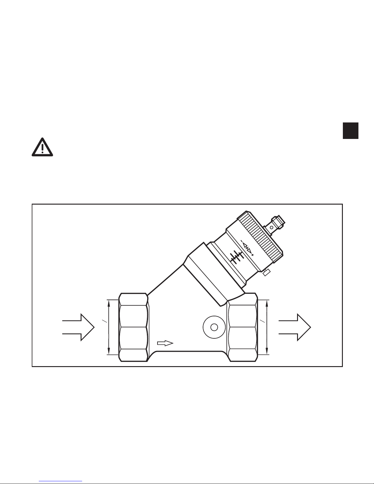
3 Installation
► Ensure that the system is free of pressure during installation.
► Ensure that no media can leak at the mounting location during installa-
tion.
► Install the unit according to the marked flow direction into a pipe RP 1½ and
tighten firmly.
Rp 1
2
1
Rp 1
2
1
IN
OUT
IN = inlet
OUT = outlet
Page 4

4
4 Electrical connection
The unit must be connected by a qualified electrician.
The national and international regulations for the installation of electrical
equipment must be adhered to.
Voltage supply to EN 50178, SELV, PELV.
► Disconnect power.
► Connect the unit as follows:
For information about available sockets/connectors see:
www.ifm.com
→ Products → Accessories
5 Switch point setting
There are 2 possibilities:
• Definition of requested value → 5.1.
• Adjustment to existing flow → 5.2.
A
B
C
D
1 2
A: LED; B: setting screw; C: lock screw; D: setting scale
Do not turn the setting screw beyond the maximum value of the setting
range (→ Technical data) to avoid faulty switching.
Page 5

5
UK
5.1 Definition of requested value
► Loosen the lock screw.
► Turn the setting screw until the requested value just becomes visible on the
setting scale. → Example in figure 2: requested value = 100 l/min.
► Tighten the lock screw.
5.2 Adjustment to existing flow
► Let the normal flow circulate in the installation.
► Loosen the lock screw.
► Set the switch point with the setting screw.
- If the LED lights before setting: turn the setting screw in the direction [+] until
the LED goes out. Then turn in the opposite direction [-] until the LED lights.
- If the LED does not light before setting: turn the setting screw in the direction
[-] until the LED lights.
► Tighten the lock screw.
Correlation between number of the turns of the setting screw (SET) and switch
point in l/min:
One complete turn corresponds to approx. 18 l/min
SET
1 2 3 4 5 6 7 8 10
0
20
40
60
80
100
Q [l/min]
120
11 12 13 14
140
160
180
200
The diagram shows the typical course of the measurement curves for water at 20 °C.
Page 6

6
6 Operation
After power on the unit is ready for operation. It detects the volumetric flow quantity and switches the output according to the setting.
Function diagram
A = requested flow; B = switch point; C = switching output
7 Maintenance, repair and disposal
In case of correct use no maintenance and repair measures are necessary.
In case of strongly polluted media: mount a filter in front of the inlet (IN). Recommendation: use a 50-micron filter.
Only the manufacturer is allowed to repair the unit.
After use dispose of the unit in an environmentally friendly way in accordance with
the applicable national regulations.
Page 7

7
UK
8 Scale drawing
56
137...146,5
121,5
121...127,5
Rp 1
2
1
Rp 1
2
1
20 20
dimensions are in millimeters
Page 8

8
9 Technical data
Setting range [l/min]..................................................................................................20...200
Flow range max. [l/min] ...................................................................................................200
Operating voltage [V] ....................................................................... 24 DC (-15 % / +10 %)
Current rating [mA] ......................................................................................................... 100
Protected against short circuits, reverse polarity and overload
Voltage drop [V] .............................................................................................................< 2.5
Current consumption [mA] ..............................................................................................< 15
Hysteresis [l/min] ..........................................................................................................5...10
Repeatability [% of value of measuring range] ....................................................................1
Accuracy [% of value of measuring range] .......................................................................± 5
Response time [s] ........................................................................................................< 0.01
Pressure loss (dP) / flow rate (Q)
dP [bar]
Q [l/min]
5
15
25
35
45
55
65
75
85
95
105
115
125
135
145
155
165
175
185
195
2050
0,1
0,2
0,3
0,4
0,5
0,6
0,7
0,8
0
Housing materials ......................brass chemically nickel-plated; aluminium anodised; POM
Materials (wetted parts) .............. stainless steel (304S15); brass; chemically nickel-plated;
POM; PPS; O-ring: FPM (Viton)
Protection ............................................................................................................... IP 67 III
Switching cycles min. ........................................................................................... 10 million
Medium temperature [°C] ........................................................................................... 0...85
Operating temperature [°C] ........................................................................................ 0...60
Pressure resistance [bar].................................................................................................. 25
Further information at www.ifm.com
 Loading...