

Page 1

Device manual
Encoder with CANopen
interface
RM7xxx
RN7xxx
UK
704434/01 08 / 2010
Page 2

CANopen encoder
Contents
1 Preliminary note � � � � � � � � � � � � � � � � � � � � � � � � � � � � � � � � � � � � � � � � � � � � � � � � � 4
1�1 Symbols used� � � � � � � � � � � � � � � � � � � � � � � � � � � � � � � � � � � � � � � � � � � � � � � 4
1�2 Warning signs used � � � � � � � � � � � � � � � � � � � � � � � � � � � � � � � � � � � � � � � � � � 4
2 Safety instructions � � � � � � � � � � � � � � � � � � � � � � � � � � � � � � � � � � � � � � � � � � � � � � � 4
3 General information � � � � � � � � � � � � � � � � � � � � � � � � � � � � � � � � � � � � � � � � � � � � � � 5
3�1 Absolute encoders � � � � � � � � � � � � � � � � � � � � � � � � � � � � � � � � � � � � � � � � � � � 5
3�2 CANopen technology � � � � � � � � � � � � � � � � � � � � � � � � � � � � � � � � � � � � � � � � 5
3�2�1 Certification of CANopen products� � � � � � � � � � � � � � � � � � � � � � � � � � � 5
3�3 References � � � � � � � � � � � � � � � � � � � � � � � � � � � � � � � � � � � � � � � � � � � � � � � � � 5
3�3�1 Abbreviations � � � � � � � � � � � � � � � � � � � � � � � � � � � � � � � � � � � � � � � � � � � 6
4 Installation of the encoder� � � � � � � � � � � � � � � � � � � � � � � � � � � � � � � � � � � � � � � � � � 6
4�1 Settings of the encoder � � � � � � � � � � � � � � � � � � � � � � � � � � � � � � � � � � � � � � � 6
4�2 Node address � � � � � � � � � � � � � � � � � � � � � � � � � � � � � � � � � � � � � � � � � � � � � � � 7
4�3 Bus termination � � � � � � � � � � � � � � � � � � � � � � � � � � � � � � � � � � � � � � � � � � � � � 7
4�4 Baud rate switch� � � � � � � � � � � � � � � � � � � � � � � � � � � � � � � � � � � � � � � � � � � � � 7
4�5 Electrical connection of the encoder � � � � � � � � � � � � � � � � � � � � � � � � � � � � � 8
4�6 BUS lines � � � � � � � � � � � � � � � � � � � � � � � � � � � � � � � � � � � � � � � � � � � � � � � � � � 9
4�7 Shield � � � � � � � � � � � � � � � � � � � � � � � � � � � � � � � � � � � � � � � � � � � � � � � � � � � � 10
4�8 EDS file � � � � � � � � � � � � � � � � � � � � � � � � � � � � � � � � � � � � � � � � � � � � � � � � � � 10
4�9 Parameter setting � � � � � � � � � � � � � � � � � � � � � � � � � � � � � � � � � � � � � � � � � � � 10
4�10 LED display � � � � � � � � � � � � � � � � � � � � � � � � � � � � � � � � � � � � � � � � � � � � � � �11
4�10�1 Module LED � � � � � � � � � � � � � � � � � � � � � � � � � � � � � � � � � � � � � � � � � � �11
4�10�2 Status LED� � � � � � � � � � � � � � � � � � � � � � � � � � � � � � � � � � � � � � � � � � � 12
5 Profile overview � � � � � � � � � � � � � � � � � � � � � � � � � � � � � � � � � � � � � � � � � � � � � � � � 12
6 Functionality of the encoder � � � � � � � � � � � � � � � � � � � � � � � � � � � � � � � � � � � � � � � 13
6�1 Basic functionality of the encoder� � � � � � � � � � � � � � � � � � � � � � � � � � � � � � � 13
6�2 Default identifiers � � � � � � � � � � � � � � � � � � � � � � � � � � � � � � � � � � � � � � � � � � � 13
6�3 Boot message � � � � � � � � � � � � � � � � � � � � � � � � � � � � � � � � � � � � � � � � � � � � � 14
6�4 Operating parameters � � � � � � � � � � � � � � � � � � � � � � � � � � � � � � � � � � � � � � � 15
6�5 Scaling function � � � � � � � � � � � � � � � � � � � � � � � � � � � � � � � � � � � � � � � � � � � � 15
6�5�1 Overview � � � � � � � � � � � � � � � � � � � � � � � � � � � � � � � � � � � � � � � � � � � � � 15
6�5�2 Scaling formulas � � � � � � � � � � � � � � � � � � � � � � � � � � � � � � � � � � � � � � � 16
6�6 Preset value � � � � � � � � � � � � � � � � � � � � � � � � � � � � � � � � � � � � � � � � � � � � � � � 16
6�6�1 Overview � � � � � � � � � � � � � � � � � � � � � � � � � � � � � � � � � � � � � � � � � � � � � 16
6�6�2 Calculation of the preset value� � � � � � � � � � � � � � � � � � � � � � � � � � � � � 17
6�7 Zero setting � � � � � � � � � � � � � � � � � � � � � � � � � � � � � � � � � � � � � � � � � � � � � � � 18
6�8 Speed and acceleration � � � � � � � � � � � � � � � � � � � � � � � � � � � � � � � � � � � � � � 18
6�9 PDO mapping� � � � � � � � � � � � � � � � � � � � � � � � � � � � � � � � � � � � � � � � � � � � � � 18
6�9�1 PDO configuration � � � � � � � � � � � � � � � � � � � � � � � � � � � � � � � � � � � � � � 19
6�9�2 PDO configuration example � � � � � � � � � � � � � � � � � � � � � � � � � � � � � � � 20
6�10 Heartbeat � � � � � � � � � � � � � � � � � � � � � � � � � � � � � � � � � � � � � � � � � � � � � � � � 21
6�11 IRT mode � � � � � � � � � � � � � � � � � � � � � � � � � � � � � � � � � � � � � � � � � � � � � � � � 21
2
Page 3

CANopen encoder
6�11�1 Diagnosis of the encoder � � � � � � � � � � � � � � � � � � � � � � � � � � � � � � � � 22
6�11�2 Operating status � � � � � � � � � � � � � � � � � � � � � � � � � � � � � � � � � � � � � � 22
6�12 Alarms and warnings � � � � � � � � � � � � � � � � � � � � � � � � � � � � � � � � � � � � � � � 22
7 Manufacturer-specific objects� � � � � � � � � � � � � � � � � � � � � � � � � � � � � � � � � � � � � � 23
7�1 Object 0x5003, speed type� � � � � � � � � � � � � � � � � � � � � � � � � � � � � � � � � � � � 23
7�2 Object 0x5A03, serial number 2 � � � � � � � � � � � � � � � � � � � � � � � � � � � � � � � � 24
8 Example encoder configuration � � � � � � � � � � � � � � � � � � � � � � � � � � � � � � � � � � � � 24
UK
Licences and trademarks
Microsoft
Adobe
All trademarks and company names are subject to the copyright of the respective companies�
®
, Windows®, Windows XP® and Windows Vista® are registered trademarks of Microsoft Corporation�
®
and Acrobat® are registered trademarks of Adobe Systems Inc�
3
Page 4

CANopen encoder
Preliminary note1
Symbols used1.1
► Instruction
> Reaction, result
[…] Designation of pushbuttons, buttons or indications
→ Cross-reference
Important note
Non-compliance can result in malfunctions or interference�
Information
Supplementary note
Warning signs used1.2
ATTENTION
Warning of damage to property�
Safety instructions2
This manual is part of the device� It contains information and illustrations about the
correct handling of the device and must be read before installation or use�
Observe the operating instructions�
Non-observance of the instructions, operation which is not in accordance with use
as prescribed below, wrong installation or handling can affect the safety of people
and machinery�
The installation and connection must comply with the applicable national and
international standards� Responsibility lies with the person installing the unit�
Only the signals indicated in the technical data or on the device label may be
supplied to the connections or wires�
4
Page 5

CANopen encoder
General information3
Absolute encoders3.1
For an absolute encoder each angular position is assigned a coded position value�
This is generated by a coded disc with several parallel fine code segments which
are detected individually� For singleturn encoders, i�e� an encoder producing
absolute positions within one revolution, the absolute position information is
repeated with every revolution� A multiturn encoder can also distinguish between
revolutions via a gearbox containing magnets which are individually detected
by Hall elements� The number of the individual revolutions is determined by the
resolution of the multiturn detection and is repeated after the total resolution has
been reached�
CANopen technology 3.2
The CANopen communication profile is based on the CAN Application Layer
(CAL) specification from CiA (CAN in Automation)� CANopen is considered as a
robust fieldbus with highly flexible configuration options� It is used in many various
applications which are based on different application profiles� CANopen comprises
a concept to configure and communicate real-time data using synchronous and
asynchronous messages� Four message types (objects) are distinguished�
UK
Administration messages (layer management, network management and 1�
identifier distribution)
Service data messages (SDO)2�
Process data messages (PDO)3�
Predefined messages (synchronisation, time stamp, emergency)4�
You can find more information in the CANopen specification�
Certication of CANopen products3.2.1
To achieve interoperability and a suitable device functionality CANopen products
are approved by external notified bodies� A copy of the certificate is attached to
this manual�
References3.3
http://www�can-cia�org
CAN Application Layer, DS 201…207 CiA
CAL based communication profile, DS 301 CiA
Device profiles for encoders, DS 406 CiA
CAN specification version 2�0 A Robert Bosch GmbH
CANary CAN controller Atmel
5
Page 6
CANopen encoder
Abbreviations3.3.1
CAN Controller Area Network
CiA CAN in Automation
CAL CAN Application Layer
EDS Electronic Data Sheet
DCF Device Configuration File
SDO Service Data Object
PDO Process Data Object
TPDO Transmit PDO
COB-ID Communication Object Identifier
NMT Network Management
IRT Isochronous Real Time
Installation of the encoder4
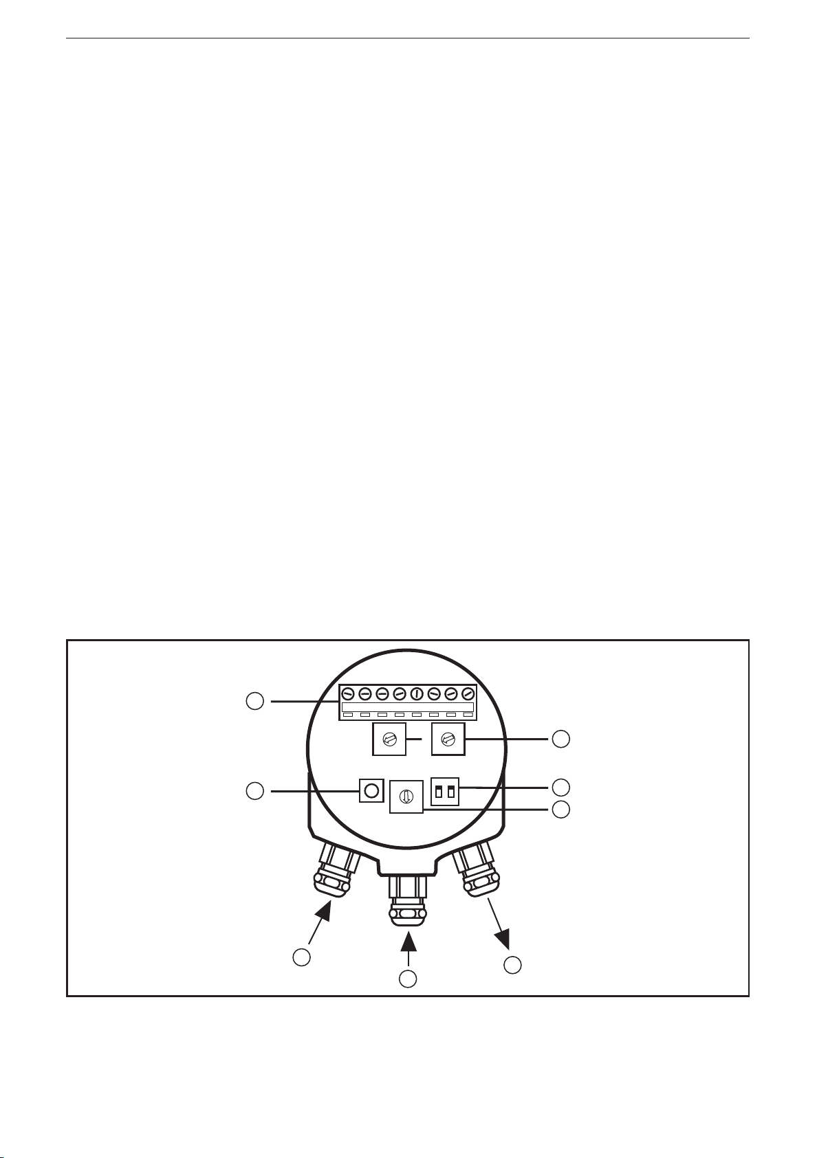
Settings of the encoder4.1
The node address of the encoder, the baud rate and the bus termination must be
configured during the set-up of the device� This is done by removing the cover of
the housing on the back�
switches node address1:
bus termination on/off2:
baud rate switch3:
bus output4:
bus input5:
6
Page 7

CANopen encoder
supply +U6:
zero set button7:
screw terminals for bus and power supply connection8:
B
Node address4.2
The node address of the device can be set via two decimal rotary switches in
the device� The step increment x10 and x1 is specified next to the switches�
The permitted address range is between 3 and 98� The address range 0 to
2 is reserved for the master� Address 0 is used for broadcasting, i�e� master
broadcasting to multiple slaves� Note that each address used in a CANopen
network must be unique and must not be used by other devices�
The device address is read and adopted when the encoder power supply is
switched on (or the NMT command Reset_Communication or Reset_Node)� Both
actions are required to adopt changes to the address settings�
Bus termination4.3
In a CANopen network all devices are connected in a bus structure� Up to 32
devices (masters and/or slaves) can be connected in one segment� If more
devices are needed, repeaters must be used to amplify the signals between the
segments� An active termination must be added at the beginning and end of each
bus segment to ensure an error-free operation� These terminations are integrated
into the device and can be activated via DIP switches�
UK
The active termination is only activated if the encoder is switched on� If the device
is switched off, the CAN_H and CAN_L lines are internally terminated by a 121 Ω
resistor�
Bit 1 Bit 2 Effect
on on 121 ohm resistor between CAN_H and CAN_L
on off no valid setting
off on no valid setting
off off no resistor between CAN_H and CAN_L
Baud rate switch4.4
The communication baud rate can be set using the rotary switch inside the
encoder� The baud rate is set according to the following table�
7
Page 8
CANopen encoder
�
Settings baud rate switch
Baud rate [kbits] Baud rate switch
10 0
20 1
50 2
125 3
250 4
500 5
800 6
1000 7
400 8
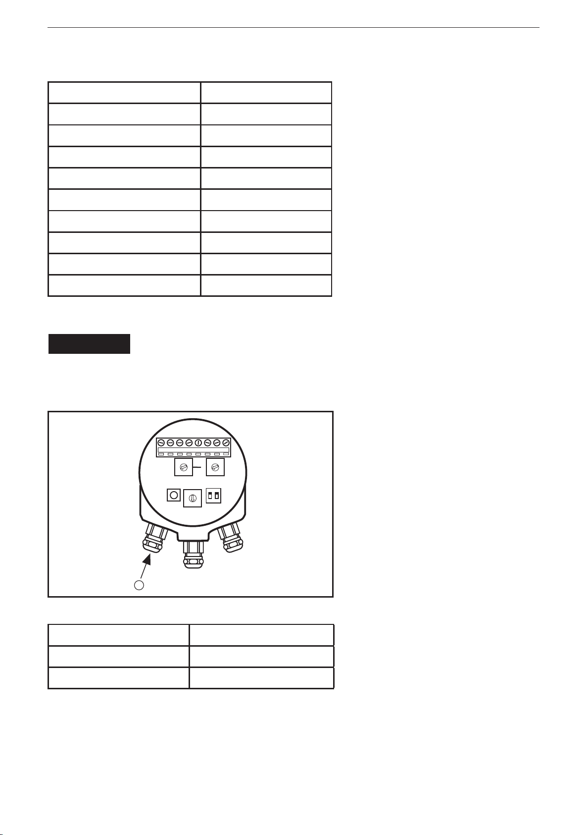
Electrical connection of the encoder4.5
NOTE
The unit must be connected by a qualified electrician�
Disconnect power before connecting the unit�
Voltage supply U1:
B
Function Terminal
+U
(9���36 V DC) +
B
0 V -
The cable glands of the encoder must always be equipped with a shielded
power supply cable with a wire cross-section between 0�34 mm2 and 1�5 mm2�
The permissible outer cable diameter is ø 8���ø 10 mm� Two screw terminals
with the required power supply terminals marked (+) and (-) are located inside
the cover�
8
Page 9
CANopen encoder
The (+) terminal is used for the connection to the +UB line (9���36 V DC)� The (-)
terminal is used for the connection to the 0 V line�
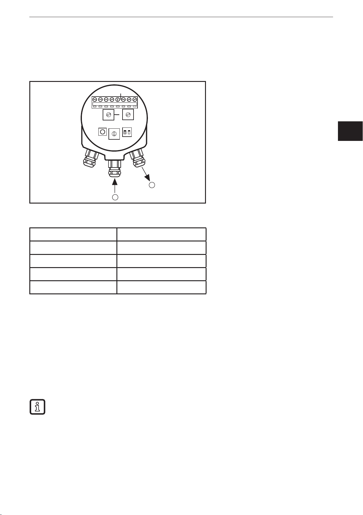
BUS lines4.6
UK
bus output1:
bus input2:
Function Terminal
CAN shield cable gland
CAN GND G
CAN_H H
CAN_L L
The cable glands of the encoder must be equipped with a twisted pair cable
according to EN50170� The guidelines recommend a wire cross-section > 0�34
mm2�� The permissible outer cable diameter is ø 6 ��� to ø 8 mm� Six screw
terminals with the required bus line terminals marked H, L and G are in the
terminal chamber�
Connect the (H) terminal to the CAN_H cable� ►
Connect the (L) terminal to the CAN_L cable� ►
Connect the (G) terminal to the CAN_G cable� ►
The G, H and L terminals are internally connected to each other so that
the bus cables can be connected to any pair�
9
Page 10

CANopen encoder
Shield4.7
To achieve the highest possible noise immunity and electromagnetic compatibility
the bus and power supply cables must always be shielded� The shield must be
connected to ground on both ends of the cable� In certain cases a compensation
current can flow across the shield� Therefore a compensation wire for the potential
is recommended�
EDS file4.8
An EDS file can be downloaded from our website:
→
www�ifm�com
Contents of the EDS file:
communication functions and objects as defined in the CANopen ●
communication profile DS-301
device-specific objects as defined in the encoder profile DS-406 ●
manufacturer-specific objects ●
The EDS file serves as a template for different configurations of a device type� A
DCF file is generated by the EDS file and describes a specific configuration of the
device including object values, selected baud rate and module ID�
CANopen configuration tools are available to support the CANopen network
configuration and the device configuration via the CAN bus� The information about
the device is in the EDS file�
The EDS installation process depends on your configuration tool� In case of
problems please contact your controller supplier�
Parameter setting4.9
If the device is in the pre-operational status, the parameters are set by the
configuration tool using the objects in the EDS file� During runtime the parameters
can also be changed (operating status)�
10
Page 11

CANopen encoder
The position data is directly affected by some parameters and changes
directly after such a parameter message�
Only change scaling function parameters and the code sequence if the shaft is ►
stationary�
The parameter setting process depends on your configuration tool� In case
of problems please contact your controller supplier�
LED display4.10
Two LEDs are on the cover of the encoder to indicate the encoder status� The
module LED indicates the status of the module itself� The status LED indicates the
module status on the bus�
UK
The LEDs can be permanently on or out, blink or flash�
Blinking: LED 200 ms on, 200 ms out
Flashing: LED 200 ms on, 1000 ms out (single flashing)
LED 200 ms on, 200 ms out, 200 ms on, 1000 ms out (double flashing)
Module LED4.10.1
The module LED is a two-colour LED with the following functionality:
LED Display
out no voltage supply
green voltage supply ok
red position error, the encoder cannot provide a
correct position value
3 x blinking green, out zero set button pressed and position set to
zero
after blinking three times the LED automatically returns to the previous status
red blinking wrong switch settings
11
Page 12

CANopen encoder
Status LED4.10.2
The status LED is a two-colour LED with two functions; a green LED (run status)
and a red LED (error status)�
LED Display
green flashing encoder in the NMT status operational
green blinking encoder in the NMT status stopped
green lighting encoder in the NMT status pre-operational
red out no error
red blinking overflow on the error counter
red double blinking guard event or heartbeat event occurred
red lights the encoder is in the bus off status
If the communication of the encoder is error free in the operating status, the
module LED shows green and the status LED flashes green�
Profile overview5
The encoder profile defines the functions of the encoders connected to CANopen�
The operating functions are divided in two device classes:
Class 1
The mandatory class with basic functions which all encoders must support� As an
option, class 1 encoders can support selected functions of class 2� However, these
functions must be implemented according to the profile�
Class 2
The encoder must support all functions of class 1 as well as all functions defined in
class 2�
Functions of class 2
Transmission of the absolute position value with polling, cyclic or SYNC mode� ●
Speed and acceleration output values ●
Change of the code sequence ●
Presettings ●
Scaling of the encoder resolution ●
Advanced diagnosis
Encoder identification ●
Operating status ●
Operating time ●
12
Page 13

CANopen encoder
Alarms and warnings ●
All programming and diagnostic parameters can be accessed via SDOs� The
output position value of the encoder is represented in binary format�
Functionality of the encoder6
Basic functionality of the encoder6.1
The figure below gives an overview of the basic functions of the encoder and how
they are implemented in the encoder�
Physical position
← code sequence
UK
Basic function
Absolute position
Scaling function
Preset function ← preset value
Output position value
Default identifiers6.2
In order to facilitate configuration a default identifier allocation scheme is defined
for CANopen devices� This ID allocation scheme consists of a functional part
which determines the object priority and a module ID part which is equal to the
node number (1 to 127)� Broadcasting of non confirmed services (NMT and SYNC)
is indicated by a module ID of zero�
→ singleturn resolution
→ number of distinguishable revolutions
↔ steps per revolution
↔ total measuring range in steps
↔ scaling function control/status
→ offset value
For CANopen the 11-bit identifier is set up as follows:
bit no� 0���6 node number
bit no� 7���10 function code
Bit
no.
10 9 8 7 6 5 4 3 2 1 0
function code node number
13
Page 14

CANopen encoder
The following broadcast objects with default identifiers are available in the
encoder:
Object Function
code (binary)
Resulting identifier (COBID)
Priority group
NMT 0000 0 0
SYNC 0001 128 0
The following peer-to-peer objects with default identifiers are available in the
encoder:
Object Function code
(binary)
Resulting
identifier (COB-ID)
Priority group
EMERGENCY 0001 129���255 0, 1
PDO1 (tx) 0011 385���511 1, 2
PDO2 (tx) 0101 641���767 2, 3
SDO (tx) 1011 1409���1535 6
SDO (rx) 1100 1537���1663 6, 7
Node guard 1110 1793���1919 -
Boot message6.3
The encoder transmits a boot message after power on and initialisation� This
message uses the default emergency identifier and has no data bytes� With
this message the user can retrieve the transmitting node directly from the used
identifier (COB-ID) as this is a function of the node number → chapter 6.2.
14
Page 15

CANopen encoder
Operating parameters 6.4
Object 6000h, operating parameters, controls the functions for code sequence and
scaling�
Bit Function Bit = 0 Bit = 1 Class 1 Class 2
0 code sequence CW CCW M M
2 scaling function
control
switched off enabled
O M
UK
4���11 reserved for further use
12���15 manufacturer-
specific parameters
no
indication
no
indication
O O
The code sequence defines whether increasing or decreasing position values are
provided when the encoder shaft rotates clockwise or counterclockwise (seen on
the shaft)� The control of the scaling function is used for enabling/disabling the
steps per revolution in the object (6001h) and for the complete measuring range in
steps in the object (6001h) (→ chapter 6.5).
If the scaling function bit is set, the scaling parameters affect the output position
value� If the scaling function bit is set to 0, the scaling function is disabled�
Scaling function6.5
Overview6.5.1
With the scaling function the internal numerical value of the encoder is converted
in the software to change the physical resolution of the encoder� The parameters
"steps per revolution" (object 0x6001h) and "total measuring range in steps"
(object 0x6002h) are the scaling parameters which operate with the scaling
function control bit�
For scaling a multiturn encoder the parameter "steps per revolution" must
be transmitted before the parameter "total measuring range in steps"�
The data type for both scaling parameters is 32 (without sign) with a value range
from 1 to 2
32
(limited by the encoder resolution)� For a 25-bit encoder with a
singleturn resolution of 13 bits the permitted value for "steps per revolution" is
between 1 and 213 (8192)� For the "total measuring range in steps" the permitted
value is between 1 and 225 (33554432)� The scaling parameters are stored in a
non-volatile memory and reloaded at each start-up�
15
Page 16

CANopen encoder
Format of the singleturn scaling parameters
Byte 3 2 1 0
Bit 31 - 24 23 - 16 15 - 8 7 - 0
Data 2
- 2
24
223 - 2
16
215 - 2
8
27 - 2
31
object 6001h - steps per revolution
Format of the multiturn scaling parameters
Byte 3 2 1 0
Bit 31 - 24 23 - 16 15 - 8 7 - 0
Data 2
- 2
24
223 - 2
16
215 - 2
8
27 - 2
31
object 6002h - total measuring range in steps
0
0
Scaling formulas6.5.2
The scaling function used in the CANopen encoder is limited to a singleturn
resolution within a step� After the download of new scaling parameters the preset
function should be used to set the start point of the encoder�
Only change the scaling function parameters if the shaft is stationary�
In the following formula a 25-bit multiturn encoder with a singleturn resolution of 13
bits is used as an example�
Formula for the multiturn scaling function:
A = (singleturn_position x steps_per_revolution) / 8192
output_position = (revolution_number x steps_per_revolution) + A
Where: singleturn_position = absolute singleturn position value
revolution_number = absolute multiturn number
Preset value6.6
Overview6.6.1
The preset function (object 0x6003h) supports the adaptation of the encoder to the
mechanical zero point or to a preset value� The preset function is used after the
scaling function� The preset value is then provided as a measured value�
A preset value is determined by the encoder as follows:
16
Page 17

CANopen encoder
The encoder reads the current position value and calculates an offset value from
the preset value and the read position value� The position value is shifted by the
calculated offset value� The offset value can be read with the diagnostic function
(object 6509h), is stored in a non-volatile memory and reloaded at each start-up�
Only use the preset function if the shaft is stationary�
Format of the preset value
Byte 3 2 1 0
Bit 31 - 24 23 - 16 15 - 8 7 - 0
Data 2
- 2
24
223 - 2
16
215 - 2
8
27 - 2
0
31
object 6003h - preset value
Calculation of the preset value6.6.2
An offset value is calculated when the encoder receives the preset value, see the
set-up calculation below� The offset value is then used during runtime to shift the
current position to the required output position, see the runtime calculation below�
In the formulas below the current position is the absolute position of the encoder disk after the scaling function� The calculations are made with signed
values�
Set-up calculation: offset_value = preset_value - current_value
A previously set offset value is not included in the current position�
UK
Runtime calculation: output_position = current_position + offset_value
17
Page 18

CANopen encoder
Zero setting6.7
Two methods can be used for zero setting�
Setting via software
If the preset object is used and the preset value is set to zero (00 00 00 00h), the
encoder is set to zero�
Setting via pushbutton
If the zero set button is pressed for at least 1 second, the position of the encoder is
set to zero (00 00 00 00h)�
Display module LED
Green, out, green, out, green, out to confirm that the position value is set to zero�
Speed and acceleration6.8
The encoder supports the output of the speed object (0x6030) and of the
acceleration object (0x6040)� In order to maintain the accuracy irrespective of the
rotational speed of the encoder different steps can be set� The speed object is
limited to a signed 16-bit value� It is necessary to optimise the assumed rotational
speed of the shaft with regard to the selected resolution to avoid an overflow of
data�
The object 0x5003 (speed type) is a manufacturer-specific object which sets the
update time and resolution (steps / second or rpm) of the speed object (0x6030)
and the acceleration object (0x6040)� The speed type object is described in
chapter 7�1�
PDO mapping6.9
Dynamic PDO mapping enables changes of the objects transmitted in a PDO� The
RM and RN type encoders can map three different objects in the PDOs�
Name Object Subindex Length
Position 0x6004 4 bytes
Speed 0x6030 1 2 bytes
Acceleration 0x6040 1 2 bytes
The encoder has two transmit PDOs� PDO1 (cyclically transmitted by the cyclic
timer) and PDO2 (transmitted on receipt of a SYNC message)� As default both
PDOs are mapped to transmit only position data� Both PDOs can be changed
separately to transmit a combination and sequence of the object above�
18
Page 19

CANopen encoder
The structure of the entries of the object "transmit PDO mapping parameter" in
subindices 1���3 is as follows:
Byte MSB Byte MSB - 1 Byte LSB + 1 Byte LSB
object subindex object length (number of bits)
PDO conguration6.9.1
To change the PDO mapping the encoder must be in the NMT mode preoperational� The PDO must be set to "not valid"� This is done by deleting bit
31 (MSB) in subindex 1 "COB-ID used by PDO" in the object "transmit PDO
communication parameters"�
The PDO "transmit PDO mapping parameter" must be deactivated� To do so, set
the subindex 0 to 0�
UK
To reconfigure the PDO mapping transmit the data of the corresponding object,
the subindex and length of the first object to "transmit PDO mapping parameter"
in subindex 1� Then proceed in the same way for the optional second and third
objects and transmit to "transmit PDO mapping parameter" in subindices 2 and 3�
The "transmit PDO mapping parameter" subindex 0 must be set to the number of
the objects mapped in the PDO (1-3)�
The reconfigured PDO mapping must be set to "valid" by the setting bit 31 (MSB)
in subindex 1 "COB-ID used by PDO" in the object "transmit PDO communication
parameters"� After setting the encoder in the NMT mode operational the
reconfigured PDO mapping is enabled�
The PDO mapping can be stored in the non-volatile EEPROM using the object
0x1010 "store parameter field" (subindex 1 "all parameters" or subindex 2
"communication parameters")�
19
Page 20

CANopen encoder
PDO conguration example6.9.2
The following chapter shows how to map PDO1 with position and speed (the
address of the encoder is 0x0F, all data in hexadecimal format)�
Step ID Data Note
1 0 80 0F Set the encoder in the NMT
mode pre-operational
2 60F 23 00 18 01 8F 01 00 80 Set PDO1 to not valid and COB-
ID to 0x18F
3 60F 2F 00 1A 00 00 00 00 00 Set the subindex 0 to 0 to
transmit "transmit PDO mapping
parameter" (mapping deactiva-
ted)
4 60F 23 00 1A 01 20 00 04 60 Map position (object 0x6004) to
the first position in the PDO
5 60F 23 00 1A 02 10 01 30 60 Map speed (object 0x6030) to
the second position in the PDO
6 60F 2F 00 1A 00 02 00 00 00 Set the subindex 0 "transmit
PDO mapping parameter" to 2
(number of objects mapped in
the PDO)
7 60F 23 00 18 01 8F 01 00 00 Set PDO1 to valid and COB-ID
to 0x18F
8 0 01 0F Set the encoder if it is in the
NMT mode operational
The mapping of PDO1 is now finished� The PDO1 message can for example be as
follows:
ID Data
18F 4E C9 B2 00 53 01
"4E C9 B2 00" is position data and "53 01" is the speed value�
20
Page 21

CANopen encoder
To save the PDO mapping in the EEPROM transmit:
ID Data Note
60F 23 10 10 02 73 61 76 65 Save all communication parameters by trans-
mitting the ASCII code for "SAVE" to object
0x1010, subindex 2
Heartbeat6.10
The RM and RN type encoders can act as heartbeat producer� The time between
two heartbeats is configured in the object "producer heartbeat time" (0x1017) and
is in the millisecond range (1���65535)� If the "producer heartbeat time" (0x1017) is
zero (0), heartbeat is deactivated�
The object "producer heartbeat time" (0x1017) is stored in the non-volatile
EEPROM and reloaded at start-up�
UK
IRT mode6.11
In order to enhance the real-time characteristics the encoder can operate in the
IRT (Isochronous Real Time) mode� In the normal operating mode the position
value is sampled cyclically every 0�5 ms� If "read position at SYNC" is disabled, the
PDO2 (transmit data at SYNC) uses the last sampled position of the encoder� This
adds a non real-time characteristics to the output position value� In the IRT mode
"read position at SYNC" is set� The position value is only sampled if the SYNC
message is received�
If the bit "read position at SYNC" is set in the operating parameter object (0x6000),
the following changes are made:
The speed object (0x6030) and the acceleration object (0x6040) are disabled ●
because the cyclic position sampling is mandatory for calculating these values�
PDO1 (transmit data cyclically) is disabled, object 0x1800, subindex 1, bit 31 is ●
set and stored in the EEPROM�
The object "transmit PDO1" (0x1800) is only read if the bit "read position at ●
SYNC" is set�
PDO2 (transmit data at SYNC) is only set to transmit position data and the new ●
PDO2 mapping is stored in the EEPROM�
The object "PDO2 tx mapping" (0x1A01) is only read if the bit "read position at ●
SYNC" is set�
If the speed and acceleration values are needed during operation in the IRT
mode, it is recommended to calculate these values in the master application and to use the master clock (SYNC message) as a reference�
Bit Parameter
0 code sequence
21
Page 22

CANopen encoder
Bit Parameter
1 no indication
2 scaling function control
3���14 no indication
15 read position at SYNC
Operating parameters (object 0x6000)
Diagnosis of the encoder 6.11.1
The diagnosis of the encoder can be read by the objects 65xxh� The operating
status, alarm and warning diagnosis is described in the following chapters� For a
complete overview of the supported diagnosis please refer to the EDS file�
Operating status 6.11.2
In the object 6500h the operating status can be read� The function for each bit
corresponds to the operating parameters, see chapter 6�4�
In the operating status the scaling function control (bit 2) is set depending on the
setting in the operating parameters� In addition, the actual scaling values used in
the encoder can be read as diagnosis, object 6501h (singleturn resolution) and
object 6502h (multiturn resolution)�
Alarms and warnings6.12
If an internal alarm is detected by the encoder, it automatically passes into the
pre-operational status� A COB-ID EMCY message (object 0x1014h) is transmitted
by the encoder� This message transmits the alarm type occurred� To return to the
operating status an NMT command must be transmitted� The encoder supports the
following alarms�
Bit Supported alarms
0 position error
1-11
12 E2prom error
13���15
Alarms (object 0x6506/0x6505)
Bit Supported warnings
0
1 lighting control
2 watchdog
22
Page 23

Bit Supported warnings
3���15
Warnings (object 0x6504/0x6503)
Manufacturer-specific objects7
Object 0x5003, speed type7.1
CANopen encoder
The object 0x5003 sets the update time and resolution (steps / second or rpm)
of the speed information� This object affects the speed object (0x6030) and the
acceleration object (0x6040)�
Speed type Setting
0 200 ms update time, steps / s
1 10 ms update time, steps / 10 ms
2 100 ms update time, steps / 100 ms
3 200 ms update time, rpm
The speed object is limited to a signed 16-bit value� In order to avoid data overflow
and optimise the accuracy it is recommended to calculate the optimum setting of
the speed type� Also transfer the scaling to the encoder� The amount of data is
limited and overflow is avoided as the calculation of the speed value is based on
the scaled singleturn value�
If the rotation of the shaft is faster than 1000 rpm and the speed type is 0 (steps/s),
a data overflow occurs� In this case a higher resolution is required, i�e� steps/100
ms�
UK
The accuracy of the speed measurement depends on the selected resolution� The
figures in this table should be considered as reference values�
Speed type Shaft rotation
0 > 100 rpm
1 > 1000 rpm
2 > 1000 rpm
3 > 100 rpm
The table shows from which shaft speed the accuracy of the measured value
deviates less than 1%� In general, the accuracy improves irrespective of the
selected speed type, the higher the shaft rotation is�
23
Page 24

CANopen encoder
Object 0x5A03, serial number 27.2
The object 0x5A03 is a manufacturer-specific object where the serial number can
be read�
Example encoder configuration8
This example shows a simple set-up of the encoder for the cyclic transmission of
the position value�
Set the physical address (node number) of the encoder using the address 1�
switches� You can find more information in chapter 4�
Ensure that the baud rate of your CANopen network and the baud rate of the 2�
encoder are the same� You can find more information regarding the baud rate
setting of the encoder in chapter 4�4�
Switch on the encoder�3�
The encoder transmits a boot message in the default emergency identifier (ID = 4�
128 + encoder address)� The message has no data bytes�
The next step is to configure the encoder via the SDO message� To set a cyclic 5�
transmission of the position value with a repetition rate of 10 ms it is necessary
to transmit an SDO request message (ID = 1536 + encoder address) to the
cyclic timer object (object 6200h) with the data below� The encoder confirms
with the SDO response message (ID = 1408 + encoder address)�
Byte 0 Byte 1 Byte 2 Byte 3 Byte 4 Byte 5 Byte 6 Byte 7
0x22 0x00 0x62 0x00 0x0A 0x00 0x00 0x00
SDO request message
For the set-up of the encoder you have to transmit an NMT "start remote 6�
node" message which consists of ID = 0 and two data bytes with the following
contents:
Byte 0 Byte 1
0x01 encoder address (node number)
NMT "start remote node" message
The encoder is now in the operating status and the position message (ID = 384 7�
+ encoder address) is transferred with a repetition rate of 10 ms� If an error
occurs, the encoder transmits an emergency message (ID = 128 + encoder
address)�
24
Page 25

CANopen encoder
UK
25
 Loading...