

Page 1
Device manual
Profibus encoder
RM30xx
RN30xx
UK
706355/00 06/2013
Page 2

Encoder with Profibus interface
Contents
1 Preliminary note � � � � � � � � � � � � � � � � � � � � � � � � � � � � � � � � � � � � � � � � � � � � � � � � � 4
1�1 Symbols used� � � � � � � � � � � � � � � � � � � � � � � � � � � � � � � � � � � � � � � � � � � � � � � 4
1�2 Warning signs used � � � � � � � � � � � � � � � � � � � � � � � � � � � � � � � � � � � � � � � � � � 4
1�3 Notes on this document � � � � � � � � � � � � � � � � � � � � � � � � � � � � � � � � � � � � � � � 4
2 Safety instructions � � � � � � � � � � � � � � � � � � � � � � � � � � � � � � � � � � � � � � � � � � � � � � � 4
3 General information � � � � � � � � � � � � � � � � � � � � � � � � � � � � � � � � � � � � � � � � � � � � � � 5
3�1 1�2 Profibus technology � � � � � � � � � � � � � � � � � � � � � � � � � � � � � � � � � � � � � � � 5
4 Functions and features � � � � � � � � � � � � � � � � � � � � � � � � � � � � � � � � � � � � � � � � � � � � 5
5 Electrical connection� � � � � � � � � � � � � � � � � � � � � � � � � � � � � � � � � � � � � � � � � � � � � � 6
5�1 Connection of the signal and supply cables � � � � � � � � � � � � � � � � � � � � � � � � 6
6 Installation� � � � � � � � � � � � � � � � � � � � � � � � � � � � � � � � � � � � � � � � � � � � � � � � � � � � � � 6
7 Installation� � � � � � � � � � � � � � � � � � � � � � � � � � � � � � � � � � � � � � � � � � � � � � � � � � � � � � 7
7�1 Settings in the terminal cap � � � � � � � � � � � � � � � � � � � � � � � � � � � � � � � � � � � � 7
7�1�1 Participant address � � � � � � � � � � � � � � � � � � � � � � � � � � � � � � � � � � � � � � 7
7�1�2 Bus termination � � � � � � � � � � � � � � � � � � � � � � � � � � � � � � � � � � � � � � � � � 7
8 Device configuration � � � � � � � � � � � � � � � � � � � � � � � � � � � � � � � � � � � � � � � � � � � � � � 8
9 Encoder classes � � � � � � � � � � � � � � � � � � � � � � � � � � � � � � � � � � � � � � � � � � � � � � � � � 8
9�1 Class 1 and Class 2 � � � � � � � � � � � � � � � � � � � � � � � � � � � � � � � � � � � � � � � � � � 8
9�2 Parameter setting � � � � � � � � � � � � � � � � � � � � � � � � � � � � � � � � � � � � � � � � � � � � 9
9�2�1 Class 2 functionality � � � � � � � � � � � � � � � � � � � � � � � � � � � � � � � � � � � � � � 9
9�2�2 Commissioning diagnostics � � � � � � � � � � � � � � � � � � � � � � � � � � � � � � � � 9
9�2�3 Scaling function � � � � � � � � � � � � � � � � � � � � � � � � � � � � � � � � � � � � � � � � 10
9�2�4 Measuring steps per revolution � � � � � � � � � � � � � � � � � � � � � � � � � � � � 10
9�2�5 Total resolution � � � � � � � � � � � � � � � � � � � � � � � � � � � � � � � � � � � � � � � � � 10
9�3 Data exchange during normal operation � � � � � � � � � � � � � � � � � � � � � � � � � �11
9�3�1 Transfer of the process actual value � � � � � � � � � � � � � � � � � � � � � � � � �11
9�3�2 Preset function � � � � � � � � � � � � � � � � � � � � � � � � � � � � � � � � � � � � � � � � � 12
10 Profibus encoder profile Class 2� � � � � � � � � � � � � � � � � � � � � � � � � � � � � � � � � � � 13
10�1 Parameters� � � � � � � � � � � � � � � � � � � � � � � � � � � � � � � � � � � � � � � � � � � � � � � 14
10�1�1 Activation of the manufacturer-specific parameters � � � � � � � � � � � � 14
10�1�2 Requested measuring steps � � � � � � � � � � � � � � � � � � � � � � � � � � � � � 14
10�1�3 Required resolution � � � � � � � � � � � � � � � � � � � � � � � � � � � � � � � � � � � � 15
10�1�4 Activate set-up mode � � � � � � � � � � � � � � � � � � � � � � � � � � � � � � � � � � � 16
10�1�5 Reduced diagnosis � � � � � � � � � � � � � � � � � � � � � � � � � � � � � � � � � � � � 17
10�1�6 Software limit switch� � � � � � � � � � � � � � � � � � � � � � � � � � � � � � � � � � � � 17
10�1�7 Physical measuring steps � � � � � � � � � � � � � � � � � � � � � � � � � � � � � � � 18
10�1�8 Encoder type � � � � � � � � � � � � � � � � � � � � � � � � � � � � � � � � � � � � � � � � � 18
10�1�9 Unit of measurement velocity� � � � � � � � � � � � � � � � � � � � � � � � � � � � � 19
10�2 Data exchange during normal operation � � � � � � � � � � � � � � � � � � � � � � � � 19
10�3 Set-up mode� � � � � � � � � � � � � � � � � � � � � � � � � � � � � � � � � � � � � � � � � � � � � � 20
2
Page 3

Encoder with Profibus interface
10�3�1 Set the direction of rotation � � � � � � � � � � � � � � � � � � � � � � � � � � � � � � 21
10�4 Start teach operation � � � � � � � � � � � � � � � � � � � � � � � � � � � � � � � � � � � � � � � 21
10�4�1 Stop teach operation � � � � � � � � � � � � � � � � � � � � � � � � � � � � � � � � � � � 21
10�4�2 Preset value � � � � � � � � � � � � � � � � � � � � � � � � � � � � � � � � � � � � � � � � � � 23
11 Diagnostic messages � � � � � � � � � � � � � � � � � � � � � � � � � � � � � � � � � � � � � � � � � � � 24
11�1 Overview� � � � � � � � � � � � � � � � � � � � � � � � � � � � � � � � � � � � � � � � � � � � � � � � � 24
11�2 Supported diagnostic messages � � � � � � � � � � � � � � � � � � � � � � � � � � � � � � 25
11�2�1 Extended diagnostic header� � � � � � � � � � � � � � � � � � � � � � � � � � � � � � 25
11�2�2 Memory error � � � � � � � � � � � � � � � � � � � � � � � � � � � � � � � � � � � � � � � � � 25
11�2�3 Operating status� � � � � � � � � � � � � � � � � � � � � � � � � � � � � � � � � � � � � � � 25
11�2�4 Encoder type � � � � � � � � � � � � � � � � � � � � � � � � � � � � � � � � � � � � � � � � � 25
11�2�5 Singleturn resolution� � � � � � � � � � � � � � � � � � � � � � � � � � � � � � � � � � � � 25
11�2�6 Number of revolutions � � � � � � � � � � � � � � � � � � � � � � � � � � � � � � � � � � 26
11�2�7 Operating time alarm � � � � � � � � � � � � � � � � � � � � � � � � � � � � � � � � � � � 26
11�2�8 Profile version� � � � � � � � � � � � � � � � � � � � � � � � � � � � � � � � � � � � � � � � � 26
11�2�9 Software version� � � � � � � � � � � � � � � � � � � � � � � � � � � � � � � � � � � � � � � 26
11�2�10 Operating time � � � � � � � � � � � � � � � � � � � � � � � � � � � � � � � � � � � � � � � 26
11�2�11 Zero point shift � � � � � � � � � � � � � � � � � � � � � � � � � � � � � � � � � � � � � � � 26
11�2�12 Configured resolution � � � � � � � � � � � � � � � � � � � � � � � � � � � � � � � � � � 26
11�2�13 Configured total resolution � � � � � � � � � � � � � � � � � � � � � � � � � � � � � � 26
11�2�14 Serial number� � � � � � � � � � � � � � � � � � � � � � � � � � � � � � � � � � � � � � � � 27
UK
12 LED indicators � � � � � � � � � � � � � � � � � � � � � � � � � � � � � � � � � � � � � � � � � � � � � � � � 27
12�1 Legend � � � � � � � � � � � � � � � � � � � � � � � � � � � � � � � � � � � � � � � � � � � � � � � � � � 27
13 Configuring with STEP7 � � � � � � � � � � � � � � � � � � � � � � � � � � � � � � � � � � � � � � � � � 28
13�1 Installation and import of the GSD file � � � � � � � � � � � � � � � � � � � � � � � � � � 28
13�2 Adding an encoder to a STEP7 project � � � � � � � � � � � � � � � � � � � � � � � � � 30
13�3 Parameter setting � � � � � � � � � � � � � � � � � � � � � � � � � � � � � � � � � � � � � � � � � � 31
3
Page 4

Encoder with Profibus interface
1 Preliminary note
1.1 Symbols used
► Instruction
> Reaction, result
[…] Designation of keys, buttons or indications
→ Cross-reference
Important note
Non-compliance can result in malfunction or interference�
Information
Supplementary note
1.2 Warning signs used
NOTE
Warning of damage to property�
1.3 Notes on this document
This document applies to encoders of the following type:
RM30xx and RN30xx with Profibus interface
It is part of the device and contains information about the correct handling of the
product�
This document is intended for qualified electricians� These specialists are people
who are qualified by their training and their experience to recognise and to avoid
possible hazards that may be caused during operation of the device�
► Read this document before using the device�
► Keep this document during the service life of the device�
► Observe these operating instructions�
► Adhere to the warning notes�
2 Safety instructions
Non-observance of the instructions, operation which is not in accordance with use
as prescribed below, wrong installation or incorrect handling can affect the safety
of operators and machinery�
The installation and connection must comply with the applicable national and
international standards� Responsibility lies with the person installing the unit� Only
the signals indicated in the technical data or on the device label may be supplied
to the connections or wires�
4
Page 5

Encoder with Profibus interface
3 General information
3.1 1.2 Profibus technology
Profibus is a manufacturer-independent, open fieldbus standard determined by
the international standards EN 50170 and EN 50254�
There are 3 versions: DP, FMS and PA�
ifm encoders support the DP version and are designed for common baud rates
up to 12 Mbaud�
Besides manufacturer-specific functions the devices support the classes 1 and
2 to the encoder profile� This device profile can be ordered from the Profibus
user organisation indicating the order number 3�062�
Here you can also get further information about PROFIBUS (functionality,
manufacturers, products) as well as standards and profiles
com�
→
www�profibus�
UK
4 Functions and features
The encoder converts rotary movements into digital numerical values� Each
revolution and each angular position of the revolutions is provided as a numerical
value� These values allow angular movements to be measured and positions and
number of revolutions to be determined�
Products from ifm electronic gmbh are usually individual components of larger installations� These
applications require tests of the entire installation and do not only depend on the specification of
these components� The notes in this manual apply only to the product from ifm electronic and not to
the entire installation� If the product is used in a non-intended way, this will be at your own risk�
5
Page 6
Encoder with Profibus interface
5 Electrical connection
► Disconnect power�
► Connect the device according to the indications on the type label�
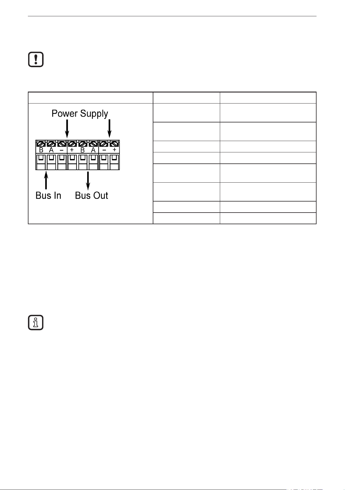
5.1 Connection of the signal and supply cables
Terminal Description
B (left) Signal cable B
A (left) Signal cable A
- 0 V
+ 10���30 V
B (right) Signal cable B
Incoming bus cable
Incoming bus cable
Outgoing bus cable
A (right) Signal cable A
Outgoing bus cable
- 0 V
+ 10���30 V
6 Installation
► Disconnect power�
► Ensure that the machine stands still�
► The drive must not be started during installation�
► Do not hit the shaft; do not use a file or similar tool on the shaft� Risk of
destruction!
This product is a precision measuring device� Therefore it has to be handled with care by trained
staff� The following warnings apply to influences outside the limit values indicated in the product data
sheet�
Damage to the product can be caused by:
● electrostatic discharge while touching the electronics
● too high forces on the shaft
● humidity and chemical liquids (do not connect any cables oriented upwards)
● extreme temperatures
● too high vibrations and shocks
● short circuit or too high an operating voltage
● impact, shock or any other physical forces
6
Page 7
Encoder with Profibus interface
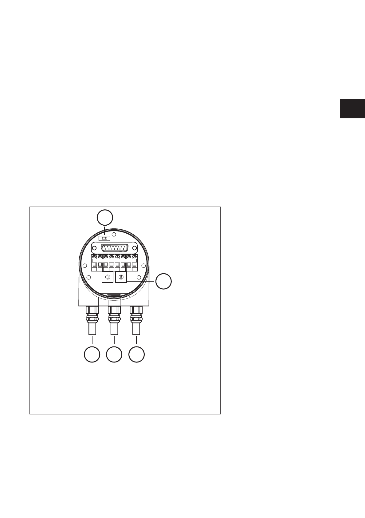
7 Installation
The encoder is connected via the terminal cap� It is connected to the encoder via
a 15-pole D-Sub-connector and can be removed by loosening the 2 screws on the
back of the device� Bus and supply cables are inserted in the cab via cable glands
and connected via screw terminals�
7.1 Settings in the terminal cap
7.1.1 Participant address
The Profibus participant address is set via decimal rotary switches in the terminal
cap� The positional value (x 10 or x 1) is indicated on the switch� Possible
addresses are between 1 and 99; each address must only occur in the system
once�
The device address is read when the voltage supply of the encoder is applied; a
change of address by the master [Set_Slave_Add] is not supported�
UK
Connection and setting of addressing
5
+-
BA
5
6
4
7
3
8
2
9
1
0
1
2
1: Supply +UB / - GND
2: Bus IN
3: Bus OUT
4: Addressing
5: Setting terminating resistor
BA
5
6
4
3
2
1
0
+-
7
8
9
4
3
7.1.2 Bus termination
If the encoder is installed as an end device, the terminal resistor integrated in the
device must be activated� This is done via the slide switch in the terminal cap (5)�
7
Page 8

Encoder with Profibus interface
When the terminal resistor is activated, the next bus (Bus Out) is decoupled�
The bus is only correctly connected if the encoder is installed on the terminal cap� If the encoder has
to be replaced during operation, the use of a separate active bus termination is recommended�
After the address has been set in the hardware and, if applicable, the terminating resistor has been
activated, the encoder can be put into operation�
8 Device configuration
Encoders with Profibus interface can be configured and parameterised according
to the requirements of the user�
In this respect the GSD file of the device is loaded into the projection tool� Various
encoder classes can be selected for the projection� Parameters and functionalities
of the device that can be set depend on the selected encoder class� ifm encoders
of the RM30xx and RN30xx series support all encoder classes described below�
Therefore the functionality is not restricted from the hardware side and is only
determined by the user� ifm encoders do not only provide the encoder classes
"Class 1" and "Class 2" described in the encoder profile but also encoder classes
with manufacturer-specific functions�
When configuring the device, configuration and parameter data are defined by
selecting the encoder class� This data saved in the Profibus master is transferred
once to the encoder when the system starts up (configuration and parameterising
phase – "DDLM_Set_Prm")� It is not possible to change configuration or
parameters during operation�
After the configuration and parameter data has been received, the encoder goes
into normal operation (cyclic data exchange – "DDLM_Data_Exchange mode")
in which, for example, the position value is transferred� The length and format of
the data exchanged are also defined when configuring the device by selecting the
appropriate encoder class�
9 Encoder classes
9.1 Class 1 and Class 2
The encoder classes Class 1 and Class 2 are the versions according to the
encoder profile defined by the encoder working group in the Profibus user
organisation (available from PNO indicating order no� 3�062)�
8
Page 9

Encoder with Profibus interface
9.2 Parameter setting
The following table gives an overview of the parameters that can be set according
to the encoder profile and of the arrangement in the parameter setting telegram�
Parameters are set using input masks in the projection tool�
Octet (= byte) no. Parameters Bit no. Details
1���8 Profibus standard parameters
9 Direction of rotation 0 → Chapter 9.2.1
Class 2 functionality 1 → Chapter 9.2.2
Commissioning diagnostics 2 → Chapter 9.2.3
Scaling function 3 → Chapter 9.2.4
Reserved 4
Reserved 5
Not used for Class 1 and Class 2 6
UK
7
10���13 Measuring steps / revolution → Chapter 9.2.5
14���17 Total resolution → Chapter 9.2.6
18���25 Reserved (to encoder profile)
26��� Not used for Class 1 and Class 2
Rotational direction
The direction of rotation defines the counting direction of the process actual value
output when the shaft rotates clockwise (CW) or counter-clockwise (CCW)� The
counting direction is defined by bit 0 in octet 9�
Octet 9 bit 0 Direction of rotation when viewing the shaft Direction of
rotation
0 Clockwise (CW) Rising
1 Counter-clockwise (CCW) Rising
9.2.1 Class 2 functionality
Class 2 encoders can be limited to the functionality of Class 1; the possibility of
parameter setting is disabled� To use the function of Class 2 encoders, bit 1 is set
in octet 9�
Octet 9 bit 1 Class 2 functionality
0 Disabled
1 Enabled
9.2.2 Commissioning diagnostics
This function is of no meaning for the ifm encoder�
9
Page 10

Encoder with Profibus interface
9.2.3 Scaling function
The scaling function enables parameter setting of the resolution per revolution and
the selected total resolution� It should always be enabled if you want to use the
functions of Class 2 (or the manufacturer-specific classes)�
Octet 9 bit 3 Scaling function
0 Disabled
1 Enabled
9.2.4 Measuring steps per revolution
This parameter is used to assign a requested number of steps referred to one
revolution to the encoder�
If the value of the parameter exceeds the actual physical basic resolution of the
encoder, the output value no longer proceeds by one step�
For encoders as of the B1 generation a parameter fault is displayed in this case;
the device does not change to the cyclic data transfer�
For high-resolution encoders it may be required to split the value into high word
and low word, depending on the projection tool�
Octet 10 11 12 13
Bit 31���24 23���16 15���8 7���0
Data 2
31
to 224 223 to 2
Requested number of measuring steps per revolution
16
215 to 2
8
27 to 2
0
9.2.5 Total resolution
Octet 14 15 16 17
Bit 31���24 23���16 15���8 7���0
Data 2
31
to 224 223 to 2
Selected total resolution in measuring steps
16
215 to 2
8
27 to 2
0
This parameter enables the user to adapt the measuring range of the device� The
encoder counts up to the configured total resolution and then it starts again at 0�
Example
Selected: 100 steps per revolution, total resolution 12800, then the encoder starts
again at zero after 128 revolutions and counts again up to 12799�
With many projection tools it may be required to split the value into high word and
low word�
10
Page 11

Encoder with Profibus interface
When the [Total measuring range] parameter is entered, use the following formula:
total resolution < measuring steps per revolution x number of revolutions
(physical)
If this is not observed, the device indicates a parameter fault and does not go into the cyclic data
exchange�
The internal software routine is only effective during operation�
9.3 Data exchange during normal operation
The DDLM_Data_Exchange mode is the normal status during system operation�
On request, the encoder sends current position values to the master� Conversely,
the encoder can also receive cyclic data (e�g� the preset value with Class 2
encoders)�
UK
9.3.1 Transfer of the process actual value
The current position value of the multiturn encoder is transferred as a 32-bit value
(double word) to the master�
Word Word 1 Word 0
Function Process actual value
Bit 31���30 29���16 15���0
0 X X
11
Page 12

Encoder with Profibus interface
9.3.2 Preset function
The preset function enables adaptation of the encoder zero point to the
mechanical zero point of the system�
► Set the encoder actual value to the requested preset value�
> The requested zero point drift is calculated by the device and stored in an
EEPROM (non-volatile) which takes less than 40 ms�
The preset value is activated in the peripheral output double word by setting bit
31 (adopted with rising edge)� Setting is made automatically after transfer of the
scaling parameters, i�e� the preset value refers to the scaled actual value�
Data bits
Bit 4 31 30 29...0
Master → encoder 1 0 Transfer of the requested value
(= preset value)
Encoder → master 0 0 New = requested process actual value is transferred
Master → encoder 0 0 Reset bit 31 - normal mode
Encoder → master 0 0 New = requested process actual value is transferred
Only set the preset while the encoder shaft is at standstill� If the shaft moves
during this time, shifts are possible since runtimes occur via the bus when the
preset value is set�
Note on the singleturn version
The process can be transferred to the singleturn version – here bit 15 is used to
activate the preset value� With high-resolution singleturn encoders (16 bits) no
preset values > 32767 (15 bits) can be set in Class 2 (MSB is used to activate the
preset value)� If this function is requested, one of the manufacturer-specific ifm
classes has to be selected (transfer here also in 32-bit format for the singleturn)�
12
Page 13

Encoder with Profibus interface
10 Profibus encoder profile Class 2
Parameter setting telegram
Octet (= byte) no. Parameters Bit no. Details
1���8 Profibus standard parameter
9 Direction of rotation 0 → Chapter 9.2.1
Class 2 functionality 1 → Chapter 9.2.2
Commissioning diagnostics 2 → Chapter 9.2.3
Scaling function 3 → Chapter 9.2.4
Reserved 4
Reserved 5
UK
Activate manufacturer-specific
parameters (octet 26)
Reserved 7
10���13 Measuring steps / revolution
(Reference: octet 26 bits 0 and 1)
14���17 Total resolution → Chapter 9.2.6
18���25 Reserved
26 Reference to the requested
measuring steps
Activate set-up mode 2 → Chapter 10.1.4
Reduced diagnosis 3 → Chapter 10.1.5
Reserved 4
Activate lower software limit switch 5 → Chapter 10.1.6
Activate upper software limit switch 6 → Chapter 10.1.6
Activate parameters as from octet
27
27���30 Lower limit switch → Chapter 10.1.6
6 → Chapter 10.1.1
→ Chapter 10.1.2
0
1
7 → Chapter 10.1.1
→ Chapter 10.1.3
31���34 Upper limit switch → Chapter 10.1.6
35���38 Physical measuring steps → Chapter 10.1.7
39 Reserved 0
Encoder (singleturn or multiturn) 1 → Chapter 10.1.8
Reserved 2
Reserved 3
Selection of the measuring unit to
provide the value of velocity
Reserved 6
Reserved 7
4
5
→ Chapter 10.1.9
13
Page 14

Encoder with Profibus interface
10.1 Parameters
The manufacturer-specific parameters are described below� The parameters to the
encoder profile (also supported) are described in chapter 9�
10.1.1 Activation of the manufacturer-specic parameters
The manufacturer-specific parameter byte 26 is activated via bit 6 in octet 9�
The manufacturer-specific bytes 27���39 are activated in byte 26�
Octet 9 bit 6 Octet 26
0 Deactivated
1 Activated
Octet 26 bit 7 Octet 27...29
0 Deactivated
1 Activated
10.1.2 Requested measuring steps
The device can be programmed with the [Desired measuring units] parameter so
that any number of measuring steps referred to
– one revolution
– the entire measuring range
– any part of the measuring range
can be implemented�
Octet 10 11 12 13
Bit 31���24 23���16 15���8 7���0
Data 2
31
to 224 223 to 2
Required number of measuring steps
16
215 to 2
8
27 to 2
0
14
Page 15

10.1.3 Required resolution
Parameter selection of
– resolution per revolution
– or max� total resolution
– code sequence
Encoder with Profibus interface
– Class 2 functionality
– scaling function
UK
Selection required resolution
Resolution per revolution
The position value is scaled so that it increases by the number of the required
measuring steps during one revolution�
In addition the [Total mesuring range] parameter is evaluated via which the
measuring range can be adapted (→ chapter 9.2.5)
Resolution per max� total resolution
The requested measuring steps entered refer to the total measuring range�
The device provides the configured number of measuring steps via the total
(physical) number of revolutions�
15
Page 16

Encoder with Profibus interface
Resolution per physical measuring steps
The requested number of steps refers to the data entered via the [Physical
impulses] parameter (→ chapter 10.1.7).
This is the numerical value that is read from the coded disc inside the encoder
(e�g� 4096 steps per revolution for the standard 12-bit version)�
This option allows free setting of gearbox factors�
Reference Octet 26 bit 0 Octet 26 bit 1
Per revolution 0 0
Per max� total resolution 1 0
Per physical measuring steps
(= steps indicated in octets 35-38)
0 1
10.1.4 Activate set-up mode
Bit 2 in octet 26 is a switch for the set-up mode�
In this mode other parameters besides the preset value can be transferred to the
encoder�
With activated mode a teach operation can be carried out; the gearbox factor can
be directly determined in the system�
In this mode (green LED flashing) the direction of rotation and scaling set during
projection are ignored and the values saved in the internal EEPROM are used�
The device can be operated permanently in the set-up mode�
Recommendation:
Transfer the parameters determined in the set-up mode and then use the device in
normal mode (which enables a replacement of the device without having to repeat
the teach operation)�
Octet 26 bit 2 Set-up mode
0 Off
1 On
16
Page 17

Encoder with Profibus interface
10.1.5 Reduced diagnosis
With older Profibus masters the full number of diagnostic bytes (standard
diagnosis: 57 bytes) may lead to problems� �
With the RM30xx and RN30xx devices it is possible to reduce the number of the
diagnostic bytes provided by the encoder to 16� If the device class "Class 1" is
selected, only 16 diagnostic bytes are provided in general�
Octet 26 bit 3 Diagnostic data length
0 Standard = 57 bytes
1 Reduced = 16 bytes
10.1.6 Software limit switch
UK
2 positions can be programmed� If they are exceeded or not reached, the encoder
sets bit 27 in the 31-bit process actual value to "1"�
Between the two positions the bit is set to "0"� Both limit switch values can be set
to any value via parameter setting but they must not exceed the value of the [Total
measuring range] parameter� The limit switches are activated via bit 5 or 6 in octet
26�
With many projection tools it may be required to split the values into high word and low word�
Octet 27 28 29 30 31 32 33 34
Bit 31���24 23���16 15���8 7���0 31���24 23���16 15���8 7���0
31
Data 2
���2
24
Octet 26 bit 5 Lower limit switch
0 Off
223���2
16
215���2
8
27���2
0
231���2
24
223���2
16
215���2
Lower limit switch in measuring steps (referred to scaled value)
8
27���2
0
1 On
Octet 26 bit 6 Upper limit switch
0 Off
1 On
17
Page 18

Encoder with Profibus interface
10.1.7 Physical measuring steps
Octet 35 36 37 38
Bit 31���24 23���16 15���8 7���0
31
Data 2
24
���2
Physical measuring steps
223���2
16
215���2
8
27���2
0
This parameter is evaluated by the device if the option [Physical impulses] was
selected as reference to the requested measuring steps� By means of the physical
measuring steps a gearbox factor can be freely set� Here it is defined how many
measuring steps (requested measuring steps) are to be provided on a defined
sub-measuring range� This option is useful if "odd" scaling factors are to be
entered�
Example
The encoder is to provide 400 steps over 3 revolutions�
With the reference [Desired measuring units per revolution] this number of steps
cannot be set (the [Desired measuring units] parameter should contain the value
133�333; however only integers can be entered)�
Remedy
The physical measuring steps are selected as reference for the requested
measuring steps�
The number of the physical measuring steps over the requested measuring range
is determined on the basis of the actual (physical) resolution of the device (type
label)� For this absolute encoder with 12-bit standard resolution this would in this
case be
4096 steps/revolution x 3 revolutions = 12288 steps
This value is now entered as [Physical impulses] parameter; the actually required
number of steps of 400 is entered at [Desired measuring units]� The encoder
now provides 400 steps over a measuring range of 12288 physical steps (i�e� 3
revolutions)�
Note: With many projection tools it may be required to split the value into high
word and low word�
10.1.8 Encoder type
The type of encoder (singleturn or multiturn) is defined in bit 1 of octet 39� This
is done automatically when the encoder class is selected� The user only has to
consider this parameter if parameters are set directly in the hexadecimal code�
Octet 39 bit 1 Type
0 Singleturn
1 Multiturn
18
Page 19

Encoder with Profibus interface
10.1.9 Unit of measurement velocity
The unit for the velocity value to be provided (class ifm 2�2) can be set via this
parameter�
Unit Bit 4 Bit 5
Steps / second 0 0
Steps / 100ms 1 0
Steps/10ms 0 1
Revolutions / minute 1 1
10.2 Data exchange during normal operation
The process actual value is in general transferred as a 32-bit word (double word)
with the manufacturer-specific encoder classes ifm 2�1 and ifm 2�2� In addition to
the 25 bits that are provided for the position value 7 other bits are used as status
bits� In the (peripheral) output double word the master sends the preset value and
in addition the control bits to the encoder�
For encoders of this type more than 25-bit absolute position data may be available�
The position values < 25 bits are not supported in the ifm classes; the more
significant bits are overwritten by status bits�
If the ifm classes are to be used with encoders whose physical resolution exceeds
25 bits, the user must ensure that the physical position value is scaled to a (max�)
output value < 33554432 (via parameter setting)� If absolute values > 25 bits are
required, Class 2 has to be selected�
UK
An additional (peripheral) input word of the current velocity value is transferred
with device class ifm 2�2�
Identification
Encoder →
master
Master →
encoder
F1 hex D0 hex
Status + position actual value Velocity
Status + 2
Preset value + control bits
Control + 2
24
24223
223 - 2
- 2
16
16
215 - 2
215 - 2
8
8
27 - 2
27 - 2
0
0
215 - 2
8
27 - 2
0
19
Page 20

Encoder with Profibus interface
The status bits in the input double word have the following meaning
Bit Meaning
28 Rotational direction 0 = increasing clockwise
(seen on the shaft)
27 Software
Limit switch
26 Operating mode 0 = set-up mode 1 = normal mode
25 Readiness for operation 0 = encoder not ready for
0 = lower limit switch ≤ actual
value ≤ upper limit switch
operation
1 = increasing counter-clockwise
(seen on the shaft)
1 = actual value > upper limit
switch or actual value < lower
limit switch
1 = encoder ready for operation
10.3 Set-up mode
If the encoder is switched to the set-up mode via parameter setting, the gearbox
factors can be determined directly in the system via a teach operation�
The set-up mode is signalled by the encoder via a flashing green LED in the
terminal cap and via bit 26 in the input double word (set to 0)�
In the set-up mode the parameters set during projection (direction of rotation,
scaling) are ignored and the values saved in the internal EEPROM are used� If the
direction of rotation and gearbox factor are changed during the set-up mode, the
new values are stored in the EEPROM�
Process during the set-up mode
► Install the device in the system�
► Enable the set-up mode via parameter setting�
► Adapt the direction of rotation (if required)�
► Move the system to the starting position�
► Transmit the start command for the teach operation to the encoder�
► Move the system to the end position�
► Transfer the requested number of steps to the encoder with the "stop teach
operation" command�
► Set the preset value�
► Transfer the values determined during the teach operation to the projection
(parameters)�
► Disable the set-up mode during parameter setting�
20
Page 21

Encoder with Profibus interface
10.3.1 Set the direction of rotation
The direction of rotation cannot be changed online in the set-up mode� The current
direction of rotation is displayed via bit 28 in the input double value (0: increasing/
1: decreasing clockwise)� The direction of rotation can be changed via bit 28 in the
output double word�
Status bits Data bits
Bit 31 30 29 28 27 26 25 24���1 0
UK
Master
→ encoder
Encoder
→ master
Master
→ encoder
Encoder
→ master
0 0 0 1 0 0 0 Select the direction of rotation
via bit 28
0 0 0 0/1 0 0 1 The encoder acknowledges the new
direction of rotation in bit 0 and bit 28
0 0 0 0 0 0 0 The selection is terminated by resetting
bit 28
0 0 0 0/1 X 0 1 Output of the process actual value
with changed direction of rotation
The set direction of rotation is saved in the EEPROM non-volatilely�
10.4 Start teach operation
► Move the system to the starting position�
► Transmit the start command for the teach operation to the encoder�
> The device starts the measurement to determine the gearbox factor internally�
0/1
Status bits Data bits
Bit 31 30 29 28 27 26 25 24���0
Master
→ encoder
Encoder
→ master
Master
→ encoder
Encoder
→ master
0 1 0 0 0 0 0 Start of the teach operation by setting bit 30
0 1 0 X X 0 1 Encoder acknowledges the start of the teach
operation by setting bit 30
0 0 0 0 0 0 0 Reset bit 30
0 1 0 X X 0 1 Output of the non-processed actual value
(gearbox factor = 1, preset not active)
10.4.1 Stop teach operation
► Transfer the requested number of steps to the encoder with the "stop teach
operation" command�
► Do not exceed the physical resolution (e�g� 20000 steps on a quarter of a
revolution)�
21
Page 22

Encoder with Profibus interface
Positive and negative direction of rotation and if the zero point is possible
exceeded is considered automatically� The measuring distance covered must not
be longer than half the measuring range of the encoder (i�e� max� 2047 revolutions
for the multiturn encoder with 4096 revolutions, max� 8191 revolutions for the 14bit multiturn)�
As response to the "stop teach operation" command the encoder transmits the
total resolution calculated by the device�
► Write down the value and accept it later for the normal operation of the system
in projection / parameter setting�
After this process the device works with the new scaling factor which is stored in
the EEPROM non-volatilely�
Status bits Data bits
Bit 31 30 29 28 27 26 25 24���0
Master
→ encoder
Encoder
→ master
Master
→ encoder
Encoder
→ master
0 0 1 0 0 0 0 Number of the requested steps over the
measuring range covered
0 1 1 X X 0 1 Transfer of the total resolution for the new
gearbox factor
0 0 0 0 0 0 0 Reset bit 29
0 1 0 X X 0 1 Output actual value (included in the new
gearbox factor)
Encoder replacement without a new teach operation
► Transfer the total resolution determined by the encoder to the projection�
Enter the total resolution determined during the teach operation into the parameter
field [Desired measuring units] (→ 10.1.2) and then set the switch to [Max. total
measuring range] → 10.1.3).
During the new configuration make sure that the direction of rotation is entered
correctly - the setting in the set-up mode must also be observed during parameter
setting� Then the set-up mode can be disabled via parameter setting; the encoder
is now used in "normal operation"�
22
Page 23

Encoder with Profibus interface
10.4.2 Preset value
The preset value is set according to the procedure described in chapter 9�3�2� Only
difference: Setting of the preset value with the manufacturer-specific classes ifm
2�1 and ifm 2�2 is confirmed via a status bit�
Status bits Data bits
Bit 31 30 29 28 27 26 25 24���0
Master
→ encoder
1 0 0 0 0 0 0 Tranfer of the requested value
(= preset value)
UK
Encoder
→ master
Master
→ encoder
Encoder
→ master
1 0 0 0 0 0 1 New = requested process actual value is
transferred
0 0 0 0 0 0 0 Reset bit 31 - normal mode
0 0 0 0 0 0 1 New = requested process actual value is
transferred
23
Page 24

Encoder with Profibus interface
11 Diagnostic messages
11.1 Overview
In the DDLM_Slave_Diag operating mode, diagnostic data is transferred from
the encoder to the master on request� The number of the diagnostic bytes is 57�
Exception: Reduced diagnosis� The diagnostic data is output according to the
definitions of the Profibus standard (octets 1-6) or according to the encoder profile
(starting with octet 7)�
Diagnostic function Data type Diagnosis
Octet number
Station status 1 (see: Profibus standard) Octet 1 1
Station status 2 (see: Profibus standard) Octet 2 1
Station status 3 (see: Profibus standard) Octet 3 1
Diagnostic master address Octet 4 1
PNO ID number Octet 5�6 1
Extended diagnostic header Octet string 7 1
Alarms Octet string 8 1
Operating status Octet string 9 1
Encoder type Octet string 10 1
Resolution per revolution (hardware) Unsigned 32 11���14 1
Number of revolutions (hardware) Unsigned 16 15�16 1
Other alarm messages Octet string 17 2
Supported alarms Octet string 18�19 2
Warnings Octet string 20�21 2
Encoder
class
Supported warnings Octet string 22, 23 2
Profile version Octet string 24, 25 2
Software version Octet string 26, 27 2
Operating time Unsigned 32 28���31 2
Zero point shift Unsigned 32 32���35 2
Manufacturer specific: Offset value Unsigned 32 36���39 2
Configured resolution per revolution Unsigned 32 40���43 2
Configured total resolution Unsigned 32 44���47 2
Serial number ASCII string 48���57 2
24
Page 25

Encoder with Profibus interface
11.2 Supported diagnostic messages
The individual diagnostic inputs are described in detail below�
11.2.1 Extended diagnostic header
Diagnostic byte 7 contains the length of the extended diagnosis (including the
diagnostic header)�
11.2.2 Memory error
UK
Via bit 4 in diagnostic by 8 it is indicated if a memory error has occurred�
In this case memory error means that the EEPROM of the encoder does no longer
function reliably and non-volatile storage (e�g� of the zero point shift) is no longer
ensured�
Bit Definition 0 1
4 Memory error
(Fault in
EEPROM)
No Ye s
11.2.3 Operating status
The operating parameters set via parameter setting can be enquired via diagnostic
byte 9�
Bit Definition 0 1
0 Rotational direction CW CCW
1 Class 2 functionality Off On
2 Diagnosis routine Off On
3 Scaling function Off On
11.2.4 Encoder type
The design of the encoder can be enquired via diagnostic byte 10�
Byte 10 Definition
0 Singleturn encoder
1 Multiturn encoder
11.2.5 Singleturn resolution
The physical resolution per revolution of the encoder is stored in the diagnostic
bytes 11���14�
25
Page 26

Encoder with Profibus interface
11.2.6 Number of revolutions
The physical number of the distinguishable revolutions per encoder can be
enquired via the two diagnostic bytes 15 and 16� The standard values for
singleturn is 1 and 4096 (or 16384) for multiturn�
11.2.7 Operating time alarm
The warning message for exceeding the operating time is indicated in bit 4 of
diagnostic byte 21� The bit is set after 105 hours�
11.2.8 Prole version
The profile version of the encoder is stored in the diagnostic bytes 24 and 25�
Bytes 24 25
Bit 15���8 7���0
7
Data 2
���2
0
27���2
0
Revision no� Index
11.2.9 Software version
The software version of the encoder is stored in the diagnostic bytes 26 and 27�
Octet 26 27
Bit 15���8 7���0
7
Data 2
Revision no� Index
���2
0
27���2
0
11.2.10 Operating time
The operating time of the device is recorded in the diagnostic bytes 28���31� While
the supply voltage is applied, the value (Operating time) is stored again in the
encoder in steps of 0�1 every 6 minutes�
11.2.11 Zero point shift
The zero point shift is provided in the diagnostic bytes 32���35�
11.2.12 Congured resolution
The configured resolution per revolution of the encoder is stored in the diagnostic
bytes 40���43� This value is only valid if the gearbox factor was calculated in the
parameter mask via the setting [Resolution per revolution]�
11.2.13 Congured total resolution
The configured or calculated total resolution is stored in diagnostic bytes 44���47�
26
Page 27

Encoder with Profibus interface
11.2.14 Serial number
According to the encoder profile, diagnostic bytes 48���57 are intended for a serial
number� At the moment the serial number is not stored in the device; the bytes are
pre-assigned with 2A hex�
12 LED indicators
12.1 Legend
LED on / lit The terminal cap has two LEDs that optically represent
LED flashes
LED off
Colour Status /
frequency
Red Green
Colour Status /
UK
the bus status on the encoder�
The red LED is used to display errors; the green LED to
display the status of the encoder� Each LED has three
states: off, on, flashing� Seven of the nine possible combinations are used to display a certain state�
Should there be problems during start-up of the device,
the status of the LEDs is to be checked; it often gives
information about the cause of the fault�
Description
frequency
No voltage supply
The encoder is operational but has not received any
configuration data after the voltage was applied�
Possible causes: Address incorrectly set; bus cables
incorrectly connected�
Parameter setting or configuration fault
The encoder receives configuration or parameter setting
data of an incorrect size or inconsistent data�
Possible cause: e�g� total resolution is set too high
The encoder is operational but is not addressed by the
master (e�g� incorrect address is addressed)�
The encoder does not receive any data for a longer
time (approx� 40 s) (e�g� data line interrupted)
Normal operation in the data exchange mode
Set-up in the data exchange mode
27
Page 28

Encoder with Profibus interface
13 Configuring with STEP7
In the following chapter the configuration of the ifm encoder with the configuration
tool Hardware manager STEP 7 is shown as an exemple�
In the example the STEP 7 version 5�4 SP4 and the CPU 315-2PN/DP are used�
13.1 Installation and import of the GSD file
Prior to initial configuration of the system in the hardware configurator of the
software, the GSD files of the encoder must be imported into the software�
Start the software and proceed as follows to import the above GSx files:
► Open new or existing project�
► Open hardware configurator
Copy the required GSx file via menu item [Options] → [Install GSD File...].
Importing a GSD file
The GSD file is supplied by ifm (free of charge on www�ifm�com)�
In order to display the encoder as a bitmap in STEP7 the file will be installed
automatically with the GSD file – both files must be in the same directory� The
main software release number in the GSD file and the firmware must be the same,
e�g� 4�xx�
► Select the GSD file from the according source directory�
28
Page 29

Encoder with Profibus interface
UK
Selecting the GSD file from the directory
After correct import and an update of the hardware catalogue via [Options]
→ [Update Catalog] the modules will be displayed as separate entries in the
hardware catalogue�
The exact configuration procedure can be found in the operating manual which is supplied together
with the software�
29
Page 30

Encoder with Profibus interface
13.2 Adding an encoder to a STEP7 project
To add an encoder to a project, the absolute encoder can be selected from the
hardware catalogue and added to the network� The requested device is coupled to
the bus by drag&drop (or double-click on the module with marked bus)�
When the device has been added, the participant address of the slave device is
entered� It must correspond with the address set in the terminal cap�
Adding an encoder to a STEP7 project
30
Page 31

Encoder with Profibus interface
13.3 Parameter setting
Mark the encoder to be configured in projection and then doubleclick on location
1 (table in the lower area of the station window)� The dialogue window [Properties
DP slave] appears� Here the default address of the device can be changed (if
requested)�
► Select [Parameter Assignment] in the tab to enter the parameters�
UK
Parameter setting of the encoder
31
 Loading...