

Page 1

System manual
ecomat 100 type R 360
Page 2

System manual ecomat 100 type R 360, April 1999
Guarantee
This manual was written with the utmost care. However, we cannot assume any guarantee for the
contents.
Since errors cannot be avoided despite all efforts we appreciate any comment.
We res erve the right to make technical alterations to the product which might result in a change of
contents of the manual.
page 2
Page 3

1. General 5
1.1. Safety instructions 5
1.2. Function and features 6
1.3. Controller configuration 7
1.4. Technical data 8
1.5. Mounting of the modules 12
1.6. Electrical connection of the modules 12
1.7. Fusing of the controller modules 12
2. The monitoring function 15
2.1. Hardware setup 15
2.2. Function of the monitoring concept 16
3. Unit I/O configuration 17
3.1. Bidirectional and diagnostic I/O channels 17
3.1.1. Bidirectional inputs/outputs 17
3.1.2. Outputs with diagnostic functions 18
3.2. Fast inputs 19
3.3. The software control configuration 19
3.4. Wiring 19
4. States and operating system 21
4.1. Operating modes 21
4.2. Status LED 22
4.3. Loading the operating sytem 22
4.3. Operating modes 25
5. Error codes and error classes 27
5.1. Reaction to system error 27
6. CAN in the ecomat R 360 29
6.1. Technical specifications 29
6.2. Exchange of data via CAN 29
6.3. CAN errors and error handling 31
6.4. The physical CAN link 33
6.5. General remarks on the CAN utilization 36
6.6. Description of the CAN function blocks 38
6.7. CANopen in the ecomat R 360 44
6.8. The ecomat R 360 as CANopen slave 48
6.9. The ecomat R 360 as CANopen master 59
6.10. Functions for CANopen I/O modules from ifm electronic 78
page 3
Page 4

7. PWM in the ecomat R 360 87
8. Fast counters in the ecomat R 360 97
9. Other functions in the ecomat R 360 101
9.1. Software reset 101
9.2. Save data in memory and read 102
9.3. Use of the serial interface 106
9.4. Reading the system time 110
9.5. Processing of variables 112
10. Closed-loop control functions 113
10.1. Adjustment rule for a controller 115
11. Functions of the ecomat tdm R 360 127
11.1. Data exchange and variable definition 129
11.2. Setting and resetting of pictures and messages 134
11.3. The unit status and the LEDs 137
11.4. Unit control 144
Annex 1. Address allocation ecomat R 360 147
Annex 1.1. Complete overview 147
Annex 1.2. Inputs 149
Annex 1.3. Outputs 150
Annex 1.4. Allocation outputs – short-circuit and wire-break bits 151
Annex 1.5. The flag range in the ecomat R 360 152
Annex 1.6. CANopen unit interface ecomat R 360 153
Annex 1.7. Object list of the ecomat R 360 154
Annex 1.7.1. Data range communication profile, index 1000 to 1FFF 154
Annex 1.7.2. Range of manufacturer-specific data, index 2000 to 5FFF 161
Annex 1.7.3. Legend to object library 161
Annex 2. Wiring 163
Annex 2.1. Type CR0015 163
Annex 2.2. Type CR0016 164
Annex 2.3. Type CR0017 165
Annex 2.4. Type CR0501 166
page 4
Page 5

1. General
1.1. Safety instructions
Observe the information of the description. Non-observance of
the notes, operation which is not in accordance with use as
prescribed below, wrong installation or handling can result in
serious harm concerning the safety of persons and plants.
The instructions are for authorised persons according to the
EMC and low voltage guidelines. The controllers must be
installed and comm iss ioned by a skilled elec tric ian ( progr ammer
or service technician).
This description is part of the unit. It contains texts and drawings
concerning the correct handling of the controller and must be
read before installation or use.
If the unit is not supplied by the mobile on-board system (24V
battery operation) it must be ensured that the external voltage is
generated and supplied according to the criteria f or safety extralow voltage (SELV) as this is supplied without further m easures
to the connected controller, the sensors, and the actuators.
The wiring of all signals in connection with the SELV circuit of
the unit must also com ply with the SELV criteria ( safe extr a-low
voltage, safe electrical separation from other electric circuits).
If the supplied SELV voltage as an external connection to
ground (SELV becomes PELV) the responsibility lies with the
user and the respective national regulations for installation m ust
be complied with. All statements in these operation instruc tions
refer to the unit the SELV voltage of which is not grounded.
The terminals m ay only be supplied with the signals indicated in
the technical data or on the unit label and only the approved
accessories of ifm electronic gmbh may be connected.
The unit can be operated within a wide temperature range
according to the technical specif ication indicated below. Due to
the additional self-heating the housing walls can have high
perceptible temperatures when touched in hot environments.
page 5
Page 6

In the case of malfunctions or uncertainties pleas e contact the
manufacturer. Tampering with the units can lead to
considerable risks for the safety of persons and plant. It is not
permitted and leads to the exclusion of any liability and warranty
claims.
1.2. Function and features
The controller modules ecomat 100 series R 360 (in the
following text ecomat R 360) are for the user under harsh
operating conditions (e.g. extended temperature range, strong
vibration, intensive EMC interference). T hey are thus suited for
direct mounting into machines in mobile and rugged
applications. Due to their specification the inputs and outputs
are especially rated for this use. Integrated hardware and
software functions (operating system) offer high protection of
the machine.
The controller ecomat R 360 is approved for safetyrelevant tasks in the field of safety of persons if the
corresponding system test routines are integrated in the
operating system and the application software. The final
classification and the release of the system (hardware an d
software) can only be done by the proper supervisory
organisations. The programmer has to obtain information
about the special characteristics of the hardware and
software in the additional documentation which can be
obtained on request.
ifm electronic gmbh
Teichstr. 4
D 45127 Essen
Tel.: 0201 / 2422-0
Fax: 0201 / 2422-303
The application software can easily be created by the user with
the ecolog 100
All software functions and programming processes
described in this documentatio n refer to the ecolog 100
plus
software.
plus
programming software the knowledge of which is required
for this description.
The user also has to obser ve the software versions (especially
the operating system of the R 360 and the function libraries) that
is used. Software levels are marked by suffixed letters in
alphabetic order in the file names ( e.g. CR0015_B.DL or TDMA.LIB). When revising existing application projects the user
should find out about incompatibilities between the old and the
new versions.
page 6
Page 7

The user is responsible for the safe functioning of the
application programs which he creates himself. If
necessary, he must additionally obtain an approval
according to the corresponding national regulations by the
relevant testing and supervisory organisations.
1.3. Controller configuration
The ecomat R 360 is a customer or application-specif ic conc ept
for series use which m eans that the control modules have the
optimum configuration to the application. If necessary, special
functions and special hardware solutions can be accomplished.
In general: All descriptions and explanations in t his manual
are generally applicable to the controller system ecomat R
360. The appropriate contro ller configuration f or the uni t in
use is to be loaded in the programming system (article
number of the unit, CRnnnn = file name controller
configuration CRnnnn_X).
Before using the controller modules you need to check the
availability of certain functions, hardware options, inputs and
outputs are available in the hardware.
page 7
Page 8

1.4. Technical data
Housing:
Housing dimensions:
Mounting position:
Connection of the unit:
Operating temperature:
Storage temperature:
Protection rating:
Protection class:
Air humidity:
Supply voltage:
closed, screened metal housing with flange fastening
225 x 153 x 43 mm (WxHxD), without connector
240 x 153 x 43 mm (WxHxD), with connector
preferably vertical, alternatively horizontal
55-pin connector, latched, protected against reverse polarity,
AMP pr Framatom type housing with crimp connection contacts
AMP junior timer 0.5/2.5 mm
2
-30°C ... +75°C
-40°C ... +90°C
IP67 (protection for connector, depending on cable version)
III
≤
90% rel. air humidity, non-condensing
U
nominal 12 or 24 V DC (-10% ... +25%)
B
See type label (reverse polarity protection through connector)
residual ripple:
≤
1.5 V
, f ≤ 50Hz
pp
Power consumption:
Processor:
Display:
Device monitoring:
Memory:
Interface:
reset in case of undervoltage 12 V unit:
reset in case of undervoltage 24 V unit:
overvoltage 12 V unit:
overvoltage 24 V unit:
≤
400 mA, without external load
≤
+ 9.6 V
≤
+12.0 V
≤
+ 17.5 V for t ≤ 10s
≤
+ 36.0 V for t ≤ 10s
CMOS microcontroller C 167C
two-colour-LED red/green for indication of status and error
8-bit microcontroller to m onitor the C 167C (extended watchdog
function)
check sum test for program and system
under and overvoltage monitoring, excess temperature
monitoring
256 kByte program memory
64 kByte data memory (volatile)
with 1 kByte data memory protected against voltage failure
(256 Byte auto-save)
CAN, Version 2.0 B (ISO/DIS-11898), 10 ... 1000 kBaud
protocol: CANopen or free communication profile
device class: CANopen master/slave; CAN: FullCAN
page 8
serial interface RS 232 C, 9,6 kBaud
number of participants: 2 (master/slave)
Page 9
Binary input
Low-Side (PNP):
Inputs IX0.0 ... IX0.7: switch-on level U
switch-off level U
≥ 10 V, I ≥ 3.3 mA
B
≤ 5 V, I ≤ 1.7 mA
B
input frequency 50 Hz
Inputs IX0.8 ... IX0.39: switch-on level 0.6 U
switch-off level 0.4 U
input frequency 50 Hz
Pulse inputs IX0.12 ... IX0.15: input frequency 50 kHz
Pulse inputs IX0.20 ... IX0.23: input frequency 50 kHz
Binary input
High-Side (NPN):
... 0.8 UB, I ≥ 6.7 mA
B
... 0.2 UB, I ≤ 1.7 mA
B
Inputs IX0.8 ... IX0.39: switch-on level 0.05 U
switch-off level 0.30 U
input frequency 50 Hz
Analog input
Low-Side:
Inputs IW9 ... IW16: input voltage +0 ... 10 V
input impedance
≥
50 k
resolution 10 Bit
accuracy
≤ ±
1.0 % FS
... 0.04 UB, I ≥ 7.7 mA
B
... 0.40 UB, I ≤ 5.1 mA
B
Ω
page 9
Page 10
Binary output
High-Side (PNP):
Outputs QX0.0 ... QX0.23: semiconductor output; short-circuit and overload protection,
diagnostic capability as an option
switching voltage 10 ... 17 V (12 V DC); 11 ... 32 V (24 V DC)
switching current 50 mA ... 2.5 A
overload current 5 A
sum current 10 A (per 8 outputs)
output frequency max. 100 Hz (depending on the load)
Outputs QX0.00 ... QX0.07 special specification as PWM output
output frequency max. 1000 Hz
PWM mark/space ratio 1 ... 99%
resolution depending on the PWM frequency
Binary output
Low-Side (NPN):
Outputs QX0.0 ... QX0.23: semiconductor output; short-circuit and overload protection,
diagnostic capability as an option
switching voltage 10 ... 17 V (12 V DC); 11 ... 32 V (24 V
DC)
switching current 50 mA ... 2.5 A
overload current 5 A
sum current 10 A (per 8 outputs)
output frequency max. 100 Hz (depending on the load)
page 10
Page 11

Input Test:
For the duration of the test operation (e.g. programming) the
connection needs to be connected to U
(supply).
B
For ”RUN” operation the input needs to be disconnected from
(supply).
U
B
Output Error (pin 13):
Relay output:
Housing drawing:
semiconductor output; short-circuit and overload protection
switching voltage 10 ... 17 V (12 V DC); 11 ... 32 V (24 V DC)
switching current 10 mA ... 100 mA
overload current 0.5 A
internal relay output
used in series with (max. 12 outputs the power supply of which
is interrupted on detection of an error by hardware or user
program
On principle, the unit should be switched load-free.
switching current 100 mA ... 15 A
overload current 20 A
no. of switching
operations (load-free)
response time
≥
≤
6
10
3 ms
page 11
Page 12

1.5. Mounting of the modules
In order to expose the controller modules to the minimum
mechanical stress they should preferably be mounted
horizontally or vertically on the mounting panel. The module
must be fixed with four scr ews to DIN 7500 or DIN 7984 (M5 x
L).
If possible, the modules s hould be mounted in such a way that
the cable entry of the plug points downwards.
1.6. Electrical connection of the modules
Before comm issioning it m ust be ens ured that the f ollowing pins
must/can be connected to the corresponding potentials.
Designation Pin No. Potential
Supply voltage 23 (VBBS) + 24 V DC
Ground 01 (GNDS) GND
Analog ground 12 (GNDA) GND
Supply voltage
outputs High-Side
without monitoring relay
Supply voltage
outputs High-Side
with monitoring relay
Supply voltage
outputs Low-Side
without monitoring relay
Test input,
programming mode
Test input, operating mode 24 (Test) open
Programming interface RS 232 06 (RxD) Pin 03, PC 9pin SUB-D
CAN interface 14 (CANH) CANH further participant
05 (VBBo) + 24 V DC
34 (VBB
15 (GNDo) GND
24 (Test) + 24 V DC
07 (TxD) Pin 02, PC 9pin SUB-D
33 (CM5) Pin 05, PC 9pin SUB-D
32 (CANL) CANL further participant
33 (CM5) GND further participant
) + 24 V DC
R
page 12
To guarantee the electrical interference protection of the
controller modules, the housings must be connected to
the ground of the vehicle.
1.7. Fusing of the controller modules
In order to protect the whole system (cabling and controller ) the
individual circuits must be fused accordingly, tak ing into ac c ount
the total current of 10 A of the individual output modules (max. 8
outputs – e.g. QX0.08 ... QX0.15).
Page 13

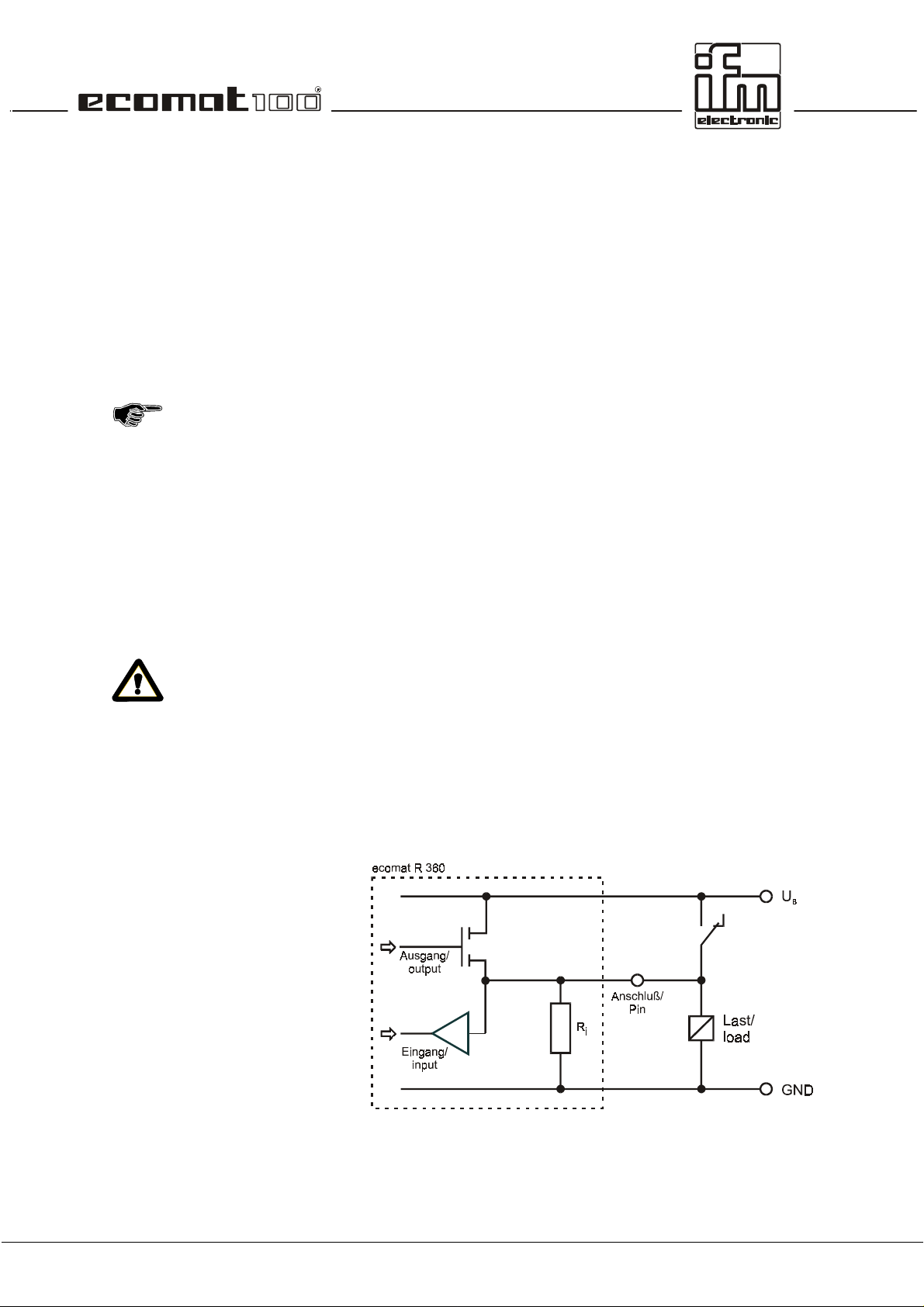
If an output terminal receives current externally, e.g. for
bidirectional inputs and outputs, the output rail must not
be floating (i.e. open-circuit)
Reason
The supply voltage is fed back to the output rail via the
integrated protective diode in the output. If a second output
connected to the same potential is switched, the load of this
output is fed through the transistor of the first output thus
causing the first output to overload and fail.
This needs special attention when unit and output voltage
supply are fused separately and when the output rail VBB
R
switched off by the software via the integrated relay. If
necessary, the supply voltage should be monitored via the
appropriate hardware and software measures.
is
page 13
Page 14

page 14
Page 15
2. The monitoring function
The safe operation of the controller outputs is ensured by the
monitoring function.
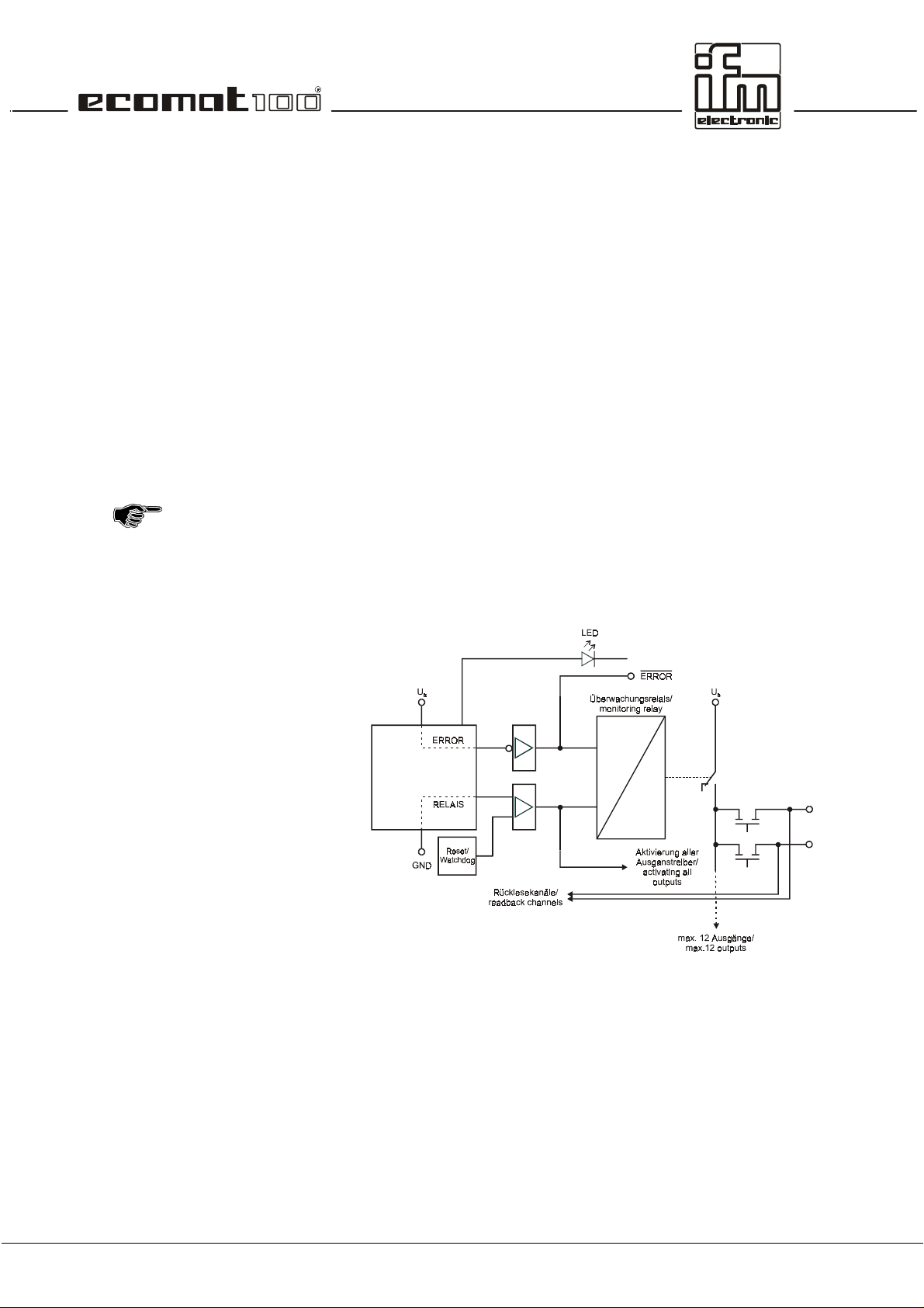
2.1. Hardware setup
The relay is triggered on two channels via the µcontroller. For
this purpose the negative channel is triggered by means of an
AND link of the watchdog signal (internal µcontroller m onitoring)
and the RELAY bit with a semiconductor switch. The positive
channel is only triggered by means of the ERROR bit via a
semiconductor switch. In the activated state the outputs to be
disconnected (max. 12) are connected to the supply voltage via
the relay contact (not forced)
In addition the output signal of the semiconductor switch has the
logical effect of a release signal for all outputs. These outputs
are only switched externally after the RELAY bit has been set.
Therefore the RELAY bit has to be set even if there is no
RELAY integrated in the hardware.
Schematic of the monitoring concept.
page 15
Page 16

2.2. Function of the monitoring concept
While the progr am is running the monitoring relay is under the
complete control of the software user. A parallel contact from
the safety circuit for example can be evaluated as an input and
the monitoring relay can be switched off. For further safety the
appropriate national regulations must be applied.
If a µcontroller error occurs while the program is running the
watchdog signal switches the relay off so that important par ts of
the plant can be protected.
When creating the program the programmer has to make
sure the program is left in a safe state (so that automatic
operation is reset) in the case of an internal (e.g. watchdog)
or external error (e.g safety circuit). For this purpose the
outputs in question have to be switched off by software.
If an output to be monitored is permanently switched and the
contact of the monitoring relay is welded it is not possible to
switch off this output. However, since the relay is always
switched load-free in normal operation, the contact wear is ver y
low.
page 16
Page 17
3. Unit I/O configuration
The unit I/O configurations des cribed in the annex are available
as standard units (ex stock). They cover the required
specifications for most of the applications.
Depending on the customer’s requirements for series
applications it is possible to realise other configurations, e.g.
regarding the arrangement of inputs and outputs and the design
of the analog channels.
The software functions described in this documentation only
apply to standard configurations. For customer-specific units
the specific hardware versions and additional software
description (additional documentation) have to be observed.
3.1. Bidirectional and diagnostic I/O channels
The inputs/outputs of the R 360 can be designed as
bidirectional input/output channels or for readback functions
(diagnosis, wire-break monitoring, short-circuit monitoring). At
the terminal the input and output or the output with the
corresponding readback c hannel (readback input) are available
simultaneously.
For safety-relevant applications outputs with readback
function (diagnostic outputs) are to be used.
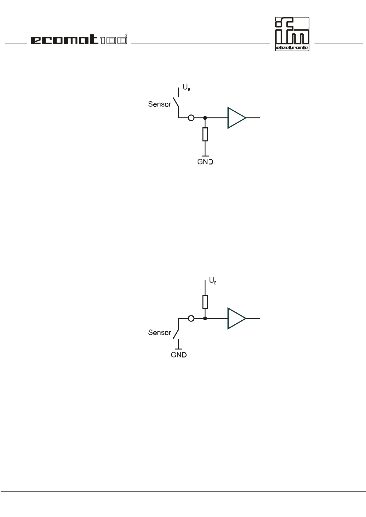
3.1.1. Bidirectional inputs/outputs
The connection can be used as an input or an output. The input
can be read via the software at any time.
page 17
Page 18
This function is based on the condition that in the controllers
high-side outputs are combined with low-side inputs or low-side
outputs are combined with high-side inputs so that no conf licts
can occur, i.e. short circuit via the switched output transistor and
closed switch at the input.
The block circuit diagram shows:
•
The load connected to the output can also be triggered
manually via the switch. The position of the switch can only
be detected when the output is blocked.
(Insert suppressor circuit via the load)
•
Short-circuit detection (overload) is also possible via the
input channel when the switch is open. The LOW (logic 0) is
read in when the output is switched.
In the case of a short circuit (overload) the output transistor
switches off automatically. For safety reasons it does not
switch on again automatically when the short circuit has been
removed. The output has to be switched off and then on
again via the software
•
Wire-break detection is not possible with this input/output
configuration.
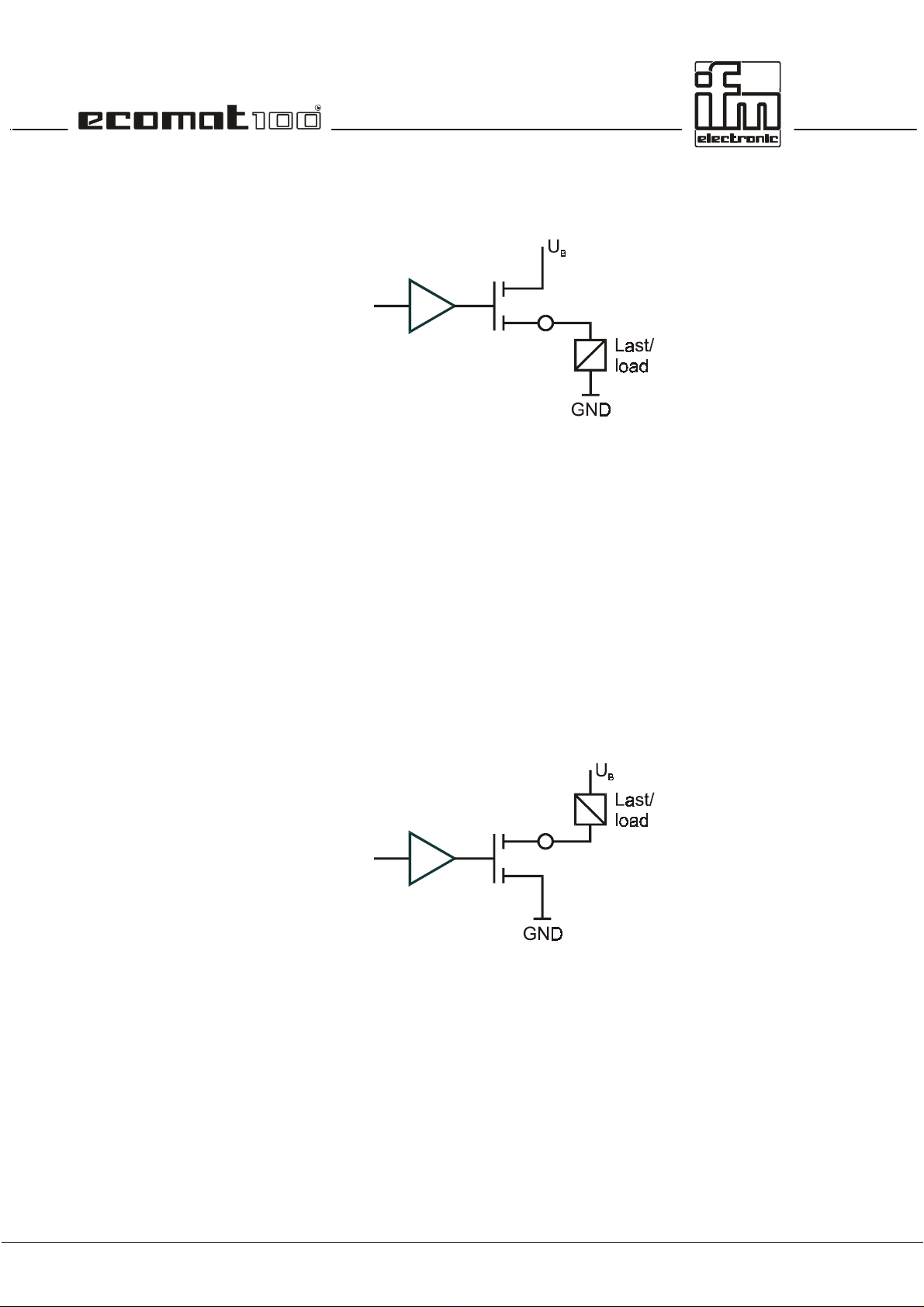
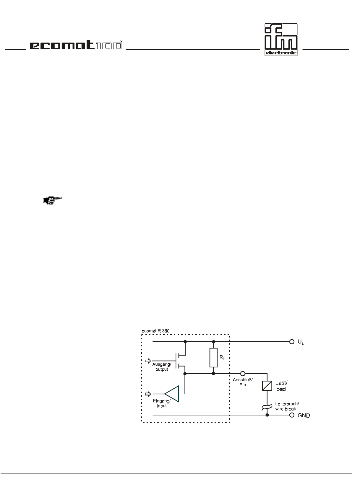
3.1.2. Outputs with diagnostic functions
The connection can be used as an input as well as an output.
The input can be read at any time via the software.
This function is based on the condition that in the controller
high-side outputs are combined with high-side inputs or low-s ide
outputs with low-side inputs.
page 18
Page 19

The block circuit diagram shows:
•
Short-circuit detection (overload) is possible via the input
channel. When the output is s witched the LOW (logic 0) can
be read in.
The output transistor automatically switches off in the case of
a short circuit/overload. For saf ety reasons it does not s witch
on again automatically. Therefore it has to be switched off
and then switched on again.
•
Wire- break detection is poss ible via the input channel. When
the output is blocked HIGH (logic 1) is read in as the resistor
pulls the output to HIGH potential (VBB). W ithout the wire
R
i
break the low-resistance load (R
< 10 k
L
Ω)
would force
(logic 0) LOW.
3.2. Fast inputs
In the controller modules the standard unit conf igurations have
an input frequency up to 50 kHz via 8 fast count/pulse inputs. If
e.g. mechanical switches are connected to these inputs , contact
bouncing might cause wrong signals in the controller. These
"error signals" have to be filtered out with the application
software, if required (see example program).
3.3. The software control configuration
For each hardware configuration the corresponding software
control configuration has to be loaded in the programming
system. For the programming system it repr esents the interfac e
to the hardware.
The software control configuration also provides the user with all
important system and error flags. Depending on the application
program they have to be processed and evaluated. They can be
accessed with their symbolic names or the IEC addresses.
3.4. Wiring
The wiring shown in the annex describes the standard unit
configurations. The wiring helps to assign the input and output
channels to the IEC 1131 addresses and the unit terminals.
page 19
Page 20

Labelling of the input/output channels:
12
GND
A
12 pin number
GND
A
pin description
30 %IX0.07 BL
30 pin number
%IX0.07 IEC address for a binary input
BL hardware design of the input
(here binary low-side)
47 %QX0.03 BH/PH
47 pin number
%QX0.03 IEC address for a binary output
BH/PH hardware design of the output
(here binary high-side or PWM high-side)
The abbreviations have the following meanings:
A analog input
BH binary input/output, high-side
BL binary input/output, low-side
PH PWM output, high-side
PL PWM output, low-side
IH pulse/counter input, high-side
IL pulse/counter input, low-side
R readback channel for an output
Allocation of the input/output channels:
Depending on the unit configuration an input and/or output is
available at a unit terminal.
Channels that can be used as inputs and outputs
simultaneously (bidirectional inputs/outputs) are highlighted
page 20
Page 21

Reset
Run
Stop
Fatal Error
No operating system
4. States and operating system
4.1. Operating modes
When the s upply voltage is applied, the controller module may
be in one of 5 possible operating modes:
This status is run through after each power-on reset. The
operating system is initialised. Diff erent checks ar e carried out.
This status is only temporary and is superseded by the run
status.
!"
The LED is lit red for a shor t time (is lit orange starting with
software version CRxxxx_G).
This status is reached:
•
from the reset status (Autostart)
•
from the stop status by means of the run command
prerequisite: test mode
•
with the CANopen NMT master via the function
PREOPERATIONAL or OPERATIONAL
!"
The LED flashes green or red (RUN with error)
This status is reached:
•
from the reset status if no program is loaded
•
from the run status by giving the stop command via the
interface
Prerequisite: test mode
•
with the CANopen NMT master via the function
PREPARED.
!"
The LED is constantly lit green or red (stop with error)
The controller passes into this status if a non-tolerable error is
found. This status can only be left via a reset.
!"
The LED is off (is lit red starting with software version
CRxxxx_G).
No operating system has been loaded, the controller is in the
bootloading status. Before loading the application software a
download of the operating system must be carried out.
!"
The LED flashes green (fast).
page 21
Page 22

4.2. Status LED
These operating states are shown with the integrated status
LED.
LED colour Flash frequency Description
LED off constantly off Fatal Error
green 5 Hz no operating system loaded
green 0.5 Hz Run, CANopen: PREOPERATIONAL
2.0 Hz Run, CANopen: OPERATIONAL
constantly on Stop, CANopen: PRERPARED
red 0.5 Hz Run w. error (CANopen: PREOPERATIONAL)
2.0 Hz Run w. error (CANopen: OPERATIONAL)
100 %
Reset checks or stop with error
The operating states STOP (PREPARED) and RUN (PREOPERATIONAL / OPERATIONAL) can be changed by the
programming system or the network master.
The user program is process ed in the RUN s tate. The controller
only takes part in the CANopen communication (PDO
processing, see chapter 6) when it is set to OPERATIO NAL. To
see the current operating state in the application program the
user can evaluate the flag COP_PREOPERATIONAL. The f lag
is TRUE when the state is PREOPERATIONAL, otherwise it is
FALSE.
4.3. Loading the operating sytem
When the unit is shipped an operating s ystem is in general not
loaded in the controller (LED flashes green at 5 Hz). In this
operating state only the boot loader is active. It provides the
minimum functions for the loading process of the operating
system (e.g. the support of the serial and the CAN interface).
In General, the download of the operating system only has to be
carried out once. The application program can then be loaded in
the controller (even several times). The advantage of this
process is that the EPROM does not need to be r eplaced for an
operating system update and that customer-specific operating
system can be realised for certain applications.
The operating system is provided together with this
documentation on a separate data carrier.
page 22
Page 23

Operating system download
New controller
Operating system update
The programmer has to ensure that the same so ftw are lev el
of the operating system (CR..._x.H86), of the controller
configuration (CR..._x.M66) and the unit library (CR..._x.LIB)
are used. If not, an error message is g enerated during the
download of the application software. Software states are
marked by suffixed letters in alphabetical order in the file
name (e.g. CR0015_B.H86). The basic file always has to be
the same.
The operating system and the application software are loaded
directly from the programming system. The download can be
carried out via the serial and via the CAN interface. The
following points have to be observed:
On delivery, the controller module does not contain an oper ating
system. When the supply voltage is applied it therefore goes
into the state "No operating system loaded". Only the bootloader
is active
!"
For downloading activate the controller configuration screen
via the button or via the menu item
Configuration.
!"
The requested controller configuration (CR..._x.M66) is
called via the menu item
!"
The connection between controller and PC can then be
established with
connection is made depends on the setting in
(serial or CAN) and the following param eterisation of
Config
the PC interface under
Parameters..
A communication connection to the controller is only
established when a project is loaded and when this is
translated without errors.
!"
The download process is started by select ing the m enu item
Extras / Load Hex file
screen
The new controller configuration file has to be used for all
application programs to be loaded in the controller.
In general, a new operating system software can be loaded in
the controller at a later time. T his process corresponds in most
parts to the one described above.
As opposed to the delivery sate of the controller, an operating
system is loaded, i.e. the controller is in the STOP or RUN
mode.
!"
The controller configuration of the operating system loaded
at current time is activated s o that the programming system
can establish the connection between controller and PC.
PLC Configuration
Online / Login
.
Insert / Firmware.
. The interface via which the
Online / Communication
and select file (CR..._x.H86) in the
.
Window / PLC
Extras / HW-
page 23
Page 24

!"
The controller configur ation sc r een is activated via the button
or via menu item
!"
The requested controller configuration (CR..._x.M66) is
called via menu item
!"
The connection between controller and PC is establis hed via
Online / Login.
connection depends on the setting in
(serial or CAN) and the subsequent param eterisation of the
PC interface under
It does not matter which project file is loaded (as long as
the project can be booted with routine PLC_PRG). The
translation processes started with the login can be
ignored. The system message:
Program has changed! Do you want to download the
Window / PLC Configuration.
Insert / Firmware
The serial interface for establishing the
Online / Communication Parameters..
.
Extras / HW Config
.
new program?
can be answered with NO.
!"
Menu item
Configuration
controller. The LED of the controller m odule flashes fast (5
Hz).
!"
Then reset the controller since the online connection
between PC and controller does no longer exist after the
operating system has been deleted.
!"
After the reset the new operating system can be loaded. T he
process is the same as for "New controller".
The new controller configuration file now has to be used f or all
application programs to be loaded in the controller from now on.
Extras / Load Hex file
deletes the current operating system in the
in the screen
PLC
page 24
Page 25

4.3. Operating modes
Independent of the operating states the controller can be
operated in different operating modes. The c ontrol bits can be
set and reset via the application software or in test operation
with the programming software ecolog 100
Variables
).
Test
To get this operating mode apply a high level (supply voltage) to
the test input. In the RUN or STOP mode the controller can now
accept commands via one of the interfaces. The state of the
user program can be queried via the flag TEST.
Serial Mode
The serial interface is available for a data exchange in the
application. Debugging of the application software is only
possible via the CAN interface.
This function is switched of f as a default (FALSE). T he state of
the user program or the progr amm ing system can be c ontrolled
and queried via the flag SERIAL_MODE.
ISO Direction
This function switches between Send data and Receive data
when the ISO 9141 interface is used..
TRUE Send data
FALSE Receive data (standard setting)
The flag ISO_DIRECTION is used to switch the ISO 9141
diagnostic interface between ´Send data´ and ´Receive data´.
The ISO interface is a special form of a serial interface that
provides communication with the diagnostic interfaces in the
vehicle.
The use of the ISO interface requires hardware and software
adaptations which are not included in the standard units.
When the ISO interface is used the serial interface is not
available for program download and debugging. Program
download and debugging are
interface
.
only
The function is only available when the test input is 'open'.
plus
(window:
possible via the
Global
CAN
page 25
Page 26

page 26
Page 27

5. Error codes and error classes
In order to ensure maxim um operational reliability the operating
system carries out internal error check s in the controller during
the start-up phase (reset phase) and during the program
execution.
The following error flags are set in the case of an error:
Error Error description
CAN_INIT_ERROR CAN module cannot be initialised
CAN_DATA_ERROR CAN inconsistent data
CAN_RX_OVERRUN_ERROR CAN overrun, received data
CAN_TX_OVERRUN_ERROR CAN overrun, transmission data
CAN_BUS_OFF_ERROR CAN not on the bus
CAN_ERROR CAN-Bus collective error bit
ERROR collective error bit (general)
ERROR_MEMORY memory error
ERROR_POWER under/overvoltage error
ERROR_TEMPERATURE excess temperature error (> 85°C)
COP_SYNCFAIL_ERROR SYNC object was not transferred
COP_GUARDFAIL_ERROR Guarding object is missing (only in the slave)
COP_GUARDFAIL_NODEID number of missing slave (only in the master)
5.1. Reaction to system error
It is the programmer's responsibility to react to error flags.
The specific err or bits should be proc essed in the user program
and then have to be reset. The error bit provides an error
description which can be further processed if required.
In the case of severe errors the ERRO R bit can be set causing
the operating LED to light red, the error output (pin 13) to be set
to LOW and the m onitoring relay (if there is one) to be switched
off. The protected outputs are de-energised.
The logic link via the relay bit ( see chapter 2) also sw itches
off all other outputs.
Depending on the application it has to be decided if the relay
and thus the outputs can be switched on again by resetting the
ERROR bit.
When using CAN for communication the function
CAN_ERRORHANDLER should be used. Thus all CAN errors
are detected as a collective error, are counted and CAN is
started again.
page 27
Page 28

Example
In addition, it is also possible to set the ERROR bit of "free
defined errors" via the user program.
In normal operation the relay should only be switched loadfree, so the function must o nly be used in an "emergency"
for a general switching-off of the outputs.
In order to reset all outputs in "normal operation" this function
should be accomplished via s uitable BIT links, not by using the
relay.
A CAN-BUS-OFF error occurs.
The operating system sets the CAN-BUS-OFF-ERROR bit.
The user program detects this state by polling the
corresponding bits.
If required the ERROR bit can be set:
As a result the operating display LED flashes red and the safety
relay is de-energised switching off all outputs. T he level of the
error output becomes low.
The error is removed by restarting CAN via the function call
CAN_RESTART. The CAN-BUS-OFF-ERROR bit is deleted
automatically.
If required the ERROR bit has to be deleted via the user
program. The relay energises again, the LED flashes green.
page 28
Page 29

6. CAN in the ecomat R 360
6.1. Technical specifications
Bus type: FULL-CAN
Physical layer: ISO/DIS 11898
Baud rate: 10 kBit/s ... 1 MBit/s
Protocol: CANopen
free protocol
2048 data objects in the system (CAN specification 2.0B)
Identifier use
System configuration
Only
The ecomat R360 is delivered with the device identifier 254 (ID
1 ... 2048 identifiers freely available for the data transfer
From these the following identifiers are reserved:
220 ... 221 reserved for the display tdm R 360
223 ... 252 device identifiers of the participants
254 device identifier of an unconfigured module
255 identifier of the download system (e.g. PC)
32) as participant 0. The download system uses this identifier
for the first communication with an unconfigured module.
one
unconfigured module may be connected with the
network. After the new participant number 1 ... 30 (corresponds
to the node identifier 1 ... 30) was assigned via the programming
software, a download or debugging can be performed and
another device can be integrated into the system (also see
section 6.5).
6.2. Exchange of data via CAN
The exchange of data via CAN is based on the internationally
standardized CAN protocol of the data link layer (level 2) of the
7-layer ISO/OSI reference model according to ISO 11898.
Each bus participant can send messages (multi-master
capability). The exchange of data operates sim ilar to r adio. Data
are sent to the bus without sender or address. The data are only
qualified by their identifier. It is the job of each participant to
receive the transmitted data and to check by means of the
identifier whether the data are relevant for this participant.
page 29
Page 30

This operation is automatically carried out by the CAN controller
in conjunction with the operating system. To avoid processing
each CAN message it is possible to only let a certain part of the
bus data reach the CAN controller by indicating a so-called
acceptance mask (CAN_ACCEPTANCE). The use of this
special function only makes sense if data are not relevant for
certain bus participants and time optim ization in a plc module is
absolutely required for CAN processing. To employ this function
hardware knowledge of the CAN controller is necessary. This
information is provided in the m anufacturer's documentation or
can be obtained from the technical support of ifm electronic
gmbh.
For the normal exchange of data via CAN the programm er only
has to inform the system of the data objec ts with their identif iers
by means of the functions CAN_RECEIVE and
CAN_TRANSMIT when designing the software. Via these
functions the RAM address of the oper ating data, the data type
and the selected identifier are combined to form a data object.
They then participate in the data exchange via the CAN bus.
The transmit and rec eive objects can be defined from all valid
IEC data types (e.g. BOOL, WORD, INT, ARRAY).
The CAN message consists of an identifier and max. 8 data
bytes. The identifier can be freely selected between 1 and 2048.
As already mentioned, it does not represent the sender or
receiver module but qualifies the message. To trans mit data it is
necessary that in the sender module a transmit object is
declared and a receiver object in
Both declarations must be assigned to the same identifier.
Receive data
Transmit data
The transmission order is rej ected if the controller is not ready
By calling the function CAN_TRANSMIT the application
In principle, the received data objects are automatically stored in
a buffer (i.e. without the user's influence).
A buffer (queue) is available f or each identifier. It is em ptied by
means of the function CAN_RECEIVE to the FIFO principle
(First In, First Out) depending on the application software. In the
queue
data transmissions can only be stored after the buffer has been
emptied. The reception of a new CAN message leads to
overflow of the queue, which is indicated to the user by the
OVERFLOW bit.
program transfers exactly one CAN message to the CAN
controller. As feedback you receive the inform ation whether the
message has been successfully transferred to the CAN
controller which then perform s the actual transfer of the data to
the CAN bus.
because it is in the process of transferring a data object. The
transmission order must then be repeated by the application
program. This inf o rmation is indicated to the user by m eans of a
bit.
max. 30
data transmissions are s tored tem porarily. More
at least one
other module.
page 30
Page 31

6.3. CAN errors and error handling
The error mechanisms described below are automatically
processed by the CAN controller integrated in the plc. This is not
influenced by the user. He must/should only react to errors
signalled in the application software.
Goal of the CAN error mechanisms:
•
Ensuring uniform data objects in the whole CAN network
•
Permanent function of the network also in case of a faulty
CAN participant
•
Distinction between temporary and permanent disturbance of
a CAN participant
•
Locating and automatic switch-off of a f aulty participant in 2
steps (error-passive, bus-off). This gives a temporarily
disturbed participant a "break".
To give the interested user an overview of the operating
characteristics of the CAN controller in case of an error, a
simple description of the error handling will be given below. After
the error detection the information is processed automatically
and is available to the programmer as CAN error bits in the
application software.
Error message
Error counters
However, in case of an error these error counters are
If a bus participant detects an error condition, it immediately
sends an error flag, thus causing the abort of the transm ission
or rejection of the correct messages already received by the
other participants. This ensures that all par tic ipants ar e provided
with correct and uniform data. Sinc e the er ror f lag is tr ansferr ed
immediately, the sender can immediately start to repeat the
disturbed message as opposed to other field bus systems
(which wait until a defined acknowledgement time has elapsed) .
This is one of the most important features of CAN.
One of the fundamental problems of the serial data transmission
is that a permanently disturbed or faulty bus participant can
block the whole system. This would be a danger especially for
the error handling method of CAN. To exclude this case, a
mechanism is required which detects a faulty participant and
switches it off from the bus, if necessary.
To do so, the CAN controller incor porates a transmission error
counter and a reception error counter. They are counted up
(incremented) for each erroneous trans m ission or r eception. If a
transmission was correct, these counters are counted down
again (decremented).
incremented more than they are decremented in case of no
error. During a certain time period this can lead to a s ubstantial
increase of the counts even if the number of undisturbed
messages is greater than the number of disturbed messages.
But longer time periods without errors reduce the c ounts again.
Thus the counts are a measure for the relative frequency of
disturbances.
page 31
Page 32

If a participant immediately detects an error it made (it is
responsible for the error), this participant is more severely
"punished" for the error than the other bus participants. To do
so, the counter is incremented by a higher amount. If the count
exceeds a certain value, it can be assu med that this par ticipant
is faulty. To prevent this participant from further disturbing the
bus communication by means of
active), it will become
error-passive
active error messages
.
(error-
Participant, error-active
Participant, error-passive
Participant, bus-off
The bus-off state can only be removed by a reset
An error-active participant takes part in the bus communication
without restriction and is allowed to signal detected errors by
sending the active error flag. As already described, this corr upts
the transferred message.
An error-passive participant is still capable of communicating
without restriction. But it is only allowed to signal an error it
detected by means of a passive error flag which does not
interfer with the bus operation. An error-passive participant
becomes again error-active if its count is again below a defined
value.
If the error count continues to increment, the participant is
switched off from the bus (bus-off) after a maximum count of
the participant has been exceeded.
(CAN_RESTART) of the CAN controller.
page 32
Page 33

But a detailed err or analysis can only be performed by means of
This is why the function CAN_ERRORHANDLER should be
used which registers all CAN error states and, if necessary,
resets the CAN controller. At the same tim e an error counter is
available to the application program. It could for example be
used to take further action depending on the c ount (e.g. error
LED).
an exact evaluation of the error bits.
6.4. The physical CAN link
The data transmission and error handling mechanisms
described in sections 6.2 and 6.3 are directly implemented in
the CAN controller. The physical link of the individual CAN
participants is described in layer 1 in ISO 11898.
Network structure
The standard ISO 11898 assumes a line-structured set-up of
the CAN network.
In addition, the line must be fitted with a terminating
resistor of 120
electronic's devices fitted with a CAN interface have no
terminating resistors.
Ideally, no spur should lead to the bus participants (node 1 ...
node n) because depending on the total cable length and the
transmission time reflections occur in the bus. To avoid this
leading to system errors, the spurs to a bus partic ipant (e.g. I/O
module) should not exceed a certain length. 2 m spurs are
considered to pose no problem. The sum of all spurs in the
whole system should not exceed 30 m. In special cases the
cable lengths of the line and the spurs must be accurately
calculated.
ΩΩΩΩ
at its two ends. In principle, ifm
page 33
Page 34

Bus level
l
Bus cable length
The CAN bus is in the inactive (recessive) state if the output
transistor pairs are switched of f in all bus par ticipants. If at leas t
one transistor pair is switched on, a bit is s ent to the bus which
then becomes active (dom inant). Thus a current flows through
the terminating resistors and generates a different voltage
between the two bus cables. The recessive and dominant states
are converted into corresponding voltages in the bus nodes and
are detected by the receiver circuits.
This differential transmission with a common return line
considerably improves the transmission safety. Interfering
voltages which affect the system externally or mass potential
offsets influence both signal lines with the same interfering
quantities. They are therefore ignored when the difference is
formed.
The bus cable length depends on the c haracteristics of the bus
connection (cable, connector), the cable resistance and the
necessary transmission rate (baud rate). As described above,
the length of the spurs mus t also be considered for the network
design. For the sake of simplicity, the following dependence
between bus length and baud rate can be assumed.
page 34
Page 35

Wire cross-sections
For the design of the CAN network the wire cross-s ection of the
bus cable used must be tak en into account. The following table
describes the dependence of the wire cross-sections on the
number of the bus participants refer red to a transmission rate of
1 Mbit/s and a maximum cable length of 40 m (cable r esistance
r = 70 mΩ/m).
Cable length 32 bus nodes 64 bus nodes 100 bus nodes
100 m
250 m
500 m
0.25 mm2 0.25 mm2 0.25 mm2
0.34 mm2 0.50 mm2 0.50 mm2
0.75 mm2 0.75 mm2 1.00 mm2
Depending on the EMC requirements the bus cables can be laid
in parallel or as a twisted pair with or without screen.
page 35
Page 36

6.5. General remarks on the CAN utilization
If in connection with the plc ecomat R 360 CAN or CANopen is
used, some points must be taken into account. They concern
the physical structure of the CAN network and the correct
software handling.
Physical network structure
Software for CAN and CANopen
The following points must be considered:
The following applies to the CAN network structure:
•
Ensure that the selected data transmiss ion rate is not higher
than needed. A low transmission rate increases the
operational reliability.
•
The cable length must match the data tr ansm ission rate. For
R 360 it is typically 400 m at 125 kBaud.
•
Lay the bus cable in a line and avoid spurs. Ensure clean
and firm terminal locations to avoid unnecessary contact
resistance. If necessar y, lay the cables as a twisted pair with
or without a screen.
•
Fit both ends of the bus cable with a terminating resistor of
120 Ω.
•
The higher the number of the partic ipants in the network , the
more carefully the network m ust be laid out (cable version,
cable length, etc.).
In principle, R 360 can directly take part in the CAN
communication (layer 2) by using the functions
CAN_TRANSMIT and CAN_RECEIVE. In the CANopen mode
the programmer is supplied with the defined services.
•
In the direct CAN mode in layer 2 the programmer is
responsible for all services. The plc is in this state after a
program download or a reset com mand by the programm ing
system.
•
For the direct CAN mode the cyclical integration of the
function block CAN_ERRORHANDLER is recommended.
Otherwise, the application program must perform a
CAN_RESTART in the case of BUS_OFF.
•
After a program download or a reset command by the
programming system the plc is not yet a CANopen device.
To change to the CANopen mode the flag CAN_OPEN mus t
be set at the start of the program. The R 360 then operates
as a CANopen slave.
•
If a R 360 slave is stopped via the pr ogramming sof tware, a
following node start command of the CANopen master is
ignored. However, a stop command of the master
(NMM_SET_PREPARED) is always executed.
page 36
Page 37

•
In case of a missing guarding reply of the R 360 slave the
master continuously sends node resets. This can lead to
problems when logging on the program ming system via the
CAN interface. In this case the master must be switched
off.If the R 360 is also to operate as a CANopen master , it
must be initialized with the function
NMM_SET_NMT_MASTER.
If the plc is stopped (via PC), it retains the CANopen
functions, but the master functions are interrupted (e.g. no
SYNC message).
•
All participants of the CAN network m ust be clearly assigned
a module ID.
Device IDs in the ecomat R 360
To communic ate with the participants in the CAN network each
must have a defined device identifier. It is of no importance
whether the plc is used as network mast er, as CANopen slave
or for the direct CAN com munication. Make also sure that the
device identifiers do not overlap with the IDs of the I/O modules.
The ecomat R 360 is supplied with the default ID 32 (under
CANopen). In the programming software ecolog 100
plus
the
node ID 32 is designated as the module ID no. 0.
Module ID
ecolog 100
plus
Node ID
CANopen
Device ID
debugger
(default) 0 (unconf.) 32 0xFE
1 1 0xDF
2 2 0xE0
3 3 0xE1
: : :
29 29 0xFB
30 30 0cFC
The device ID can be assigned online via ecolog 100
plus
.
page 37
Page 38

6.6. Description of the CAN function blocks
The CAN function block s for use in the application program will
be described below.
To utilize the full functions of CAN it is absolutely required for
To be able to set up a communication link the same
Example program
the programmer to create a precise bus c oncept before starting
to work. The number of the data objects with their identifiers
must be defined as well as a reaction to possible CAN errors.
Also, the frequency with which data must be transm itted has to
be taken into account. So the functions CAN_TRANSMIT and
CAN_RECEIVE must be called just as frequently. The
programmer must additionally monitor whether his transmission
orders have been passed on succ essfully to CAN_TRANSMIT
(bit RESULT) or must make sure that the data received are read
from the data buff er of the queue with CAN_RECEIVE and are
immediately processed in the program.
transmission rate (baud rate) must first be s et f or all partic ipants
of the CAN network. For the R 360 this is done with the function
CAN_BAUDRATE.
An example program in function block diagram (FBD) is stored
on the program diskette ec olog 100
plus
(CAN 3_66.PRO). In this
example data objects are exchanged with another CAN
participant via the identifiers 1 and 2. To do so, the other
participant must have a receive identifier for the transmit
identifier (or vice versa).
The function CAN_ACCEPTANCE is not f urther descr ibed here
because the application requires thorough hardware knowledge
of the CAN controller. Users who need this spec ial feature are
requested to contact the technical support.
page 38
Page 39

Function
Library CRxxxx.LIB
Function symbol
Purpose
Parameters
Function outputs, none
Description
CAN_BAUDRATE
Sets the transmission rate for the bus participant.
Function inputs
Name Data type Description
ENABLE BOOL TRUE: The function is processed.
BAUDRATE WORD Value of the baud rate to be set in kBit/s
With the func tion CAN_BAUDRATE the transm ission rate is set
for the plc module. To do so, the corresponding value in kBit/s is
indicated at the function input BAUDRATE. After the exec ution
of the function this new value is stored in the device and is also
available again after a power failure. The factory default for the
baud rate of the modules is 125 kBit/s.
The function should be executed only once during the
initialization in the first program cycle. After that it is disabled via
the input ENABLE.
The baud rate becomes immediately valid after the function call.
FALSE: The funct i o n i s n o t p r o c e s s e d .
(10, 20, 50, 100, 125, 250, 500, 1000 )
page 39
Page 40

Function
Library CRxxxx.LIB
Function symbol
Purpose
Parameters
Function outputs
Description
CAN_TRANSMIT
Passes a CAN data object (message) on to the CAN c ontroller
for transmission.
Function inputs
Name Data type Description
ID WORD Contains the number of the data object
RTR BYTE Not used, therefore value 0
DLC BYTE Number of the bytes to be transmitted from
DATA ARRAY The array contains max. 8 data bytes.
ENABLE BOOL TRUE: The function is processed.
Name Data type Description
RESULT BOOL TRUE: The function has accepted the
CAN_TRANSMIT is called f or each data object in the program
cycle, for long program cycles sever al times. The program mer
must ensure by evaluating the bit RESULT that his transmiss ion
order has been accepted. It can be said that for 125 kBit/s one
transmission order can be executed every 1 ms.
Via the bit input ENABLE the execution of the function can be
disabled temporarily. This can for example prevent a bus
overload. Also, several data objects can be sent quasi
simultaneously if each data object is assigned a flag used to
control the execution of the function via the ENABLE input.
identifier 0 ... 2048.
the array DATA (permitted values 0 ... 8).
FALSE: The function is not processed.
transmission order.
page 40
Page 41

Function
Library CRxxxx.LIB
Function symbol
Purpose
CAN_RECEIVE
Configures a data reception object and reads the reception
buffer of the data object.
Parameters
Function outputs
Description
Function inputs
Name Data type Description
CONFIG BOOL For the configuration of the data object the
CLEAR BOOL Deletes the data buffer (queue).
ID WORD Contains the number of the data object
Name Data type Description
DATA ARRAY The array contains max. 8 data bytes.
DLC BYTE The number of the transmitted bytes in
RTR BYTE Is not used
AVAILABLE BYTE Number of the messages received
OVERFLOW BOOL TRUE: Overflow of the data buffer.
CAN_RECEIVE must be called once for eac h data objec t dur ing
the initialization phase to inform the CAN controller of the
identifiers of the data objects.
In the further program cycles CAN_RECEIVE is called to read
the corresponding reception buff er, for long program cycles this
is done several times. The programmer must make sure by
evaluating the byte AVAILABLE that newly received data objects
are retrieved from the buffer and are further processed. Each
call of the function decrem ents the byte AVAILABLE by 1. If the
value of AVAILABLE equals 0, the buffer contains no data.
By evaluating the bit OVERFLOW an overflowing data buffer
can be detected. If the bit OVERFLOW is set, at least 1 data
object is
lost
.
bit must be set TRUE once. For data
transmission to commence the CONFIG bit
must be set to FALSE.
identifier 0 ... 2048.
the array DATA, possible values 0 ... 8.
Data loss!
FALSE: The buffer is not yet full.
page 41
Page 42

Function
Library CRxxxx.LIB
Function symbol
CAN_RESTART
Purpose
Parameters
Description
Restart of the CAN participant after "serious" transmission
errors (bus-off state).
Function inputs
Name Data type Description
ENABLE BOOL TRUE: The function is processed.
FALSE: The function is not processed.
Function outputs, none
CAN enables a distinction between a temporary and a permanent disturbance of a bus partic ipant. As desc r ibed in sec tion
6.3, three function states are available.
If a participant is
If a certain number of trans mission errors occ urs , the partic ipant
becomes
participant becomes again
If a participant is already error-passive and transm ission errors
continue to occur, it is switched off from the bus (
the error flag CAN_BUS_OFF_ERROR is set. A return to the
bus is only possible with the function CAN_RESTART. The error
flag is reset after a successful return.
The input ENABLE suppresses the execution of the function.
error-passive
error-active,
. If the error frequency is r educed, the
error-active
this is the normal state.
.
bus-off
) and
page 42
Page 43

Function
Library CRxxxx.LIB
Function symbol
CAN_ERRORHANDLER
Purpose
Parameters
Function outputs
Description
The programmer's job is to locate the precise error cause by
Minimum error routine to monitor CAN.
Function inputs
Name Data type Description
RESET BOOL Deletes the error counter.
Name Data type Description
ERRORCOUNT
CAN_ERRORCOUNT evaluates all possible CAN errors and
totals the number of the errors in the c ounter ERRORCOUNT.
In the case of a bus-off error the function tries to return the
participant to the bus. To do so, the function CAN_RESTART is
integrated.
evaluating the error counter and the error bits supplied by the
system. Via the function input RESET the counter can then be
set to 0 again.
In each application software where the CAN com munication is
utilized (also for the communication with a CAN display) at
least this function should be employed and processed
cyclically.
WORD Error counter, contains the number of the
errors occurred.
page 43
Page 44

6.7. CANopen in the ecomat R 360
The CAN layers 1 and 2 described at the beginning of chapter 6
control the physical link and the transmission of the data
between the bus participants. For a practical CAN application
this means that the program mer is responsible for the definition
of the data protocol for the special application.
To obtain a uniform protocol layer for networking the different
participants which describes the meaning of the transmitted
data the CAN Application Layer (CAL) was determined as layer
7. CANopen is based on CAL and defines which data are to be
transmitted by which CAL services. The meaning of the data f or
the corresponding device type (I/O module, drives, encoders,
etc.) is also defined. With these definitions the application
programmer can access all components with CANopen
capability independent of the manufacturer and without much
work on the protocol. CANopen participants which belong to the
same device family have organized their data the same way.
The characteristics of these device clas ses are indicated in the
"device profiles" (DS-40x).
Despite this definition the basic CAN structure which allows
each bus participant to send mess ages (data) to the network is
maintained. Only the network master ( NMT m aster) exists once
and is mainly used for running up and monitoring the system.
The mechanism s described below are to give a rough overview
of the CANopen functions. If you wish to utilise the full CANopen
functions, please contact CAN in Automation Technical Centre.
General information on CANopen
The object-oriented identifiers (11 bits) ar e called "CAN Object
In principle, each CANopen node has an object directory which
can be accessed via "Service Data Objects" (SDOs). In
addition, there are at least two "Process Data Objects" (PDOs)
for transmitting and rec eiving process data, a "Node Guarding
Object" to monitor the network as well as an "Emergency
Object" to indicate error states.
Ids" (COB IDs) under CANopen. Via the 4 most significant bits
(MSBs) they are divided into 16 groups. The rem aining 7 bits
are used to distinguish 127 CANopen nodes. This ensures a
clear assignment of the individual object types to the nodes.
This definition is a default assignment.
page 44
Page 45

The object directory
Service Data Object (SDO)
It is defined in the "predefined connection set”. Whether this
default is adhered to or not depends on the corresponding
application. To ensure a high flexibility as regards the selection
of CANopen devices from different manufacturers you should
carefully consider whether non-adherence is required.
Object Code
(binary)
NMT 0000 0000000 0 Network managem.
SYNC 0001 0000000 128 Synchronization
EMCY 0001 xxxxxxx 129 - 255 Error states
TIME STAMP 0010 0000000 256 Network time
PDO1(tx) 0011 xxxxxxx 385 - 511 Synchronous PDO
PDO1(rx) 0100 xxxxxxx 513 - 639 Synchronous PDO
PDO2(tx) 0101 xxxxxxx 641 - 767 Asynchronous PDO
PDO2(rx) 0110 xxxxxxx 769 - 895 Asynchronous PDO
SDO(tx) 1011 xxxxxxx 1409 - 1535 Master->slave SDO
SDO(rx) 1100 xxxxxxx 1537 - 1663 Slave->master SDO
Nodeguarding 1110 xxxxxxx 1793 - 1919 Node/life guarding
All node parameters are stored in the object directory of the
corresponding CANopen node. To ensure a clear identification a
directory entry is marked by an index (IDX, length 16 bits) and a
subindex (SUBIDX, length 8 bits). Depending on the param eter
type they are stored in the individual index areas. The m eaning
of the individual indexes for the communication and standard
parameters are defined for the individual device types in the
CANopen standard. In addition, an area for manufacturerspecific data is available. In this area the configuration
parameters for the I/O modules f rom ifm elec tronic gmbh are for
example stored.
Index (hex) Object
0000 Not used
0001 - 009F Data types
00A0 - 0FFF Reserved
1000 - 1FFF Area for the communication profile
2000 - 5FFF Area for the manufacturer-specific data
6000 - 9FFF Area for standard device parameters
A000 - FFFF Area for gen. IEC1131 network variables
A read and write access to the object director y is achieved via
the "Service Data Objects" (SDOs).
The SDOs are used for all data in CANopen which are not time
critical. In principle, they are only transmitted from point to point
(network master / s lave). The SDO s are c hiefly used to transm it
the configuration data of the CAN participant during the booting
phase.
COB IDs
(decimal)
Default function
page 45
Page 46

Process Data Object (PDO)
Node Guarding Object
Emergency Object
In the object direct ory of the node these err ors are s tor ed. T o do
The time critical process data are transferred by means of the
"Process Data Objects" (PDOs). T he PDOs can be exchanged
between the individual nodes in any way (PDO linking). It is also
defined whether the data exchange is event-controlled
(asynchronous) or synchronized. Depending on the type of data
to be transferred the right choice of the transmission type can
considerably relieve the amount of data transm itted on the CAN
bus. The default setting of the I/O modules from ifm electronic
gmbh specifies a synchronous transmission of analog input data
and all output data and an event-controlled transmission of
digital input data.
To detect communic ation errors in the network node guarding is
used. Each bus node is cyclically accessed by the network
master via the defined node guarding COB ID. If no reply is
given within the defined guard time, the m ast er s ignals an error .
Via the life time (life time factor * guard time) it can also be
defined after how many unsuccessful attempts the error
message is to be created.
If an internal error occurs in a bus participant (e.g. wrong
configuration parameter, short circuit at the output) an EMCY
object is created. This EMCY object is standardized and is sent
once when the error occurs and once when the error state has
disappeared.
so, the "error register", the "manufacturer-specific status
register" and the "error history" are available.
page 46
Page 47

Boot-up routine
During the boot-up routine the network master allows the
network to run up. In this process the m aster is infor med of the
most important communication parameters and, if necessary,
guarding is activated. During the boot-up routine the
configuration parameters s hould also be transferred. The node
should be in the "pre-operational" state.
State Description
6 Start remote node indication
7 Stop remote node indication
8 Enter pre-operational state indication
10 Reset node indication
11 Reset communication indication
12 Initialization finished - enter pre-operational automatically
To ensure a successful boot-up routine at least the node
number and baud rate of the CAN participant m ust be set. The
baud rate of the master must conform to this. This setting is
done via DIP switches in the node or an additional parameter
setting software. Since the plc R 360 also allows a description of
the object directory via the SDOs, setting can also be done via
the plc.
To ensure that the ecomat R 360 operat es in the CANopen
mode the flag CAN_OPEN must be set to TRUE at the
program start (during the initialization).
page 47
Page 48

Object directory
Baud rate and node number
6.8. The ecomat R 360 as CANopen slave
The ecomat R 360 can also be used as a programmable
input/output module under CANopen. It behaves like a
CANopen slave. As CANopen slave the ecomat R 360 is
classified as a "programmable device" according to CiA DS 405.
To use the R 360 as CANopen slave the system bit CAN_OPEN
must be set.
The device parameters can be accessed via the object
directory. If they are identified as read/write, they can be
changed via SDO_WRITE and by the NMT master or by an
external parameter setting system.
The object directory in the ecomat R 360 has three m ain areas.
The CANopen communication parameters are stored as from
index 1000 hex.
As from index 2000 hex the manufacturer-specific data of baud
rate and node number are stored.
As from index A000 hex starts the area for the general IEC1131
network variables. They are transferred via the PDOs. The
identifiers and the transmis sion types of the PDOs are entered
in this area.
For the exact structure of the object directory see point 1.6 in
the appendix.
The baud rate and node number are entered in the
manufacturer-specific area of the object directory from index
20F0 / 20F1 hex and 20F2 / 20F3 hex. The baud rate or node
number can be changed via a SDO by the master, a function
call or the programming system. If the change is made via
SDO_WR ITE, both entries in the obj ect directory m ust have the
same contents. The change of the baud rate only becomes valid
after a reset, that of the node ID at once.
Index Subindex Name Default value
20F0 0 Node ID 32
20F1 0 Node ID 32
20F2 0 Baud rate 3
20F3 0 Baud rate 3
On no account are two participants with the same node
number allowed in the network.
page 48
Page 49

Retentive data
PDOs
For setting the baud rate the following parameters are allowed:
Number Baud rate (kBit/s)
0 1000
1 500
2 250
3 125
4 100
5 50
6 20
7 10
Via the manufacturer-specific area of the object directory it is
possible to transfer a max. 256-byte data block to the R 360
slave by means of SDO_WRIT E. These data are stored in the
flash memory in a non-volatile way and can be further
processed in the application program via the retain addresses
%MB0 ... %MB255 (%MW0 ... %MW127). Thus this data area
is available as freely defined parameter set.
In the "predefined connection set” to CiA DS 401 the first two
RX and TX PDOs are def ined depending on the node number.
With these PDOs 16 data bytes each can be sent and received.
If more PDOs ar e required, they must be "manually" defined in
the application program by means of the functions
PDO_RX_CONFIG and PDO_TX_CONFIG. The identifiers
must then be assigned in rising order from 380 hex. If the
"predefined connection set" is not used, the CO B IDs f or PDO 1
and PDO 2 must also start f rom 380 hex. A total of 2 x 8 PDOs
can be set up.
Since the COB IDs for the PDOs are not stored (exception
PDO 1 and 2 in the "predefined connection set") they must be
once
for all PDOs in the initialization routine af ter
page 49
re-initialized
each start of the plc. In principle, the PDO IDs which are not
included in the "predefined connection set" have the same
default in all devices (RX PDOs from 380 hex, TX PDOs from
388 hex). They must therefore be reconfigured with
PDO_TX/RX_CONFIG if several R 360 slaves are used.
Otherwise there would be conflicts with the IDs.
RX-PDO ID TX-PDO ID
RX-PDO 1 pred. c. set TX-PDO 1 pred. c. set
RX-PDO 2 pred. c. set TX-PDO 2 pred. c. set
RX-PDO 3 382 hex TX-PDO 3 38A hex
RX-PDO 4 383 hex TX-PDO 4 38B hex
RX-PDO 5 384 hex TX-PDO 5 38C hex
RX-PDO 6 385 hex TX-PDO 6 38D hex
RX-PDO 7 386 hex TX-PDO 7 38E hex
RX-PDO 8 387 hex TX-PDO 8 38F hex
Page 50

PDO mapping
Via the application progr am the data relevant to the CANopen
Monitoring the PDO reception
A conventional PDO mapping is not possible in the ecomat
R 360 since this is not necessary for a plc.
network can be directly written into the PDOs or read from them.
Network variables in the area from %MW 2000 for the received
data and from %MW 2032 for the data to be transm itted can be
immediately processed by the application program (see
appendix 1.5). Thus 8 x 4 transmission words (TX-PDOs) and
8 x 4 reception words (RX-PDOs) are available to the user.
The detection whether new data have been transferred is not
supported by CANopen. If this function is required, it must be
created by the programmer. This can be done as follows:
•
Write the signature in the receive object
•
PDO contains a toggle bit or consecutive number
•
Use the function block CAN_RECEIVE
Transmission types
Node guarding
The transmission types SYNC, i.e. synchronous transmission
after a PDO SYNC object or ASYNC, i.e. transmission after a
change of the network variables (event due to a change) are
supported. The COB ID of the sync object can be configured.
The indication of an inhibit time can delay the sending of
ASYNC objects. So considerably fluctuating process values can
cause an extremely high bus load in the case of an eventcontrolled evaluation. If the inhibit time is indicated, the next
PDO cannot be sent to the bus before the time has elapsed.
If strategically important values are to be transferred in the
ASYNC mode, a single transmission m ay not be s afe enough.
Via the function block PDO_T X_REFRESH the important PDO
can be repeated from time to time.
As default setting all PDOs are transm itted after a data change
(ASYNC mode).
If an ecomat R 360 is accessed by the NMT master once by
means of a guarding object, it is fully controlled by the
NMT master by means of the cyclical node guarding. If the CAN
communication is disturbed, a guarding error message is
created in the NMT mas ter. Also, in the R 360 CANopen slave
the flag COP_EVENT_GUARDFAIL is set.
page 50
The programmer must evaluate these error messages in his
software, specially for critical applications.
Page 51

ResetNode
If a ResetNode is triggered by the CANopen master, a complete
restart of the R 360 slave would norm ally have to be carried out
(as for a watchdog reset for example). To achieve a higher
flexibility, this is controlled by the application program for
CANopen.
The flag COP_EVENT_RESETNODE = TRUE tells the user
whether a reset was triggered. If it is necessary, the user can
then call the function block SOFTRESET. After that the flag
must be reset.
In the R 360 master a long guard tim e or lifetim e m ust be set to
compensate for the long reset phase of the slave.
Emergency objects
If an error occurs in the R 360 CANopen slave, it is transferred
to the master in an emergency object. The COB ID of the
EMCY object can be configured.
The emergency objects (consisting of 8 data bytes) are split up
in three parts according to CANopen.
1. Emergency code (error code, EMCY), byte 0 and byte 1
2. Error register (error reg.), byte 2
3. Data (additional information), byte 3 ... byte 7
The following errors are transferred:
EMCY code Error reg. Description
0x1000 Bit 0 Error (general), output ERROR set,
LED red
0x2100 Bit 1 Wire break
0x2300 Bit 1 Short circuit, overload, too high a
temperature
0x3200 Bit 2 Error undervoltage / overvoltage
0x4000 Bit 3 Error device temperature (> 85°C)
0x8100 Bit 4 Guarding error, no guard object
received
0x8200 Bit 4 SYNC error, no Sync object
received
EMCY code Data byte Description
0x2100 Byte 3 Wire break bit QX0.0 ... QX0.7
Byte 4 Wire break bit QX0.8 ... QX0.15
Byte 5 Wire break bit QX0.16 ... QX0.23
0x2300 Byte 3 Short circuit bit QX0.0 ... QX0.7
Byte 4 Short circuit bit QX0.8 ... QX0.15
Byte 5 Short circuit bit QX0.16 ... QX0.23
0x8200 Byte 3 Bit 0, CAN error
Byte 3 Bit 1, SYNC error
page 51
Page 52

Function
Library COB.LIB
Function symbol
NMS_SET_NODEID
Purpose
Parameters
Description
The node ID of the CANopen slave is set.
Function inputs
Name Data type Description
ENABLE BOOL TRUE: The function is processed.
FALSE: The function is not processed.
NODEID BYTE Number of the identifier (1 ... 30)
Function outputs, none
Via the function NMS_SET_NODEID the node number of the
CANopen slave can be set during the initialization. To do so, the
function is called once. Via the function input ENABLE the
execution of the function is controlled.
As NODEID a number between 1 and 30 can be indicated.
With the execution of the function the node ID becomes
immediately valid. This also immediately changes the TX
and RX PDOs of the "predefined connection set" which
depend on the node ID. The node ID remains valid until it is
set again via the function call or the programming system.
page 52
Page 53

Function
Library COB.LIB
Function symbol
NMS_GUARDING_CONFIG
Purpose
Parameters
Description
The guard time for a R 360 CANopen slave is set.
Function inputs
Name Data type Description
ENABLE BOOL TRUE: The function is processed.
FALSE: The function is not processed.
GUARDTIME TIME Time between two monitoring calls
0 ms = no monitoring
1ms .. 65535ms = monitoring time
LIFETIME BYTE Number of the permitted erroneous
monitoring calls
CYCLEPERIOD TIME Time between two SYNC objects
0 ms = no monitoring
1ms ... 65535ms = monitoring time
Function outputs, none
Via the function NMS_GUARDING_CONFIG the permitted
times for the node guarding and the SYNC objects can be set in
the R 360 CANopen slave during the initialization. To do so, the
function is called once. The execution of the function is
controlled by the function input ENABLE.
If within the specified times the corresponding objects (f or node
guarding possibly x number of the lifetime cycles) are not
received by the R 360 slave, the corresponding error bits
(COP_GUARDFAIL_ERROR and COP_SYNCFAIL_ERROR)
are set. They must then be evaluated by the application
program.
Also, the flag COP_SYNC can be evaluated. It is always TRUE
for precisely one cycle.
The specified times must be a litt le greater than the times
set in the master.
page 53
Page 54

Function
Library COB.LIB
Function symbol
PDO_TX_CONFIG
Purpose
Parameters
Description
Initializes a transmit PDO in the R 360 CANopen slave.
Function inputs
Name Data type Description
ENABLE BOOL TRUE: The function is processed.
FALSE: The function is not processed.
PDO BYTE Number of the TX-PDO (1 ... 8)
ID WORD Identifier of the TX-PDO (from 380 hex)
TRANS_TYPE BYTE Type of PDO transmission
The types SYNC (0,1 ... 240) and
ASYNC (255) are supported.
INHIBIT_TIME TIME Delay times for the asynchronous
transmission mode (0 ... 65535ms)
Function outputs, none
PDO_TX_CONFIG initializes a transm it PDO for the CANopen
slave. This function must be executed once during the
initialization with ENABLE = TRUE. After that ENABLE must be
set FALSE.
At the function input PDO the corresponding number from 1 ... 8
is indicated.
page 54
PDOs which are not to be utilized via the "predefined connection
set" must start with an identifier from 380 hex. Otherwise, this
can lead to overlapping with other system identifiers. As
transmission types (TRANS_TYPE) the modes SYNC (1) and
ASYNC (255) are available. If a transmiss ion is not to be c ar ried
out for each SYNC object, a value between 1 and 240 (number
of the SYNC objects between two accesses) can be entered.
To ensure data transm iss ion in the SYNC m ode the SYNC ID of
the master and the slave must match. As default value no
SYNC ID is entered for the slave.
Page 55

If necessary, the INHIBIT_TIME (waiting time) must be indicated
in the ASYNC mode. Otherwise, considerably fluctuating values
can lead to an extremely high bus load.
If strategically important values are to be transmitted in the
ASYNC mode, a single transmission m ay not be s afe enough.
Via the function block PDO_T X_REFRESH the important PDO
can be repeated from time to time.
The default for all TX PDOs is asynchronous transmission.
If the function PDO_TX_CONFIG is used in a CANopen
master, it must be processed before the execution of the
function NMM_SET_NMT_MASTER because it triggers an
internal CANopen reset. This leads to the loss of the
master functions. This is why the initialization must be
performed in two steps (start the master booting one cycle
later - see example program).
page 55
Page 56

Function
Library COB.LIB
Function symbol
PDO_RX_CONFIG
Purpose
Parameters
Description
Initializes a receive PDO in the R 360 CANopen slave.
Function inputs
Name Data type Description
ENABLE BOOL TRUE: The function is processed.
FALSE: The function is not processed.
PDO BYTE Number of the RX-PDO (1 ... 8)
ID WORD Identifier of the RX-PDO (from 380 hex)
TRANS_TYPE BYTE Type of the PDO transmission
The types SYNC (0, 1 ... 240) and
ASYNC (255) are supported.
Function outputs, none
PDO_RX_CONFIG initializes a receive PDO for the CANopen
slave. This function must be executed once during the
initialization with ENABLE = TRUE. After that ENABLE must be
set FALSE.
At the function input PDO the corresponding number from 1 ... 8
is indicated.
PDOs which are not to be utilized via the "predefined connection
set" must start with an identifier from 380 hex. Otherwise, this
can lead to overlapping with other system identifiers. As
transmission types (TRANS_TYPE) the modes SYNC (1) and
ASYNC (255) are available. If a transmiss ion is not to be c ar ried
out for each SYNC object, a value between 1 and 240 (number
of the SYNC objects between two accesses) can be entered.
page 56
To ensure data transm ission in the SYNC mode, the SYNC ID
of the master and the slave must match. As default value no
SYNC ID is entered for the slave.
The default for all RX-PDOs is asynchronous transmission.
Page 57

If the function PDO_RX_CONFIG is used in a CANopen
master, it must be processed before the execution of t he
function NMM _SET_NMT _MASTER because it triggers an
internal CANopen reset. This leads to the loss of the
master functions. This is why the initialization must be
carried out in two steps (start the master booting one
cycle later - see example program).
page 57
Page 58

Function
Library COB.LIB
Function symbol
PDO_TX_REFRESH
Purpose
Parameters
Description
A sent TX-PDO is transmitted once more.
Function inputs
Name Data type Description
ENABLE BOOL TRUE: The function is processed.
FALSE: The function is not processed.
PDO BYTE Number of the TX-PDO (1 ... 8)
Function outputs, none
Especially if strategically important values are to be transm itted
in the ASYNC mode, a single transmission may not be safe
enough. Via the function block PDO_TX_REFRESH the
important PDO can be repeated from time to time.
The function must not be executed in each c yc le because this
would lead to CAN overload. The execution can therefore be
controlled via the function input ENABLE.
At the function input PDO the corresponding number from 1 ... 8
is indicated.
page 58
Page 59

6.9. The ecomat R 360 as CANopen master
A typical CANopen network has a network master. The
functions which will be described below provide all fundamental
services to design a master sof tware for the plc ecomat R 360.
By using the functions the slave nodes can be integrated into
the CAN network, configured and monitored. For a simple
introduction to CANopen (especially in applications which "only"
require a decentralized extension of the input/output level) the
two functions COP_MSTR_BOOTUP and COP_MSTR_MAIN
were created in the programming language ST. They use the
functions presented below. Details will be given in section 6.10.
To ensure that the ecomat R 360 operates as CANopen
master the flag CAN_OPEN must be set to TRUE at the
program start (during the initialization) and the function
NMM_SET_NMT_MASTER must be called once.
page 59
Page 60

Function
Library COB.LIB
Function symbol
NMM_SET_NMT_MASTER
Purpose
Parameters
Description
Initializes the plc module as master.
Function inputs
Name Data type Description
ENABLE BOOL TRUE: The function is processed.
FALSE: The function is not processed.
Function outputs, none
NMM_SET_NMT_MASTER initializes the plc as CANopen
master. If this f unction is not called, the plc only operates as a
"normal" CANopen participant (slave) in the network.
The network master is responsible for the configuration and
monitoring of the network. In a CANopen network only one NMT
master, i.e. a master with management function is allowed.
The programmer's job is to evaluate all status information
provided by the NMT master to operate a safe network.
If the functions PDO_RX_CONFIG and PDO_TX_CONFIG
are used in a CANopen master, they must be processed
before the execution of the NMM_SET_NMT_MASTER
function because they trigger an internal CANopen reset.
This leads to the loss of t he master functions. This is w hy
the initialization must be carried o ut in tw o steps (start the
master boot-up one cycle later - see example program).
page 60
Page 61

Function
Library COB.LIB
Function symbol
NMM_ADD_NODE
Purpose
Parameters
Description
Initializes a guarding object for the specified node.
Function inputs
Name Data type Description
ENABLE BOOL TRUE: The function is processed.
FALSE: The function is not processed.
NODE BYTE Node number from 1 ... 127
GUARDTIME TIME Time between two monitoring calls
LIFETIME BYTE Number of the permitted erroneous
monitoring calls
Function outputs
Name Data type Description
RESULT BYTE Result: 0 = successful
1 = not successful
2 = invalid parameters
NMM_ADD_NODE initializes the CANopen node and a
guarding object in the NMT master. The lifetime factor
determines how often an erroneous c all is allowed. T he function
must be called once for each node during the initialization. An
example is stored in the file NMT_MSTR.PRO.
The node guarding is not executed bef ore having been started
via the function NMM_START_GUARDING.
The programm er's job is to loc ate the exact er ror cause and to
react depending on the application by evaluating the guarding
and the other error bits provided by the system.
If a node is not initialized with NMM_ADD_NODE, it cannot
be accessed either by other master functions (e.g.
SDO_WRITE) independent of the missing node guarding.
page 61
Page 62

Function
Library COB.LIB
Function symbol
NMM_START_GUARDING
Purpose
Parameters
Description
Starts the node guarding for one or all initialized nodes.
Function inputs
Name Data type Description
ENABLE BOOL TRUE: The function is processed.
FALSE: The function is not processed.
NODE BYTE All initialized nodes: 0
Initialized node: 1 ... 127
Function outputs
Name Data type Description
RESULT BYTE Result: 0 = successful
2 = invalid parameters
NMM_START_GUARDING starts the node guarding for an
individual node or all connected nodes (whole network). To do
so, a guarding object must first be initialized for the specified
CANopen node with NMM_ADD_NODE.
The programm er's job is to loc ate the exact er ror cause and to
react depending on the application by evaluating the guarding
and the other error bits provided by the system.
page 62
Page 63

Function
Library COB.LIB
Function symbol
NMM_STOP_GUARDING
Purpose
Parameters
Description
Stops the node guarding for one or all initialized nodes.
Function inputs
Name Data type Description
ENABLE BOOL TRUE: The function is processed.
FALSE: The function is not processed.
NODE BYTE All initialized nodes: 0
Initialized node: 1 ... 127
Function outputs
Name Data type Description
RESULT BYTE Result: 0 = successful
2 = invalid parameters
NMM_STOP_GUARDING stops the node guarding for an
individual node or all connected nodes (whole network).
If the node guarding is disabled, the plc no longer detects a
missing node.
The programm er's job is to loc ate the exact er ror cause and to
react depending on the application by evaluating the guarding
and the other error bits provided by the system.
page 63
Page 64

Function
Library COB.LIB
Function symbol
NMM_NODE_GUARDING
Purpose
Parameters
Description
The function calls the monitoring of all initialized CANopen
nodes.
Function inputs
Name Data type Description
ENABLE BOOL TRUE: The function is processed.
FALSE: The function is not processed.
AUTO_RESTART
Function outputs
Name Data type Description
RESULT BYTE Result: 0 = successful
NMM_NODE_GUARDING organizes the node guarding for all
initialized nodes in the whole network. The function must be
called cyclically. If several nodes are missing, they are indicated
one after the other. The node guarding is only executed if the
network monitoring was started with the function
NMM_START_GUARDING. The AUTO-RESTART function
input allows the automatic start of a node by the master af ter a
guarding error. If AUTO_RESTART is set to TRUE, the node is
automatically set again to "operational" after a NODE_RESET. If
the input is set to FALSE, the node remains in the "preoperational" state.
BOOL TRUE: The monitored node is auto-
matically set to operational
after a guarding error.
FALSE: The node remains in the pre-
operational state.
> 0 = missing nodes
0xFF = erroneous call
page 64
Working with AUTO_RESTART = TRUE is recommended.
If the node guarding is disabled, the plc no longer detects a
missing node.
The programm er's job is to loc ate the exact er ror cause and to
react depending on the application by evaluating the guarding
and the other error bits provided by the system.
Page 65

Function
Library COB.LIB
Function symbol
NMM_SET_PREOPERATIONAL
Purpose
Parameters
Description
Sets an individual node or the whole network to the "preoperational" state.
Function inputs
Name Data type Description
ENABLE BOOL TRUE: The function is processed.
FALSE: The function is not processed.
NODE BYTE All initialized nodes: 0
Initialized node: 1 ... 127
Function outputs
Name Data type Description
RESULT BYTE Result: 0 = successful
1 = transmission error
2 = invalid parameters
255 = NMT master not active
NMM_SET_PREOPERATIONAL sets the specified node or the
whole network to the "pre-operational" state (also see section
6.7). After the initialization of one (or all) network node(s), it is
normally set to the "pre-operational" state. In this state the node
(or the nodes) can communicate with the NMT master
responsible for the network management only via the SDOs.
page 65
Page 66

Function
Library COB.LIB
Function symbol
NMM_SET_OPERATIONAL
Purpose
Parameters
Description
Sets an individual node or the whole network to the "operational"
state.
Function inputs
Name Data type Description
ENABLE BOOL TRUE: The function is processed
FALSE: The function is not processed
NODE BYTE All initialized nodes: 0
Initialized node: 1 ... 127
Function outputs
Name Data type Description
RESULT BYTE Result: 0 = successful
1 = transmission error
2 = invalid parameters
255 = NMT master not active
NMM_SET_OPERATIONAL sets the specified node or the
whole network to the "operational" state (also see section 6.7).
After the initialization of one or all network nodes the
"operational" state is reached after the "pre-operational" state. In
this state the node (or the nodes) can communicate with the
NMT master responsible for the network managem ent and with
all other network participants via all communication services
(SDOs and PDOs).
page 66
The network master too m ust be set once to the "operational"
state to start a correct communication.
Page 67

Function
Library COB.LIB
Function symbol
NMM_SET_PREPARED
Purpose
Parameters
Description
.
Sets an individual node or the whole network to the state
"prepared".
Function inputs
Name Data type Description
ENABLE BOOL TRUE: The function is processed.
FALSE: The function is not processed.
NODE BYTE All initialized nodes: 0
Initialized node: 1 ... 127
Function outputs
Name Data type Description
RESULT BYTE Result: 0 = successful
1 = transmission error
2 = invalid parameters
255 = NMT master not active
NMM_SET_PREPARED sets the specified node or the whole
network to the state "prepared" (also see section 6.7). In this
state the node (or the nodes) no longer participates in the PDO
communication. Also, it is no longer possible to communicate
via the SDOs.
This state is often utilized for user -specific needs, for example
to temporarily switch off one or all participants from the bus. The
state "prepared" can only be removed by the functions
NMM_SET_PREOPERATIONAL / NMM_SET_OPERATIONAL.
page 67
Page 68

Function
Library COB.LIB
Function symbol
NMM_GET_NODE_STATE
Purpose
Parameters
Description
Returns the network status of a CANopen node.
Function inputs
Name Data type Description
ENABLE BOOL TRUE: The function is processed.
FALSE: The function is not processed.
NODE BYTE All initialized nodes: 0
Initialized node: 1 ... 127
Function outputs
Name Data type Description
STATE BYTE Status to the CANopen specification
RESULT BYTE Result: 0 = successful
2 = invalid parameters
255 = NMT master not active
NMM_GET_NODE_STATE returns the current network status
(pre-operational, operational, prepared) of one or all nodes. The
value results from the CANopen specification.
127 State pre-operational
5 State operational
4 State prepared
page 68
Page 69

Function
Library COB.LIB
Function symbol
NMM_RESET_NODE
Purpose
.
Parameters
Description
Resets the application and communication parameters for one
or all nodes to the default values.
Function inputs
Name Data type Description
ENABLE BOOL TRUE: The function is processed.
FALSE: The function is not processed.
NODE BYTE All initialized nodes: 0
Initialized node: 1 ... 127
Function outputs
Name Data type Description
RESULT BYTE Result: 0 = successful
1 = transmission error
2 = invalid parameters
255 = NMT master not active
NMM_RESET_NODE performs a reset for the node called (or
all nodes in the network). All non-volatile data rem ain stored in
the node. After the reset the node passes the normal
initialization routine.
The exact operating character istics after a reset are described
in the device-specific documents.
page 69
Page 70

Function
Library COB.LIB
Function symbol
NMM_RESET_COMM
Purpose
Parameters
Description
Resets the communication parameters for one or all nodes to
the default values.
Function inputs
Name Data type Description
ENABLE BOOL TRUE: The function is processed.
FALSE: The function is not processed.
NODE BYTE All initialized nodes: 0
Initialized node: 1 .. 127
Function outputs
Name Data type Description
STATE BYTE Status to CANopen specification
RESULT BYTE Result: 0 = successful
1 = transmission error
2 = invalid parameters
255 = NMT master not active
NMM_RESET_COMM performs a reset for the node called (or
all nodes in the network) for the CAN interface. All non-volatile
data remain stored in the node.
page 70
The exact operating characteristic s after a reset is desc ribed in
the device-specific documents.
Page 71

Function
Library COB.LIB
Function symbol
PDO_INI_SEND_SYNC_OBJ
Purpose
Parameters
Description
Initializes the PDO SYNC object for the synchronous scanning
of I/O data.
Function inputs
Name Data type Description
ENABLE BOOL TRUE: The function is processed.
FALSE: The function is not processed.
Function outputs, none
PDO_INI_SEND_SYNC_OBJ initializes the SYNC object for the
synchronous scanning of data in the CANopen network (also
see section 6.7 Process Data Objects). The function must be
called once during the initialization. Via the function
PDO_SEND_SYNC_OBJ the SYNC object is then transmitted.
page 71
Page 72

Function
Library COB.LIB
Function symbol
PDO_SEND_SYNC_OBJ
Purpose
Parameters
Description
Sends the synchronization object.
Function inputs
Name Data type Description
ENABLE BOOL TRUE: The function is processed.
FALSE: The function is not processed.
Function outputs
Name Data type Description
RESULT BOOL TRUE: The function was processed
successfully.
PDO_SEND_SYNC_OBJ sends a SYNC object to the CANopen
network. SYNC objects are used for the synchronous scanning
of data (also see section 6.7 Process Data Objects). This
function must be c alled cyclically. As shown in the example the
time is controlled by means of the two system flags
COP_PRESYNC and COB_SYNC.
page 72
Page 73

Function
Library COB.LIB
Function symbol
EMC_GET_EMERGENCY
Purpose
Parameters
Description
Read the CANopen emergency object.
Function inputs
Name Data type Description
ENABLE BOOL TRUE: The function is processed.
FALSE: The function is not processed.
Function outputs
Name Data type Description
RECEIVED BOOL TRUE: New error data available
NODE BYTE Node number
VALUE WORD Error code of the emergency object
REGISTER BYTE Error register to index 0x1001
DATA ARRAY Manufacturer-specific error information
The function EMC_GET_EMERGENCY scans the error data of
the connected network nodes. As soon as new data are
available the output RECEIVED is set to TRUE for one cycle.
The error occurred can then be analysed by scanning the node
number (NODE), the err or code (VALUE) and the error register
(REGISTER). In addition, the DATA output provides the
manufacturer-specific node information. For the I/O modules
from ifm electronic you are for exam ple inf ormed of a wire break
or short circuit at the outputs.
page 73
Page 74

Function
Library COP.LIB
Function symbol
SDO_READ
Purpose
Parameters
Description
Reads the SDO with the specified indexes from the node.
Function inputs
Name Data type Description
ENABLE BOOL TRUE: The function is processed.
FALSE: The function is not processed.
NODE BYTE Node number
IDX WORD Index in the object directory
SUBIDX WORD Subindex referred to the index in the object
directory
LENGTH WORD Length of the entry in number of bytes
Function outputs
Name Data type Description
RESULT BYTE 0 Function inactive
1 Function execution finished
2 Function active
DATA ARRAY Data read (array, length 0 ... 255)
With the function SDO_READ the entries in the objec t directory
can be read. This allows a selective reading of the node
parameters. To be able to utilize this f unction the node m ust be
in the state "pre-operational" or "operational".
page 74
Page 75

The input ENABLE controls the execution of the function. But
since with each call of the function the data array is transferred,
the function is a load for the plc cycle even in case of
ENABLE=FALSE. This is why SDO_READ should be s kipped if
the function is not utilized.
The value for LENGTH should conform to the length of the
expected data object.
page 75
Page 76

Function
Library COP.LIB
Function symbol
SDO_WRITE
Purpose
Parameters
Description
Writes the SDO with the specified indexes to the node.
Function inputs
Name Data type Description
ENABLE BOOL TRUE: The function is processed.
FALSE: The function is not processed.
NODE BYTE Node number
IDX WORD Index in the object directory
SUBIDX WORD Subindex referred to the index in the object
directory
LENGTH WORD Length of the entry in "number of bytes"
DATA ARRAY Transmission data (array, length 0 ... 255)
Function outputs
Name Data type Description
RESULT BYTE 0 Function inactive
1 Function execution finished
2 Function active
With the f unction SDO_W RIT E the entries can be written in the
object directory. This allows a selective setting of the node
parameters. To be able to utilize this f unction the node m ust be
in the state "pre-operational" or "operational".
page 76
Page 77

The input ENABLE controls the execution of the function. But
since with each call of the function the data array is transferred,
the function is a load for the plc cycle even in case of
ENABLE=FALSE. This is why SDO_W RITE should be sk ipped
if the function is not utilized.
The value for LENGTH must conform to the length of the
transmission array. Otherwise, the SDO communication is
disturbed.
page 77
Page 78

6.10.Functions for CANopen I/O modules from
ifm electronic
A control solution for an application very often consists of a
central plc and one or several decentralised input/output
modules. In such applications the centr al plc is at the same time
the network master (see section 6.9). To enable the user a
simple design of such applications the functions described
below can be used.
If the user wants to use the complete CANopen
functionality he will have to refer to the functions described
in the chapters before in which case the functions
described below become obsolete.
COP_MSTR_BOOTUP and COP_MSTR_MAIN were
intentionally written in the language ST. So they can be
extended or modified, if this is desired (source code
NMT_MSTR.PRO).
The other functions are s pecially used for the configur ation and
evaluation of the I/O modules from ifm electronic. With the
function SLAVE_8_CONFIG the programmer can directly set
the node configuration of the inputs and outputs via the
application software or read it from a selected node.
With the function SLAVE_8_WORK the input and output data
(digital and analog) are exchanged (read and write) by means of
the cyclical call via a defined flag area. These flag addresses
enable a direct access to the process data in the application.
The flag addresses are organized as follows:
Address Bit address Meaning
%MW1010 1st slave, 1st connection, analog I/O data
%MX1010.0 1st slave, 1st connection, digital I/O data
%MW1011 1st slave, 2nd connection, analog I/O data
%MX1011.0 1st slave, 2nd connection, digital I/O data
%MW1012 1st slave, 3rd connection, analog I/O data
%MX1012.0 1st slave, 3rd connection, digital I/O data
: : :
%MW1017 1st slave, 8th connection, analog I/O data
%MX1017.0 1st slave, 8th connection, digital I/O data
%MW1020 2nd slave, 1st connection, analog I/O data
%MX1020.0 2nd slave, 1st connection, digital I/O data
%MW1021 2nd slave, 2nd connection, analog I/O data
%MX1021.0 2nd slave, 2nd connection, digital I/O data
: : :
%MW1327 32nd slave, 8th connection, analog I/O data
%MX1327.0 32nd slave, 8th connection, digital I/O data
page 78
Page 79

The last position of the word address describes the connection
of the node no. 1 - 8 (0 - 7), the second and third position the
node number 1 - 32 (1 - 20 hex). As standard, the predefined
address area is rated for 32 I/O modules.
Basic program structure
Program step 1 COP_MSTR_BOOTUP
Program step 2 COP_MSTR_MAIN
Program step 3 SLAVE_8_CONFIG
Program step 4 NMM_SET_OPERATIONAL
To utilize the I/O modules in a contr ol application the following
program structure can be used. In a standard application it
supports the use of up to 31 I/O modules. As the 32nd
participant the plc R 360 configured as network master
(NMT master) is connected. A node with the address 0 is not
allowed because this address is used for the system-wide
controlling of all nodes (also see NMM_NMT functions in section
6.9).
The function initializes the plc as master and the connected
nodes. It is only executed in the booting phase. In this f unction
the flag CAN_OPEN is set to TRUE.
Due to its cyclic call the function creates the SYNC object for
the synchronous transmission of the I/O data.
Slave configuration for each connected I/O node.
After a successful configuration this function is again deactivated.
A call with the parameter NODE = 0 sets the whole network
(also the NMT master) to the operational mode. This function
may only be executed once.
Program step 5 SLAVE_8_WORK
Due to the cyclical call of the function the I/O data of the slave
modules are written to or read from the defined flag area of the
R 360.
Program step 6 EMC_GET_EMERGENCY
The function provides the emergency (error) data of the
connected nodes.
The example program EA_SLAVE.PRO in the directory
CR0015_X\PROJEKT shows the software structure for two
nodes. It can serve as the basis for extending an application
software. If only one slave node is connected to the R 360, all
function calls for the second node must be removed. This
program also includes some other master functions (e.g.
SDO_READ, SDO_WRITE). These functions enable online
communication with the connec ted slaves via the programming
system.
page 79
Page 80

Function
Library NMT_MSTR.LIB
Function symbol
COP_MSTR_BOOTUP
Purpose
Parameters
Description
Initializes the plc module as CANopen NMT master and all
connected I/O nodes.
Function inputs
Name Data type Description
ENABLE BOOL TRUE: The function is processed.
FALSE: The function is not processed.
NO_NODE BYTE Number of the connected nodes without
NMT master
GUARDTIME TIME Guard time for node monitoring
LIFETIME BYTE Lifetime factor for node monitoring
Function outputs
Name Data type Description
DONE BOOL FALSE: BOOTUP is still active
TRUE: BOOTUP is finished
COP_MSTR_BOOTUP sets the R 360 to the CANopen mode
and initializes the plc as NMT master. At the same time the
master is informed of the number of the connected nodes
(NO_NODE) with the defined guard time (GUARDTIME and
LIFETIME factor). After the booting operation (> 2 s) the
function output DONE is set to TRUE.
page 80
After a successful booting the ex ecution of the f unction mu st be
disabled via the input ENABLE.
Page 81

Function
Library NMT_MSTR.LIB
Function symbol
COP_MSTR_MAIN
Purpose
Parameters
Cyclically generates the SYNC object and monitors the
connected nodes
Function inputs
Name Data type Description
ENABLE BOOL TRUE: The function is processed.
FALSE: The function is not processed.
NO_NODE BYTE Number of the connected nodes without
NMT master
SYNC_TIME TIME Time between two SYNC objects for the
synchronous scanning of data
AUTO_
OPERATIONAL
RESET_
GUARDING
Function outputs
Name Data type Description
RESULT ARRAY The error register can store max. 8
BOOL TRUE: The monitored node is automa-
tically set to "operational" after
a guarding error.
FALSE: The node remains in the "pre-
operational" state.
BOOL TRUE: Delete the guarding error register
undetected nodes.
Description
COP_MSTR_MAIN must be cyclically executed in the program.
This generates the SYNC object for the connected slave
modules. The network is monitored at the sam e time. If a slave
fails, the number of the node is entered in the array RESULT.
Thus max. 8 err ors c an be s tored. They are entered in the order
of their occurrence. T he error m emory can be deleted again via
the function input RESET_GUARDING.
page 81
Page 82

Via the function input AUTO_OPERATIONAL the automatic
restart of a node can be selected after a guarding error. If
AUTO_OPERATIONAL is s et to T RUE, the corres ponding node
is set again to the mode OPERATIONAL after rem oval of the
disturbance. Thus it directly participates again in the PDO
exchange (I/O data are read and written). In the case of
AUTO_OPERATIONAL = FALSE the node remains in the state
"pre-operational" after the removal of the disturbance. It must
then be set selectively to the state "operational" via the NMT
master (function NMM_SET_OPERATIONAL).
If fast operations are to be proc ess ed, the SYNC tim es must be
adapted. They can only be changed in the source code
(NMT_MSTR.PRO).
page 82
Page 83

Function
Library CRxxxx.LIB
Function symbol
SLAVE_8_CONFIG
Purpose
Parameters
Sets parameters for or reads the configuration of an I/O module.
Function inputs
Name Data type Description
NODE_ID BYTE Node number
CHANNEL_1 BYTE Configuration parameter for channel 1
0 = OFF, 1 = binary input
CHANNEL_2 BYTE Configuration parameter for channel 2
0 = OFF, 2 = binary output
3 = analog input, 4 = analog output
CHANNEL_3 BYTE Configuration parameter for channel 3
0 = OFF, 1 = binary input
CHANNEL_4 BYTE Configuration parameter for channel 4
0 = OFF, 2 = binary output
3 = analog input, 4 = analog output
CHANNEL_5 BYTE Configuration parameter for channel 5
0 = OFF, 1 = binary input
CHANNEL_6 BYTE Configuration parameter for channel 6
0 = OFF, 2 = binary output
3 = analog input, 4 = analog output
CHANNEL_7 BYTE Configuration parameter for channel 7
0 = OFF, 1 = binary input
CHANNEL_8 BYTE Configuration parameter for channel 8
0 = OFF, 2 = binary output
3 = analog input, 4 = analog output
PWM_FRQ BYTE PWM frequency in Hz (20 ... 200 Hz)
READ BOOL Read current module configuration
WRITE BOOL Write current module configuration
page 83
Page 84

Function outputs
Name Data type Description
CFG_RESULT BYTE 1 = The configuration has been read
or written successfully.
2 = The configuration has not yet
been read or written.
CHANNEL_1_ BYTE Current configuration parameters for
channel 1
CHANNEL_2_ BYTE Current configuration parameters for
channel 2
CHANNEL_3_ BYTE Current configuration parameters for
channel 3
CHANNEL_4_ BYTE Current configuration parameters for
channel 4
CHANNEL_5_ BYTE Current configuration parameters for
channel 5
CHANNEL_6_ BYTE Current configuration parameters for
channel 6
CHANNEL_7_ BYTE Current configuration parameters for
channel 7
CHANNEL_8_ BYTE Current configuration parameters for
channel 8
Description
The function SLAVE_8_CONFIG sets or reads the I/O
configuration parameters of the 8-channel modules from ifm.
The requested configuration is set with the parameters. To
check the execution of the f unction the inputs READ or W RITE
should remain set until the function output CFG_RESULT has
the value 1. If the data have not yet been updated or if they
cannot be read or written, the function output CFG_RESULT
has the value 0.
The parameters can be assigned to the f unction during the run
time of the application program. A function block is not
necessary for each node.
page 84
The configuration data for the I/O module only becom e active in
the state "pre-operational". If the configur ation is performed in
the state "operational", the new settings do not become valid
before passing into the mode "pre-operational" -> "operational".
Page 85

Function
Library CRxxxx.LIB
Function symbol
SLAVE_8_WORK
Purpose
Parameters
Description
Sets the parameters for or reads the configuration of an I/O
module.
Function inputs
Name Data type Description
ENABLE BOOL TRUE: The function is processed.
FALSE: The function is not processed.
INIT BOOL TRUE: The function is initialized.
FALSE: The data are updated
NODE BYTE Node number
Function outputs
Name Data type Description
RESULT BOOL The function was executed successfully.
With the function SLAVE_8_WORK the I/O data for the 8channel modules from ifm are updated. To do so, this function
must be called once for each node in the program cycle. In the
first program cycle the input INIT must additionally be set to
TRUE once. Thus the operating system of the plc is inf orm ed of
the configured modules.
page 85
Page 86

page 86
Page 87

7. PWM in the ecomat R 360
PWM is an abbreviation f or Pulse W idth Modulation. In the f ield
of controllers for mobile and robust applications it is mainly used
for triggering proportional valves (PWM valves). Furthermore,
an analog output voltage can be generated from the pulse -width
modulated output signal by adding (accessory) a PWM output.
The PWM output signal is a pulsed signal between GND and
supply voltage. The pulse/break ratio is varied within a defined
period (PWM frequency). The current flowing through the
connected load depends on the pulse/break ratio.
The PWM func tion of the controller ec om at R 360 is a hardware
function provided by the µcontroller. In order to use the 8
integrated PWM outputs of the controller they need to be
initialised in the user program and to be parameterised in
accordance with the requested output signal.
If the PW M function is used
4...7) are switched in the PWM mode. That means that even
unused channels can no longer be used as digital inputs or
outputs.
all
4 outputs in a group (0...3 and
page 87
Page 88

PWM or PWM100
Depending on the application and the requested resolution you
can choose between the functions PWM and PWM100 when
programming the application. If the application requires a high
accuracy and resolution, the more technical PWM function is
used rather than the PWM100.
If the implementation tim e is to be kept low and if there are no
high demands with regard to accuracy the function PWM100
can be used. In this function the PWM frequency can be
entered in Hz and the pulse/break ratio in 1% steps.
PWM frequency
PWM channels 0 ... 3
Each type of valve requires a certain PWM frequency. The
frequency for the PWM function is transferred via the reload
value (function PWM) or directly as a figure in Hz (function
PWM100). T he controller R360 has 2 x 4 PW M outputs which
differ in their operation, but not in their effects.
The PWM frequency is achieved by means of an internal
counter based on the CPU cycle. The counter is started when
the PWM f unction is initialised. Depending on the PW M output
group (0..3 or 4...7) the counter either counts down from FFFF
Hex or up from 0000 Hex . W hen a comparative value (VALUE)
has been reached the output is set. The output is reset when
the counter overflows (count changes from 0000 Hex to FFFF
Hex or from FFFF Hex to 0000 Hex) and the process is
restarted.
If the internal counter does not run between 0000 Hex and
FFFF Hex another preset value (RELOAD value) for the internal
counter can be transferred. T his incr eases the PW M frequency.
The comparative value has to be within the newly defined range.
These four PWM channels offer the highest flexibility during
parameterisation. An independent PWM frequency (RELOAD
value) can be set for each channel, and it is possible to select
between the functions PWM or PWM100.
page 88
Page 89

Calculating the RELOAD value
The reload value of the internal PW M counter is calculated as
follows based on the input DIV64:
DIV64 = 0: f
DIV64 = 1: f
= 10.00 MHz / Reload
PWM
= 156.25 kHz / Reload
PWM
The input DIV64 has to be set to 0 or 1 depending on whether a
high or a low PWM f requenc y is requir ed. Fo r PWM f requenc ies
< 152 Hz DIV64 has to be set to 1 so that the reload value does
not get bigger than FFFF Hex.
Example
The PWM frequency should be 200 Hz.
10 MHz
Reload value ⇒ ----------- = 50000 ⇒ C350 Hex
200 Hz
The permissible range for the PWM value is
from 0000 Hex to C350 Hex
The comparative value at which the output switches has to be
between 0000 Hex and C350 Hex.
This results in the following pulse / break ratios:
PWM channels 4 ... 7
minimum pulse / break ratio (0 % on): C350 Hex
maximum pulse / break ratio (100 % on): 0000 Hex
50000 intermediate values (PW M values) are possible between
maximum and minimum.
These four PW M channels can only be set to a comm on PWM
frequency. The functions PWM and PWM100 must not be
mixed during programming.
page 89
Page 90

Calculation of the RELOAD value
The reload value of the internal PW M counter is calculated as
follows based on the input DIV64:
DIV64 = 0: f
DIV64 = 1: f
= 2.50 MHz / (10000 Hex - Reload)
PWM
= 156.25 kHz / (10000 Hex - Reload)
PWM
The input DIV64 has to be set to 0 or 1 depending on whether a
high or a low PWM f requenc y is requir ed. Fo r PWM f requenc ies
< 39 Hz DIV64 has to be set to 1 so that the reload value does
not get smaller than 0000 Hex.
Example
The PWM frequency should be 200 Hz.
2.5 MHz
----------- = 12500 ⇒ 30D4 Hex
200 Hz
Reload value ⇒ 10000 Hex - 30D4 Hex = CF2C Hex
The permissible range for the PWM value is
from CF2C Hex to FFFF Hex
The comparative value at which the output switches has to be
between CF2C Hex and FFFF Hex.
The PWM frequency is the same for all PWM outputs.
Functions PWM and PWM100 must not be mixed.
PWM dither
page 90
This results in the following pulse / break ratios:
minimum pulse / break ratio (0 % on): FFFF Hex
maximum pulse / break ratio (100 % on): CF2C Hex
12500 intermediate values (PW M values) are possible between
maximum and minimum.
In some hydraulic valve types the PWM frequency has to be
superimposed by a so-called dither frequency (jitter frequency).
If these valves were triggered with a constant PWM value over a
longer period of time they might stick due to the high system
temperatures. To pr event this, the PWM value is increased or
decreased by a defined value (DITHER_VALUE) based on the
dither frequency. As a result, the constant PWM value is
superimposed by a beat with the dither frequency and the
amplitude DITHER_VALUE. The dither frequency is stated as a
ratio (divider, DITHER_DIVIDER) of the PWM frequency
Page 91

Current measurement
of PWM channels
The function PW M_DITHER has to be initialised once f or each
PWM output with DELTA selected individually. The dither
frequency can be different for channels 0...3, it has to be the
same for channels 4...7.
The current of the coil c an be measured via the analog inputs
integrated in the controller. This helps for exam ple to adjust the
current should the coil heat up so that the hydraulic relations in
the system remain the same.
Ramp function
Program example
If you do not want a hard c hange from one PWM value to the
next (e.g. from 15% on to 70% on, see graphics in this chapter)
you can e.g. use the PT1 function (see chapter 10) to achieve a
delayed increase. This can also be accomplished by counting
up step by step to the new set value in the application s oftware.
This way hydraulic systems can e.g. be soft started.
A program example for the PWM functions of the ecom at R 360
is saved on the program diskette ecolog 100
plus
.
The PWM function of the controller ecomat R 360 is a
hardware function prov ided by the processor. If the PWM
function is initialised in one of the output groups (0...3 or
4...7), the digital inputs (IX0.08...IX0.11 or IX0.16...IX0.19)
and the digital output functions are not available. The
PWM function remains set until a hardware reset
(switching off and on of the supply voltage) has been
carried out.
page 91
Page 92

Function
Library CRxxxx.LIB
Function symbol
PWM
Purpose
Parameter
Description
The function is used to initialise and parameterise the PWM
outputs.
Function inputs
Name Data type Description
INIT BOOL TRUE: PWM output is initialised
FALSE: PWM is allocated new values
RELOAD WORD value to define the PWM frequency
DIV64 BOOL CPU cycle / 64
CHANNEL BYTE current PWM channel/output
VALUE WORD current PWM value
CHANGE BOOL TRUE: new PWM value is taken over
FALSE: changed PWM value has no
influence on the output
DITHER_
VALUE
DITHER_
DIVIDER
Function outputs, none
Function PW M has m ore than just a technical back ground. Due
to their construction the PW M values can be read out at a very
high resolution, so that this function is suitable for high- ac c urac y
proportional control.
WORD amplitude of the dither value
WORD dither frequency = PWM frequency/DIVIDER
page 92
Function PWM is called up once for each channel during
initialisation of the user program. Input INIT has to be set to
TRUE. During initialisation the parameter RELOAD is
transferred.
Page 93

The RELOAD value has to be the same for channels 4...7.
The functions PWM and PWM100 must not be mixed.
The PWM frequency (and thus the RELOAD value) is
internally limited to 10 kHz.
The input DIV64 has to be set to 0 or 1 depending on whether a
high or low PWM frequency is required (see page 89/90).
While the program is running INIT must be set to FALSE. The
function is called and the new PWM value is transferred. The
value is accepted when input CHANGE = TRUE.
The current of the initialised PW M c hannel c an be measured via
function FAST_ANALOG.
PWM_DITHER is called up once for each channel during the
initialisation of the user program. Input INIT has to be set to
TRUE. During initialisation the DIVIDER (divisor) for establishing
the dither frequency and DELTA are transferred.
The DIVIDER value has to be the same for channels 4...7.
DELTA can be set individually for each channel
.
page 93
Page 94

Funktion
Library CRxxxx.LIB
Function symbol
PWM100
Purpose
Parameter
Description
The function is used to initialised and parameterise the PWM
outputs.
Function inputs
Name Data type Description
INIT BOOL TRUE: PWM100 is initialised
FALSE: PWM100 is allocated new values
FREQUENCY WORD PWM frequency in Hz
CHANNEL BYTE current PWM channel/output
VALUE BYTE current PWM value
CHANGE BOOL TRUE: new PWM value is accepted
FALSE: changed PWM value has no
influence on the output
DITHER_
VALUE
DITHER_
FREQUENCY
Function outputs, none
Function PW M100 allows a sim ple use of the PWM func tions in
the R 360. The PWM fr equency can be stated directly in Hz and
the pulse /break ratio in 1% steps. This function is not suited f or
setting up high-accuracy proportional controls.
BYTE amplitude of the dither value in percent
WORD dither frequency in Hz
page 94
Function PWM100 is called up onc e f or eac h c hannel during the
initialisation of the user program. T he input INIT has to be set to
TRUE. During initialisation the parameter FREQUENCY is
transferred.
The FREQUENCY value has to be the same for channels
4...7. The functions PWM and PWM100 must not be mixed.
The PWM frequency is internally limited to 10 kHz.
Page 95

While the program is running INIT must be set to FALSE. The
function is called up and the new PWM value is transfer red. The
value is accepted if input CHANGE = TRUE.
The current of the initialised PW M c hannel c an be measured via
the function FAST_ANALOG.
PWM_FR EQUENCY is called up once for each channel during
the initialisation of the user program. Input INIT has to be set to
TRUE. During initialisation the frequency and the value
(DITHER_VALUE) are transferred.
The PWM_FREQUENCY value has to be the same for
channels 4...7. DITHER_VALUE can be set individually for
each channel.
page 95
Page 96

Function
Library CRxxxx.LIB
Function symbol
FAST_ANALOG
Purpose
Parameter
Description
The function allows the PWM synchronous detection of an
analog value. The result is an average value over a PWM
frequency period.
Function inputs
Name Data type Description
PWM_
CHANNEL
ANALOG_
CHANNEL
Function output
Name Data type Description
Q WORD average analog value over a PWM period
The analog outputs integrated in the controller can als o be used
to measure the current at a PWM channel. The current is
measured via shunt resistors connected externally. In order to
synchronise the scanning of the analog values by the AD
converter with the PWM frequency, use the function
FAST_ANALOG.
BYTE monitored PWM channel
BYTE measuring analog channel
page 96
The specified PW M channel is scanned by the analog channel
at a rate of 1 ms. The output provides the average value over a
complete PWM period.
Page 97

8. Fast counters in the ecomat R 360
The controller ecom at R 360 has a total of 8 fast inputs which
can process input frequencies up to 50 kHz. Apart from
measuring the frequency at the inputs FRQ0...FRQ3 the inputs
ENC0 to ENC3 can also be used to evaluate encoders (counter
functions) with a maximum frequency of 10 kHz.
Input Frequency Description
FRQ 0/ENC 0 50 /10 kHz frequency measurement / channel A,
encoder 1
FRQ 1/ENC 0 50 /10 kHz frequency measurement / channel B,
encoder 1
FRQ 2/ENC 1 50 /10 kHz frequency measurement / channel A,
encoder 2
FRQ 3/ENC 1 50 /10 kHz frequency measurement / channel B,
encoder 2
ENC 2 10 kHz channel A, encoder 3
ENC 2 10 kHz channel B, encoder 3
ENC 3 10 kHz channel A, encoder 4
ENC 3 10 kHz channel B, encoder 4
The functions FREQUENCY and INC_ENCODER are available
for simple evaluation.
If the fast inputs of the ecomat R 360 are used as "normal"
digital inputs the increased sensitivity to noise has to be
taken into account (e.g. contact bouncing in the case of
mechanical contacts). The standard digital input has an
input frequency of 50 Hz. If required, the input signal has
to be debounced by means of the software.
page 97
Page 98

Function
Library CRxxxx.LIB
Function symbol
FREQUENCY
Purpose
Parameter
Description
The function FREQUENCY measures the signal frequency at
the defined channel.
Function inputs
Name Data type Description
INIT BOOL TRUE: FREQUENCY is initialised
FALSE: frequency measurement active
CHANNEL BYTE input number (0 ... 3)
TIMEBASE TIME time basis
Function output
Name Data type Description
F WORD frequency in Hz
FREQUENCY measures the frequency of the signal at the
selected channel (CHANNEL). The positive edge is evaluated.
Depending on the time base (TIMEBASE) frequency
measurements can be carried out over a wide range. High
frequencies require a short time base, lower f requencies require
a longer time base. The frequency is stated in Hz.
page 98
Only the inputs FRQ0...FRQ3 can be used for function
FREQUENCY.
Page 99

Function
Library CRxxxx.LIB
Function symbol
INC_ENCODER
Purpose
Parameter
Description
Up/down counter to evaluate encoders
Function inputs
Name Data type Description
INIT BOOL TRUE: INC_ENCODER is initialised
FALSE: counter is active
CHANNEL BYTE number of the input pair (0 ... 3)
PRESET_
VALUE
PRESET BOOL TRUE: preset value is accepted
Function outputs
Name Data type Description
COUNTER WORD actual value
UP BOOL TRUE: counter counts up
DOWN BOOL TRUE: counter counts down
The function INC_ENCODER is an up/down counter up to a
limit frequency of approx. 10 k Hz. T wo f r equency inputs f or m an
input pair which is evaluated via the function. A total of 4
incremental encoders can be connected.
WORD preset counter value
FALSE: counter is active
The counter can be set to a pr eset value via PRESET _VALUE.
The value is accepted when PRESET is s et to TRUE. PRESET
then has to be reset to FALSE so that the counter becomes
active. Output COUNTER shows the current count.
The outputs UP and DOW N show the current c ount direction of
the counter. The outputs are TRUE when the counter has
counted in the direction in question in the previous program
cycle. When the counter stops the dir ectional output is reset in
the following program cycle.
page 99
Page 100

page 100
 Loading...