

IFM Electronic PQ7809, PQ7834 Operating Instructions Manual

Operating instructions
Pressure sensor
PQ78xx
UK
80007231 / 00 06 / 2019

Contents
1 Preliminary note ��������������������������������������������������������������������������������������������������� 3
1�1 Symbols used ������������������������������������������������������������������������������������������������3
2 Safety instructions �����������������������������������������������������������������������������������������������3
3 Functions and features ����������������������������������������������������������������������������������������4
4 Function ��������������������������������������������������������������������������������������������������������������� 5
4�1 Processing of the measured signals ��������������������������������������������������������������5
4�2 Switching function ������������������������������������������������������������������������������������������5
4�3 Diagnostic function ����������������������������������������������������������������������������������������6
5 Mounting �������������������������������������������������������������������������������������������������������������� 6
5�1 Mounting accessories ������������������������������������������������������������������������������������ 6
5�2 DIN rail mounting ������������������������������������������������������������������������������������������� 7
5�3 Rear panel mounting �������������������������������������������������������������������������������������7
6 Electrical connection �������������������������������������������������������������������������������������������� 8
7 Operating and display elements ��������������������������������������������������������������������������9
8 Menu ������������������������������������������������������������������������������������������������������������������ 10
8�1 Menu structure ��������������������������������������������������������������������������������������������� 10
8�2 Explanation of the menu ������������������������������������������������������������������������������ 11
9 Parameter setting ����������������������������������������������������������������������������������������������12
9�1 General parameter setting ��������������������������������������������������������������������������� 12
9�2 Setting of the output signals ������������������������������������������������������������������������14
9�2�1 Setting of the unit of measurement for system pressure �������������������� 14
9�2�2 Setting of the output function �������������������������������������������������������������� 14
9�2�3 Setting of the switching limits (hysteresis function) ����������������������������14
9�2�4 Setting of the switching limits (window function) ��������������������������������14
9�3 User settings (optional) �������������������������������������������������������������������������������15
9�3�1 Setting of a time delay for the switching signals ��������������������������������� 15
9�3�2 Setting of the damping for the switching outputs �������������������������������� 15
9�3�3 Configuration of the display ����������������������������������������������������������������15
9�3�4 Zero point calibration ��������������������������������������������������������������������������16
9�4 Service functions �����������������������������������������������������������������������������������������16
9�4�1 Reading of the min/max values for system pressure ��������������������������16
9�4�2 Reset of all parameters to factory setting �������������������������������������������16
2

10 Operation ��������������������������������������������������������������������������������������������������������� 17
10�1 Reading of the set parameters ������������������������������������������������������������������17
10�2 Fault indication ������������������������������������������������������������������������������������������17
10�3 Setting ranges �������������������������������������������������������������������������������������������17
11 Factory setting �������������������������������������������������������������������������������������������������18
1 Preliminary note
1.1 Symbols used
► Instruction
> Reaction, result
[…] Designation of pushbuttons, buttons or indications
→ Cross-reference
Important note:
Non-compliance can result in malfunctions or interference�
UK
2 Safety instructions
• The device described is a subcomponent for integration into a system�
- The manufacturer of the system is responsible for the safety of the system�
- The system manufacturer undertakes to perform a risk assessment and to
create a documentation in accordance with legal and normative requirements
to be provided to the operator and user of the system� This documentation
must contain all necessary information and safety instructions for the operator,
the user and, if applicable, for any service personnel authorised by the
manufacturer of the system�
• Read this document before setting up the product and keep it during the entire
service life�
• The product must be suitable for the corresponding applications and
environmental conditions without any restrictions�
• Only use the product for its intended purpose (→ Functions and features).
• Only use the product for permissible media (→ Technical data).
• If the operating instructions or the technical data are not adhered to, personal
injury and/or damage to property may occur�
3
• The manufacturer assumes no liability or warranty for any consequences
caused by tampering with the product or incorrect use by the operator�
• Installation, electrical connection, set-up, operation and maintenance of the unit
must be carried out by qualified personnel authorised by the machine operator�
• Protect units and cables against damage�
For the scope of validity cULus:
The device shall be supplied from an isolating transformer having a secondary
Listed fuse rated either
a) max 5 amps for voltages 0~20 Vrms (0~28�3 Vp) or
b) 100/Vp for voltages of 20~30 Vrms (28�3~42�4 Vp)�
The Sensor shall be connected only by using any R/C (CYJV2) cord, having
suitable ratings�
3 Functions and features
The unit monitors the system pressure in pneumatic and compressed air networks
of machines and plants�
Applications
Compressed air (other media on request)
Type of pressure: relative pressure
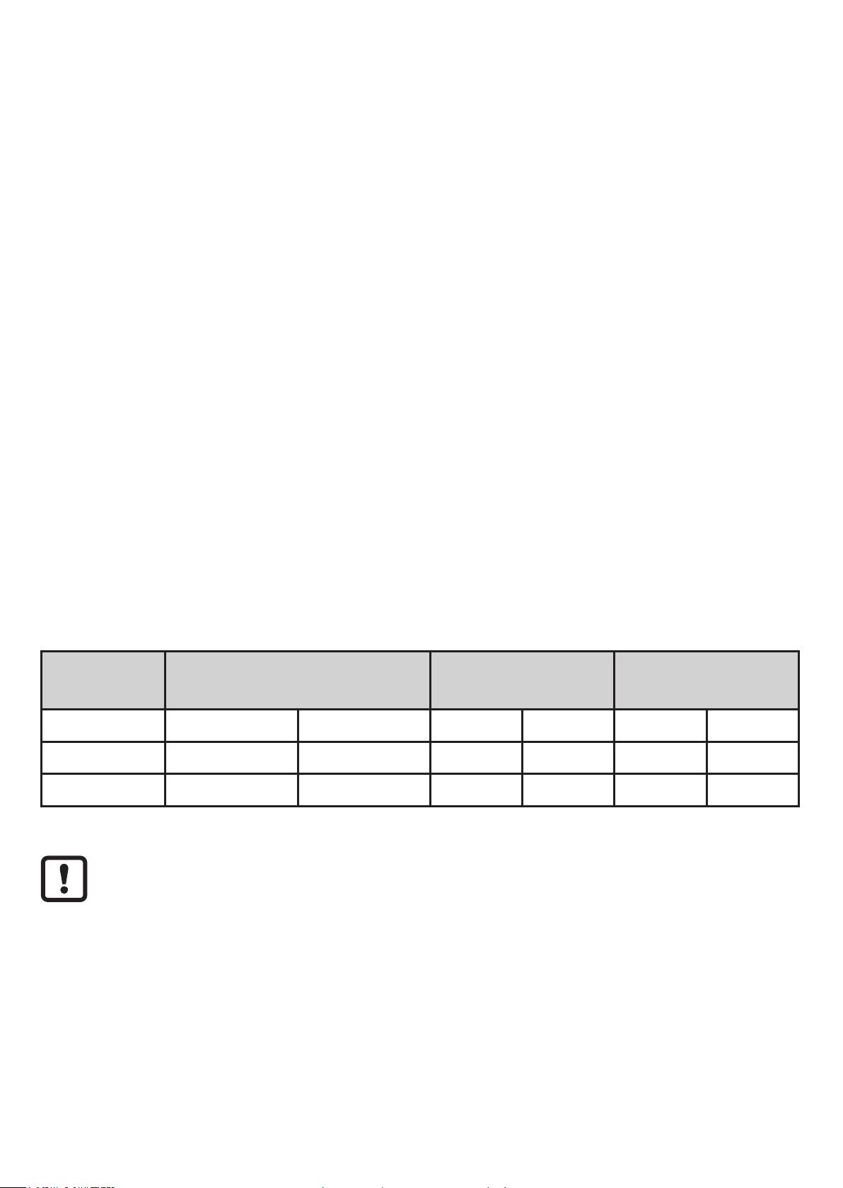
Order no. Measuring range
bar PSI bar PSI bar PSI
PQ7809 -1���1 -14�6���14�5 20 290 30 435
PQ7834 -1���10 -15���145 20 290 30 435
Avoid static and dynamic overpressure exceeding the given overload
Permissible
Bursting pressure
overpressure
MPa = bar ÷ 10 / kPa = bar × 100
4
pressure by taking appropriate measures�
The indicated bursting pressure must not be exceeded�
Even if the bursting pressure is exceeded only for a short time, the unit
may be destroyed� NOTE: Risk of injury!
4 Function
4.1 Processing of the measured signals
• The unit displays the current system pressure�
• It generates 2 output signals according to the parameter setting�
OUT1 • Switching signal for system pressure limit value�
2 options
OUT2
• Switching signal for system pressure limit value�
• Diagnostic signal (output 1 is inactive in case of a fault)�
UK
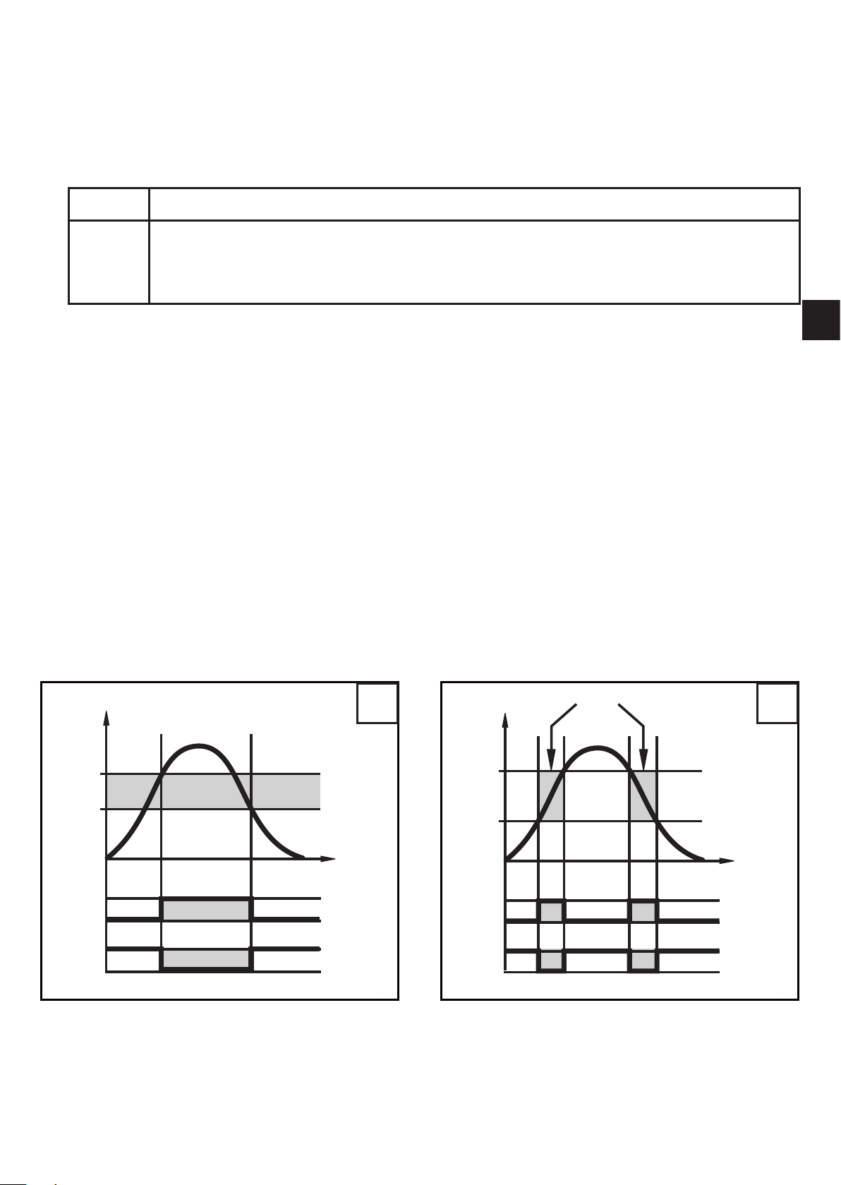
4.2 Switching function
OUTx changes its switching state if it is above or below the set switching limits
(SPx, rPx)� The following switching functions can be selected:
• Hysteresis function / normally open: [oux] = [Hno] (→ fig. 1).
• Hysteresis function / normally closed: [oux] = [Hnc] (→ fig. 1).
First the set point (SPx) is set, then the reset point (rPx) with the requested
difference�
• Window function / normally open: [oux] = [Fno] (→ fig. 2).
• Window function / normally closed: [oux] = [Fnc] (→ fig. 2).
The width of the window can be set by means of the difference between FHx and
FLx� FHx = upper value, FLx = lower value�
P = system pressure; HY = hysteresis; FE = window
1 2
5
4.3 Diagnostic function
Output 2 is used as diagnostic output based on the DESINA specification if
[ou2] = [diA]�
• If there is no fault, the output is switched and carries Ub+ �
• In case of malfunctions in the following areas, the output is inactive:
- short circuit in output 1�
- EPROM function�
- RAM function�
- parameter setting�
- processor function�
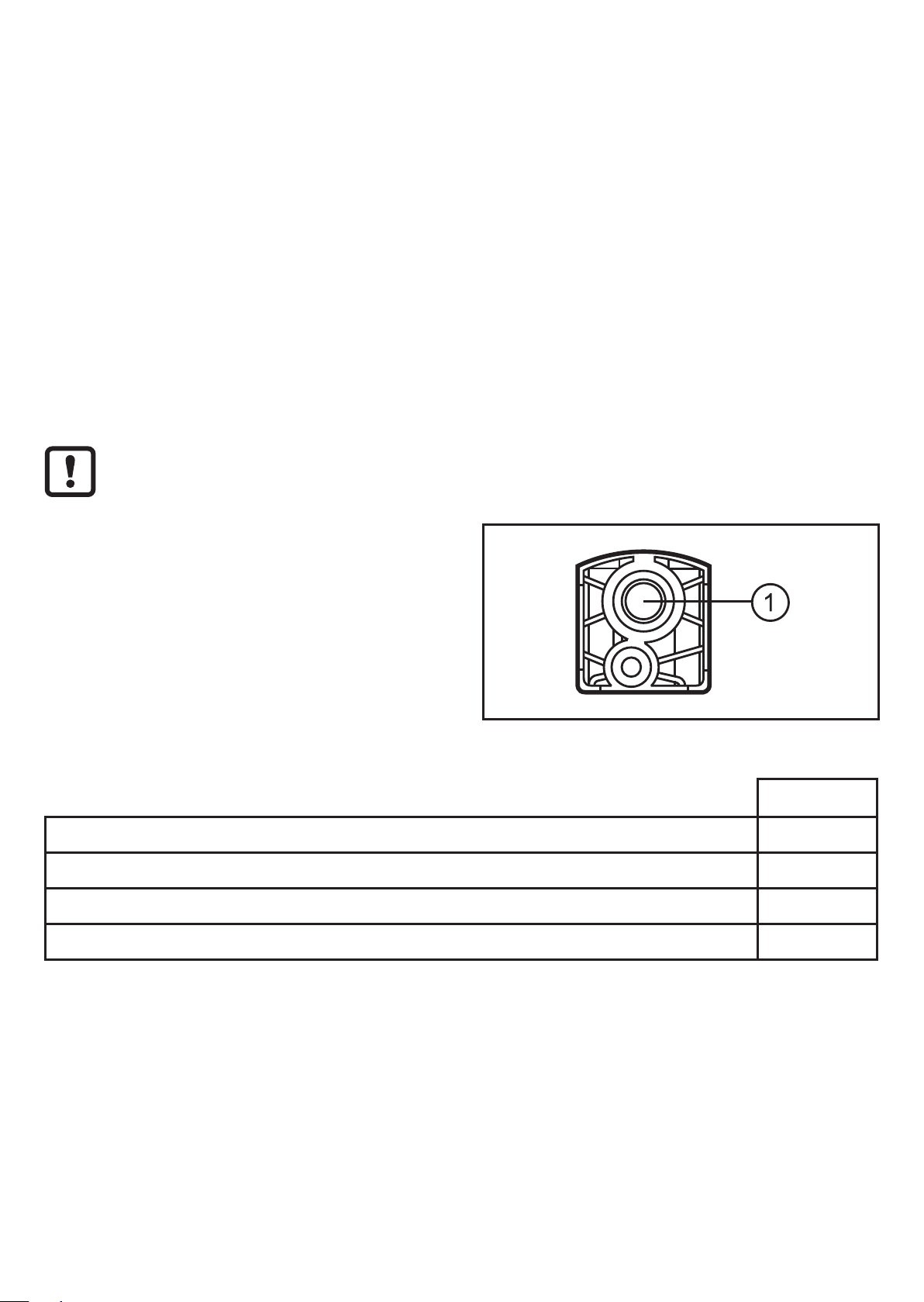
5 Mounting
Before installing and removing the unit: make sure that no pressure is
applied to the system�
► Screw the pressure connection or
adapter G⅛ to the main pressure
connection (1) and tighten�
Maximum tightening torque: 8 Nm�
Maximum thread length: 7�5 mm�
5.1 Mounting accessories
The following components are available as accessories:
Mounting set for DIN rail mounting (DIN rail TH 35-7�5 to EN 60715) E37340
Thread extension 1/8“ for flange mounting E30075
Push-in air fitting for tube Ø 6 mm E30076
Push-in air fitting for tube Ø 8 mm E30077
Order no�
6
 Loading...