

IFM Electronic PN7292, PN7271, PN 7270, PN7293, PN7296 Operating Instructions Manual
...
Operating instructions
Electronic pressure sensor
PN72xx
PN73xx
PN76xx
80012464 / 00 07 / 2016
UK

2
Contents
1 Preliminary note ��������������������������������������������������������������������������������������������������� 4
1�1 Symbols used ������������������������������������������������������������������������������������������������4
2 Safety instructions �����������������������������������������������������������������������������������������������4
3 Functions and features ����������������������������������������������������������������������������������������5
3�1 Applications ���������������������������������������������������������������������������������������������������5
4 Function ��������������������������������������������������������������������������������������������������������������� 7
4�1 Communication, parameter setting, evaluation ���������������������������������������������7
4�2 Switching function ������������������������������������������������������������������������������������������ 7
4�3 IO-Link �����������������������������������������������������������������������������������������������������������8
5 Installation������������������������������������������������������������������������������������������������������������9
6 Electrical connection �������������������������������������������������������������������������������������������� 9
7 Operating and display elements ������������������������������������������������������������������������10
8 Menu ������������������������������������������������������������������������������������������������������������������ 11
8�1 Menu structure: Main menu ������������������������������������������������������������������������� 11
8�2 Explanation of the menu ������������������������������������������������������������������������������ 12
8�2�1 Explanation of the menu level 1 ���������������������������������������������������������12
8�2�2 Explanation of the menu level 2 ���������������������������������������������������������12
9 Parameter setting ����������������������������������������������������������������������������������������������13
9�1 Parameter setting in general �����������������������������������������������������������������������13
9�2 Configure display (optional) ������������������������������������������������������������������������� 16
9�3 Set output signals ����������������������������������������������������������������������������������������16
9�3�1 Set output functions ���������������������������������������������������������������������������� 16
9�3�2 Define switching limits for the hysteresis function ������������������������������16
9�3�3 Define switching limits for the window function ����������������������������������17
9�4 User settings (optional) �������������������������������������������������������������������������������� 17
9�4�1 Set delay for the switching outputs ����������������������������������������������������� 17
9�4�2 Set output logic for the switching outputs ������������������������������������������� 17
9�4�3 Set damping for the switching signal �������������������������������������������������� 17
9�4�4 Read min/max values for the system pressure ����������������������������������17
9�4�5 Reset all parameters to factory setting �����������������������������������������������18
9�4�6 Set colour change of the display ������������������������������������������������������18
9�4�7 Graphical depiction of the colour change of the display ��������������������� 19

3
UK
10 Operation ��������������������������������������������������������������������������������������������������������� 21
10�1 Read set parameters ���������������������������������������������������������������������������������21
10�2 Self-diagnosis / error indications ���������������������������������������������������������������22
11 Technical data and scale drawing ��������������������������������������������������������������������24
11�1 Setting ranges �������������������������������������������������������������������������������������������� 24
11�2 Further technical data ��������������������������������������������������������������������������������25
12 Factory setting �������������������������������������������������������������������������������������������������25

4
1 Preliminary note
1.1 Symbols used
► Instructions
> Reaction, result
[…] Designation of keys, buttons or indications
→ Cross-reference
Important note
Non-compliance can result in malfunction or interference�
Information
Supplementary note�
2 Safety instructions
• Please read this document prior to set-up of the unit� Ensure that the product is
suitable for your application without any restrictions�
• If the operating instructions or the technical data are not adhered to, personal
injury and/or damage to property can occur�
• Check the compatibility of the product materials with the media to be measured
in all applications�
• Correct condition of the device for the operating time can only be guaranteed if
the device is only used for media to which the wetted materials are sufficiently
resistant → 3.1 Applications.
• If the devices are used in gas applications with pressures > 362 psi (25 bar)
the notes in chapter 3�1 for devices with the marking **
)
must be absolutely
observed�
The responsibility whether the measurement device is suitable for the respective application lies with the operator� The manufacturer assumes no
liability for consequences of misuse by the operator� Improper installation
and use of the devices results in a loss of the warranty claims�

5
UK
3 Functions and features
The device monitors the system pressure of machines and installations�
3.1 Applications
Type of pressure: relative pressure
Order no. Measuring range
Permissible
overpressure *
)
Bursting pres-
sure
psi bar psi bar psi bar
Pressure sensors with internal thread 1/4 - 18 NPT
PN7270 0…5800 0���400 11580 800 24650 1700
PN7271 0…3625 0���250 7250 500 17400 1200
PN7292** 0…1450 0���100 4350 300 9400 650
PN7293** 0…362 0���25 2175 150 5075 350
PN7294** -14�5…145 -1���10 1087 75 2175 150
PN7296 0…36�2 0���2�5 290 20 725 50
PN7297 0…14�5 0���1 145 10 450 30
PN7299 -14�5���14�5 -1���1 290 20 725 50
Pressure sensors with external thread 1/4 - 18 NPT
PN7670 0���5800 0���400 11580 800 24650 1700
PN7271 0…3625 0���250 7250 500 17400 1200
PN7692** 0���1450 0���100 4350 300 9400 650
PN7693** 0���362 0���25 2175 150 5075 350
PN7694** -14�5���145 -1���10 1087 75 2175 150
PN7696 0���36�2 0���2�5 290 20 725 50
PN7697 0���14�5 0���1 145 10 450 30
PN7699 -14�5���14�5 -1���1 290 20 725 50
Pressure sensors with internal thread 7/16“ - 20 UNF
PN7370 0���5800 0���400 11580 800 24650 1700
PN7392 0…1450 0���100 4350 300 9400 650
*
)
With static overload pressure or max� 100 million pressure cycles�
**
)
For gas applications > 362 psi (25 bar) it is necessary to use devices with a measuring
range ≥ 3620 psi (250 bar)!
MPa = (measured value in bar) ÷ 10
kPa = (measured value in bar) x 100

6
Avoid static and dynamic overpressure exceeding the specified overload
pressure by taking appropriate measures�
The indicated bursting pressure must not be exceeded�
Even if the bursting pressure is exceeded only for a short time, the unit
may be destroyed. ATTENTION: Risk of injury!
Pressure Equipment Directive (PED):
The units comply with section 3, article (3) of the Directive 97/23/EC and
are designed and manufactured for "non-superheated liquids" of group 2
fluids in accordance with the sound engineering practice�
Restriction for stable gases according to PED → 2 Safety instructions.

7
UK
4 Function
• The unit displays the current system pressure�
• It generates output signals according to the operating mode and the parameter
setting�
• It moreover provides the process data via IO-Link�
• The unit is laid out for fully bidirectional communication� So, the following
options are possible:
- Remote display: reading and display of the current system pressure�
- Remote parameter setting: reading and changing the current parameter
setting�
- IO-Link parameter setting → 4.3
4.1 Communication, parameter setting, evaluation
OUT1 (pin 4)
• Switching signal for system pressure limit value�
• Communication via IO-Link�
OUT2 (pin 2) • Switching signal for system pressure limit value�
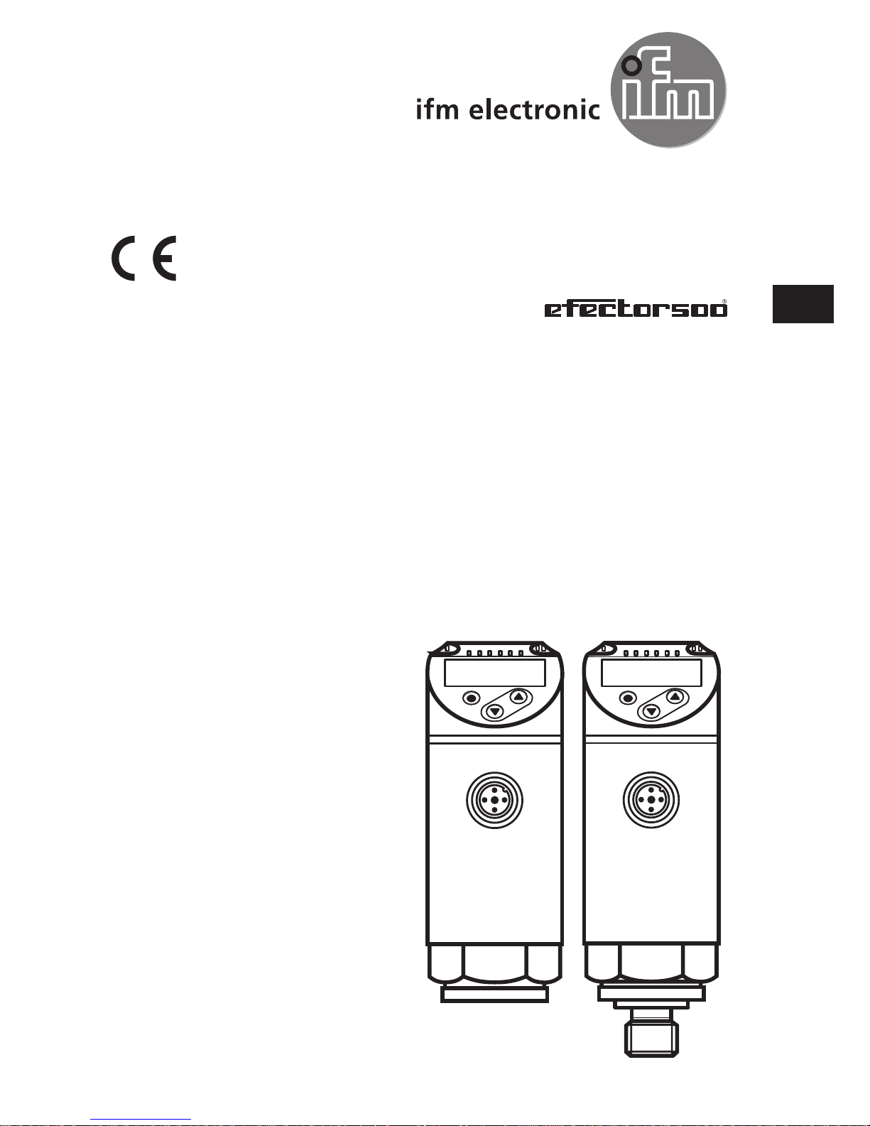
4.2 Switching function
OUTx changes its switching state if it is above or below the set switching limits
(SPx, rPx)� The following switching functions can be selected:
• Hysteresis function / normally open: [oux] = [Hno] (→ fig. 1).
• Hysteresis function / normally closed: [oux] = [Hnc] (→ fig. 1).
First the set point (SPx) is set, then the reset point (rPx)�
The hysteresis defined remains even if SPx is changed again�
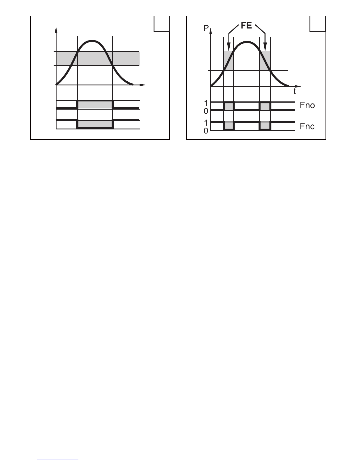
• Window function / normally open: [oux] = [Fno] (→ fig. 2).
• Window function / normally closed: [oux] = [Fnc] (→ fig. 2).
The width of the window can be set by means of the difference between FHx
and FLx� FHx = upper value, FLx = lower value�
8
FH
FL
1 2
P = system pressure; HY = hysteresis; FE = window
4.3 IO-Link
General information
This unit has an IO-Link communication interface which requires an IO-Linkcapable module (IO-Link master) for operation�
The IO-Link interface enables direct access to the process and diagnostic data
and provides the possibility to set the parameters of the unit during operation�
In addition communication is possible via a point-to-point connection with a USB
adapter cable�
Further information about IO-Link at www.ifm.com → more product information →
Specials → IO-Link.
Device-specific information
You can find the IODDs necessary for the configuration of the IO-Link unit and
detailed information about process data structure,
diagnostic information and parameter addresses at www.ifm.com → more product
information → Specials → IO-Link.
Parameter setting tools
You will find all necessary information about the required IO-Link hardware and
software at www.ifm.com → more product information → Specials → IO-Link.
 Loading...