

IFM Electronic PL2058 Operating Instructions Manual
Bedienungsanleitung
Operating instructions
Notice utilisateurs
Elektronischer
Drucksensor
Electronic pressure
sensor
Capteur de pression
électronique
PL2058
R
DEUTSCHENGLISHFRANÇAIS
Sachnr. 701712/00 08/02

12
Contents
Installation . . . . . . . . . . . . . . . . . . . . . . . . . . . . . . . . . page 14
Electrical connection . . . . . . . . . . . . . . . . . . . . . . . . . page 15
Installation and set-up / operation / maintenance . . . . . page 16
Function . . . . . . . . . . . . . . . . . . . . . . . . . . . . . . . . . . page 17
Electrical connection . . . . . . . . . . . . . . . . . . . . . . . . . page 18
Adjustable parameters . . . . . . . . . . . . . . . . . . . . . . . . page 19
Technical data . . . . . . . . . . . . . . . . . . . . . . . . . . . . . . page 20
Scaling the measuring range . . . . . . . . . . . . . . . . . . . . page 21
Scale drawing . . . . . . . . . . . . . . . . . . . . . . . . . . . . . . page 32
1 Function and features . . . . . . . . . . . . . . . . . . . . . . page 13
4 Technical informations / Functioning / Parameters page 19
3 Programming / Use with EPS interface . . . . . . . . . page 17
2 Use with factory setting . . . . . . . . . . . . . . . . . . . . page 14
Safety instructions
Please read the product description prior to installing the unit.
Please check that the product is suitable for your application
without any restrictions.
If the operating instructions or the technical data are not
adhered to, personal injury and/or damage to property may
occur.
Please check in all applications that the product materials (see
Technical data) are compatible with the media to be measured.
The pressure sensor detects the system pressure and converts it into
an analog output signal (4 ... 20 mA). The measuring range can be
scaled to up to 25% of the value of the span (→ page 19, 21).
It is also indicated:
• System pressure above the measuring range: output signal > 20 mA.
• System pressure below the measuring range: output signal drops to
max. 3.2 mA (depending on the scaling).
Applications :
Avoid static and dynamic overpressure exceeding the given overload pressure.
Even if the bursting pressure is exceeded only for a short time
the unit can be destroyed (danger of injuries)!
The unit is ready for operation when delivered.
Factory preset: not scaled.
13
1Function and features
ENGLISH
Bursting
pressure
Permissible
overl. pressure
Measuring range
-12.5 ... 250.0 10000 (10 bar) 30000 (30 bar)
-1.25 ... 25.00 1000 (1 MPa) 3000 (3 MPa)
mbar
kPa
-5.0 ... 100.4 4000 12000
-125 ... 2550 102000 306000
inH2O
mmWS
Installation
Before mounting and removing the sensor, make sure that no pressure
is applied to the system.
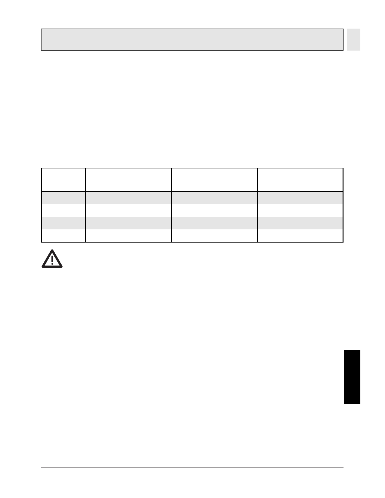
The unit is adaptable for various
process fittings. ifm adapters to
be ordered separately as accessories.
Mount adapter (C) to the sensor
(A) first, then sensor + adapter to
the process connection by means
of a nut, a clamping flange or
similar (B).
If it is not possible to slide the fixing element (B) down over the
top of the sensor: slide it up over
the bottom of the sensor before
the adapter is mounted.
Note: Sensor and adapter are only to be mounted once.
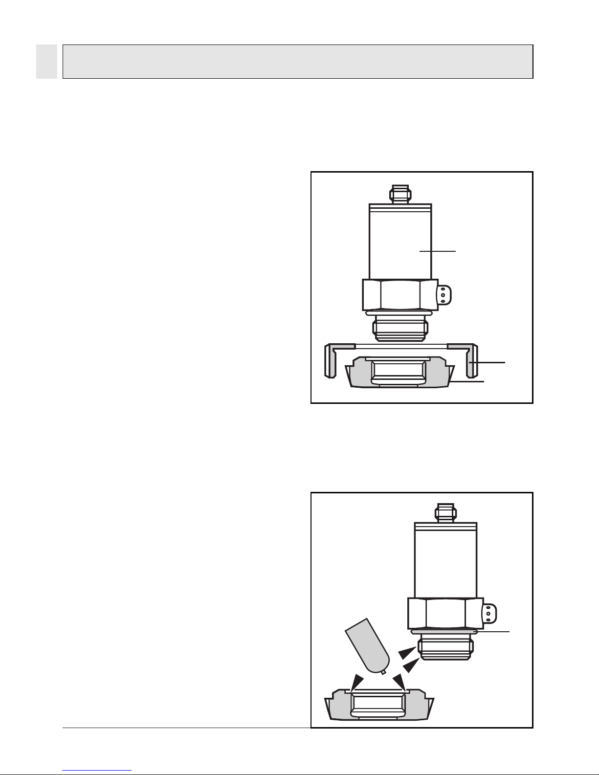
Mounting of the adapter
Step 1
Grease thread and sealing chamfer of the sensor and of the
adapter with the greasing paste
supplied.
The greasing paste is food-grade
(USDA-H1 84-201).
Make sure that the O-ring (D) is
correctly positioned.
14
2
A
B
C
D
Grease
Use with factory setting
 Loading...