

IFM Electronic PI22, PI23 Operating Instructions Manual
Operating instructions
Electronic pressure sensor
PI22xx
PI23xx
80009157 / 01 07 / 2018
UK

2
Contents
1 Preliminary note ��������������������������������������������������������������������������������������������������� 4
1�1 Symbols used ������������������������������������������������������������������������������������������������4
2 Safety instructions �����������������������������������������������������������������������������������������������4
3 Functions and features ����������������������������������������������������������������������������������������5
3�1 Applications ���������������������������������������������������������������������������������������������������5
4 Function ��������������������������������������������������������������������������������������������������������������� 5
4�1 Operating modes �������������������������������������������������������������������������������������������6
4�1�1 2-wire operation ������������������������������������������������������������������������������������ 6
4�1�2 3-wire operation ������������������������������������������������������������������������������������ 6
4�2 Switching function (only for 3-wire operation) ������������������������������������������������6
4�3 Analogue function ������������������������������������������������������������������������������������������7
4�4 Customer-specific calibration ������������������������������������������������������������������������8
4�5 IO-Link ���������������������������������������������������������������������������������������������������������10
4�5�1 General information ����������������������������������������������������������������������������10
4�5�2 Device-specific information �����������������������������������������������������������������10
4�5�3 Parameter setting tools �����������������������������������������������������������������������10
5 Installation����������������������������������������������������������������������������������������������������������10
5�1 Connection versions clamp seals ���������������������������������������������������������������10
6 Electrical connection ������������������������������������������������������������������������������������������ 12
6�1 Connection for 2-wire operation ������������������������������������������������������������������12
6�2 Connection for IO-Link parameter setting ����������������������������������������������������12
6�3 Connection for 3-wire operation ������������������������������������������������������������������13
7 Operating and display elements ������������������������������������������������������������������������14
8 Menu ������������������������������������������������������������������������������������������������������������������ 15
8�1 Menu structure: main menu ������������������������������������������������������������������������� 15
8�2 Explanation of the main menu ���������������������������������������������������������������������16
8�3 Menu structure: level 2 (extended functions) �����������������������������������������������17
8�4 Explanation of menu level 2 ������������������������������������������������������������������������18
8�5 Menu structure: level 3 (simulation) �������������������������������������������������������������19
8�6 Explanation of menu level 3 ������������������������������������������������������������������������20
9 Parameter setting ����������������������������������������������������������������������������������������������21
9�1 Parameter setting in general �����������������������������������������������������������������������21

3
UK
9�2 Configure display (optional) ������������������������������������������������������������������������� 23
9�3 Set output signals ����������������������������������������������������������������������������������������24
9�3�1 Set output functions ���������������������������������������������������������������������������� 24
9�3�2 Set switching limits �����������������������������������������������������������������������������24
9�3�3 Scale analogue value for OUT2 ���������������������������������������������������������25
9�4 User settings (optional) �������������������������������������������������������������������������������� 26
9�4�1 Carry out zero point calibration ����������������������������������������������������������26
9�4�2 Set output status in fault condition ������������������������������������������������������26
9�4�3 Set delay time for the switching outputs ��������������������������������������������� 26
9�4�4 Set output logic for the switching outputs ������������������������������������������� 26
9�4�5 Set damping for the switching signal �������������������������������������������������� 27
9�4�6 Set damping for the analogue signal �������������������������������������������������� 27
9�4�7 Calibrate curve of measured values ���������������������������������������������������27
9�5 Service functions �����������������������������������������������������������������������������������������28
9�5�1 Read min/max values for the system pressure ����������������������������������28
9�5�2 Reset all parameters to factory setting �����������������������������������������������28
9�6 Simulation function ��������������������������������������������������������������������������������������28
9�6�1 Open menu level 3 (simulation) ���������������������������������������������������������� 28
9�6�2 Set simulation value ���������������������������������������������������������������������������29
9�6�3 Set time for simulation ������������������������������������������������������������������������29
9�6�4 Start simulation ����������������������������������������������������������������������������������� 29
10 Operation ��������������������������������������������������������������������������������������������������������� 30
10�1 Read the set parameters ���������������������������������������������������������������������������30
10�2 Change the display in the Run mode �������������������������������������������������������30
10�3 Self-diagnostics / fault indications �������������������������������������������������������������30
11 Technical data ��������������������������������������������������������������������������������������������������33
11�1 Setting ranges �������������������������������������������������������������������������������������������� 33
11�2 Technical data ��������������������������������������������������������������������������������������������33
12 Factory setting �������������������������������������������������������������������������������������������������34

4
1 Preliminary note
1.1 Symbols used
► Instructions
> Reaction, result
[…] Designation of keys, buttons or indications
→ Cross-reference
Important note
Non-compliance may result in malfunction or interference�
Information
Supplementary note�
2 Safety instructions
• Read this document before setting up the product and keep it during the entire
service life�
• The product must be suitable for the corresponding applications and
environmental conditions without any restrictions�
• Only use the product for its intended purpose
(→ Functions and features).
• Only use the product for permissible media (→ Technical data).
• If the operating instructions or the technical data are not adhered to, personal
injury and/or damage to property may occur�
• The manufacturer assumes no liability or warranty for any consequences
caused by tampering with the product or incorrect use by the operator�
• Installation, electrical connection, set-up, operation and maintenance of the
product must be carried out by qualified personnel authorised by the machine
operator�
• Protect units and cables against damage�
5
UK
3 Functions and features
The unit measures and monitors the system pressure in a plant�
3.1 Applications
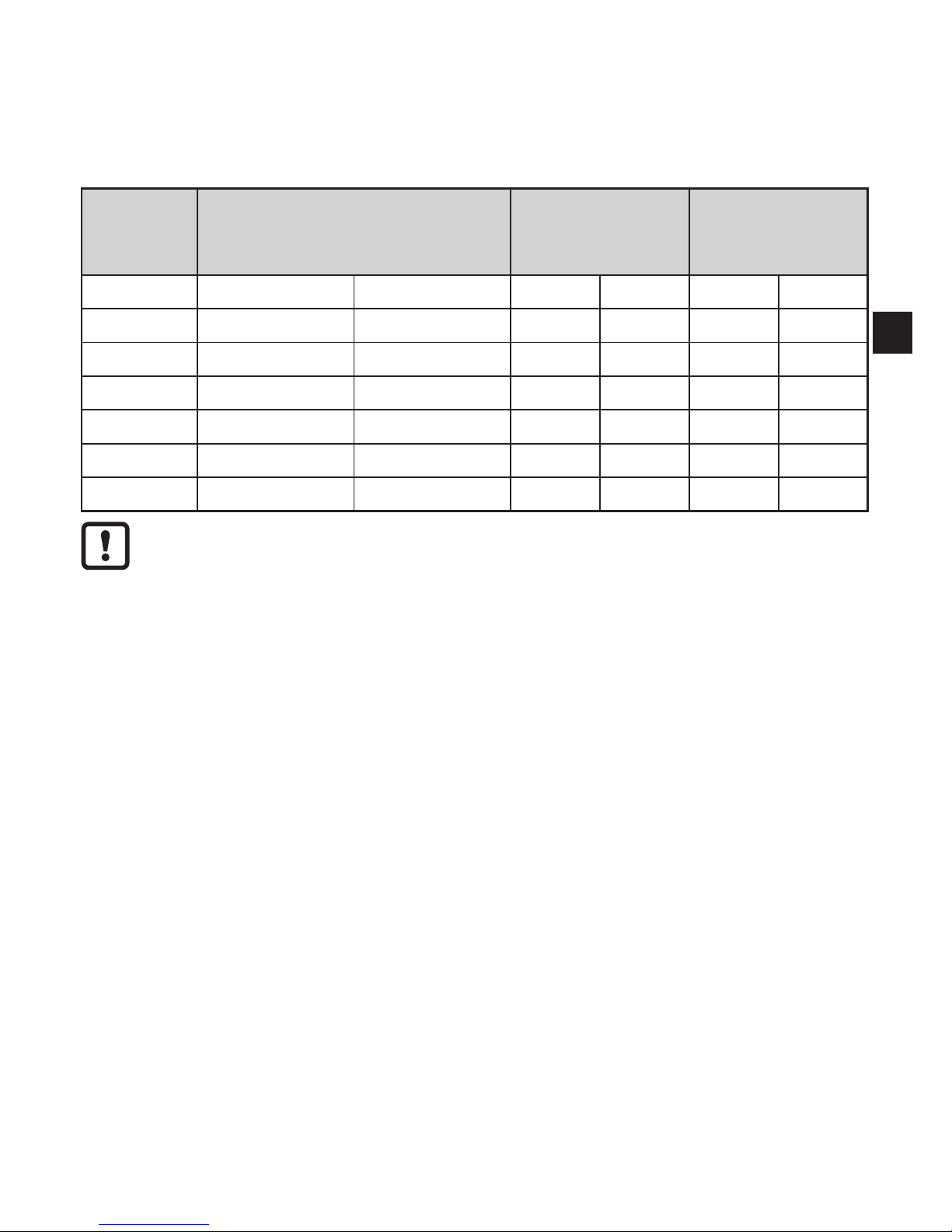
Type of pressure: relative pressure
Order no. Measuring range
Permissible
overload
pressure
Bursting
pressure
bar PSI bar PSI bar PSI
PI2xx9 -1���1 -14�5���14�5 10 145 30 435
PI2xx7 -0�05���1 -0�73���14�5 10 145 30 435
PI2xx6 -0�124���2�5 -1�8���36�27 20 290 50 725
PI2xx5 -1���4 -14�5���58 30 435 50 725
PI2xx4 -1���10 -14�5���145 50 725 100 1450
PI2xx3 -1���25 -14�4���362�7 80 1160 150 2175
Avoid static and dynamic overpressure exceeding the specified overload
pressure by taking appropriate measures�
The indicated bursting pressure must not be exceeded�
Even if the bursting pressure is exceeded only for a short time, the unit
may be destroyed� ATTENTION: risk of injury!
Not suitable for use where the criteria for paragraph D10�2/63-03 of the 3-A
standard 63-03 have to be met�
4 Function
• The unit displays the current system pressure�
• It generates output signals according to the operating mode and the parameter
setting�
• Moreover, it provides the process data via IO-Link�
• The unit is designed for fully bidirectional communication�
So the following options are possible:
- Remote display: reading and display of the current system pressure�
- Remote parameter setting: reading and changing the current parameter
setting�
- IO-Link parameter setting (→ 4.5)

6
4.1 Operating modes
The operating mode is defined by the wiring (→ 6 Electrical connection) and
automatically recognised by the unit�
4.1.1 2-wire operation
OUT2 (pin 2) Analogue signal proportional to pressure 4…20 mA or 20���4 mA
4.1.2 3-wire operation
OUT1 (pin 4)
• Switching signal for system pressure limit
• Communication via IO-Link
OUT2 (pin 2)
3 options:
• Switching signal for system pressure limit
• Analogue signal proportional to pressure 4���20 mA
• Analogue signal proportional to pressure 20���4 mA
4.2 Switching function (only for 3-wire operation)
OUTx changes its switching status if it is above or below the set switching limits
(SPx, rPx)� The following switching functions can be selected:
• Hysteresis function / normally open: [OUx] = [Hno] (→ fig. 1).
• Hysteresis function / normally closed: [OUx] = [Hnc] (→ fig. 1).
First the set point (SPx) is set, then the reset point (rPx) with the requested
difference�
• Window function / normally open: [OUx] = [Fno] (→ fig. 2).
• Window function / normally closed: [OUx] = [Fnc] (→ fig. 2).
The width of the window can be set by means of the difference between SPx
and rPx� SPx = upper value, rPx = lower value�
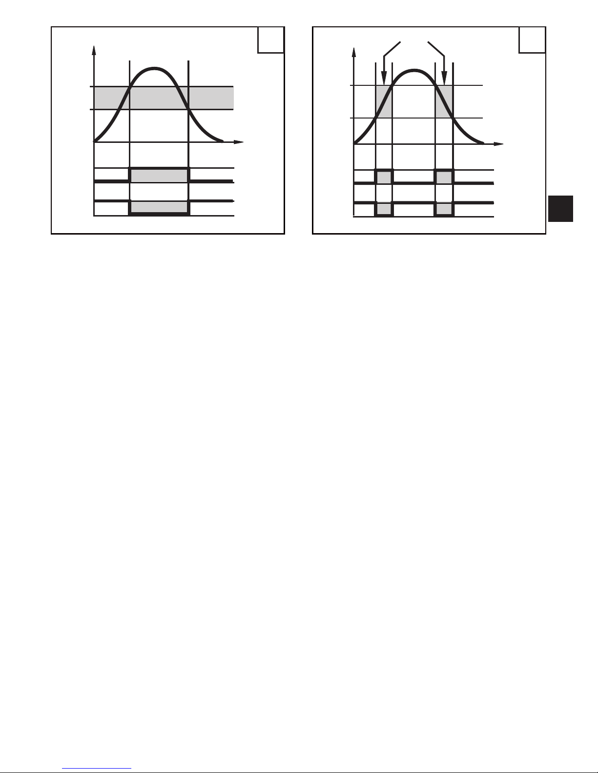
7
UK
1 2
P = system pressure; HY = hysteresis; FE = window
4.3 Analogue function
The analogue output can be configured�
• [OU2] defines whether the set measuring range is provided as 4���20 mA
([OU2] = [I]) or as 20���4 mA ([OU2] = [InEG])�
Scaling can be set by means of the teach process or by entering a value for the
parameters ASP and AEP�
• Teaching the analogue start point [tASP] or setting the parameter [ASP] defines
at which measured value the output signal is 4 mA (20 mA with [InEG])�
• Teaching the analogue end point [tAEP] or setting the parameter [AEP] defines
at which measured value the output signal is 20 mA (4 mA with [InEG])�
8
Minimum distance between [ASP] and [AEP] = 25 % of the final value of the
measuring range (turn-down 1:4); for PI2x09: 25 % of the measuring span�
Factory setting Measuring range scaled
P = system pressure , MAW = initial value of the measuring range, MEW = final value of
the measuring range
1
: [OU2] = [I] 2: [OU2] = [InEG]
In the set measuring range the output signal is between 4 and 20 mA ([OU2] = [I])
or between 20 and 4 mA ([OU2] = [InEG])�
It is also indicated:
• System pressure above the measuring range:
- Output signal > 20 mA if [OU2] = [I]�
- Output signal 4 to 3�8 mA if [OU2] = [InEG]�
• System pressure below the measuring range:
- Output signal 4 to 3�8 mA if [OU2] = [I]�
- Output signal > 20 mA if [OU2] = [InEG]�
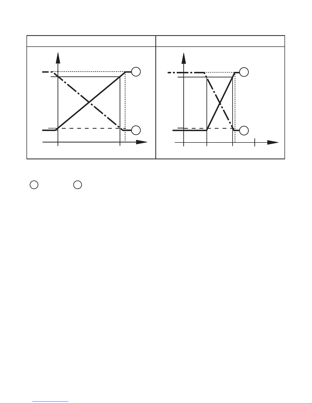
4.4 Customer-specific calibration
The customer-specific calibration changes the curve of measured values
compared to the real measured values (shifting / change of the gradient → 9.4.6
[CAL])�
• Two calibration points can be defined (CP1, CP2)� The two points are
independent of each other�
• The two calibration points must be within the scaled measuring range (→ 4.3
Pressure monitoring / analogue function)�
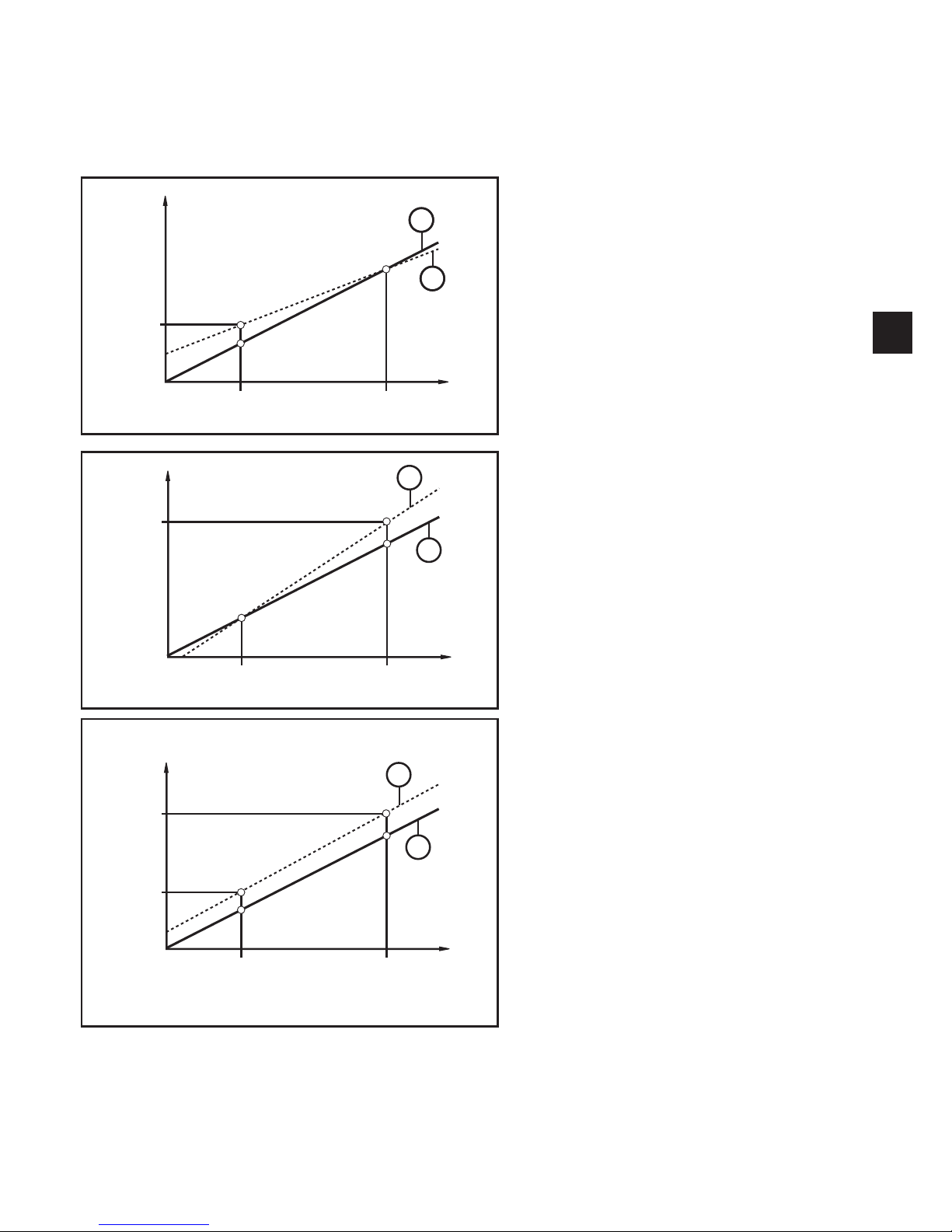
9
UK
• The zero point calibration [COF] influences the calibration of the curve of
measured values. Recommendation: set [COF] to 0 (→ 9.4.1 [COF]), then
calibrate the curve of measured values�
After a change the calibration can be reset to factory setting (→ 9.5.2 [rES]).
• P = measured pressure
P‘ = modified measured value
• CP1 = calibration point 1
CP1‘ = modified measured value for
CP1
• CP2 = calibration point 2
• 1 = curve of measured values with
factory setting
• 2 = curve of measured values after
calibration
• P = measured pressure
P‘ = modified measured value
• CP1 = calibration point 1
CP2 = calibration point 2
CP2‘ = modified measured value for
CP2
• 1 = curve of measured values with
factory setting
• 2 = curve of measured values after
calibration
• P = measured pressure
P‘ = modified measured value
• CP1 = calibration point 1
CP1‘ = modified measured value for
CP1
• CP2 = calibration point 2
CP2‘ = modified measured value for
CP2
• 1 = curve of measured values with
factory setting
• 2 = curve of measured values after
calibration
10
4.5 IO-Link
4.5.1 General information
This unit has an IO-Link communication interface which requires an IO-Linkcapable module (IO-Link master) for operation�
The IO-Link interface enables direct access to the process and diagnostic data
and provides the possibility to set the parameters of the unit during operation�
In addition, communication is possible via a point-to-point connection with a USB
adapter cable�
More information about IO-Link → www�ifm�com�
4.5.2 Device-specific information
IODDs necessary for the configuration of the IO-Link unit and detailed information
about process data structure, diagnostic information and parameter addresses →
www�ifm�com�
4.5.3 Parameter setting tools
All necessary information about the required IO-Link hardware and software →
www�ifm�com�
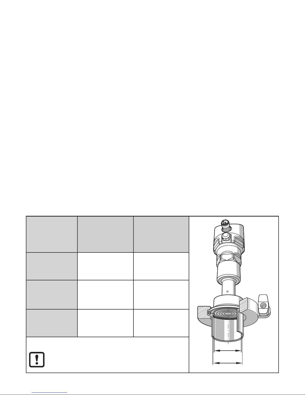
5 Installation
5.1 Connection versions clamp seals
Clamp
connection to
pipe to DIN
11866
Effective diameter
PI22xx:
Deff = 34 mm
Effective diameter
PI23xx:
Deff = 47�5 mm
d
1
d
2
Series A - metric nominal width
DN 40
Di = 38 mm
nominal width
DN 50
Di = 50 mm
Series B - ISO nominal width
DN / OD 42�4
Di = 38�4 mm
--------------------
Series C -
ASME
nominal width
DN / OD 1 ½“
Di = 34�8 mm
nominal width
DN / OD 2“
Di = 47�5 mm
Internal pipe diameter Di (d2) > diameter of the
effective area of the diaphragm Deff (d1)�
11
UK
► Before installing and removing the unit: Make sure that no pressure
is applied to the system� Please note when the system pressure is
displayed in % of the span: "0" does not mean that no pressure is
applied to the system!
► The diaphragm must not be dented or cleaned with pointed or hard
objects!
► The system seal must not be in contact with the diaphragm�
The installation position of the sensor influences the hydrostatic pressure
of the fill fluid in the capillary tube of the diaphragm seal unit� A zero shift
(i�e� when no pressure is applied to the system, "zero" is not displayed
as a measured value) as a consequence of the installation position of the
sensor can be corrected via the menu (→ 9.4.1)�
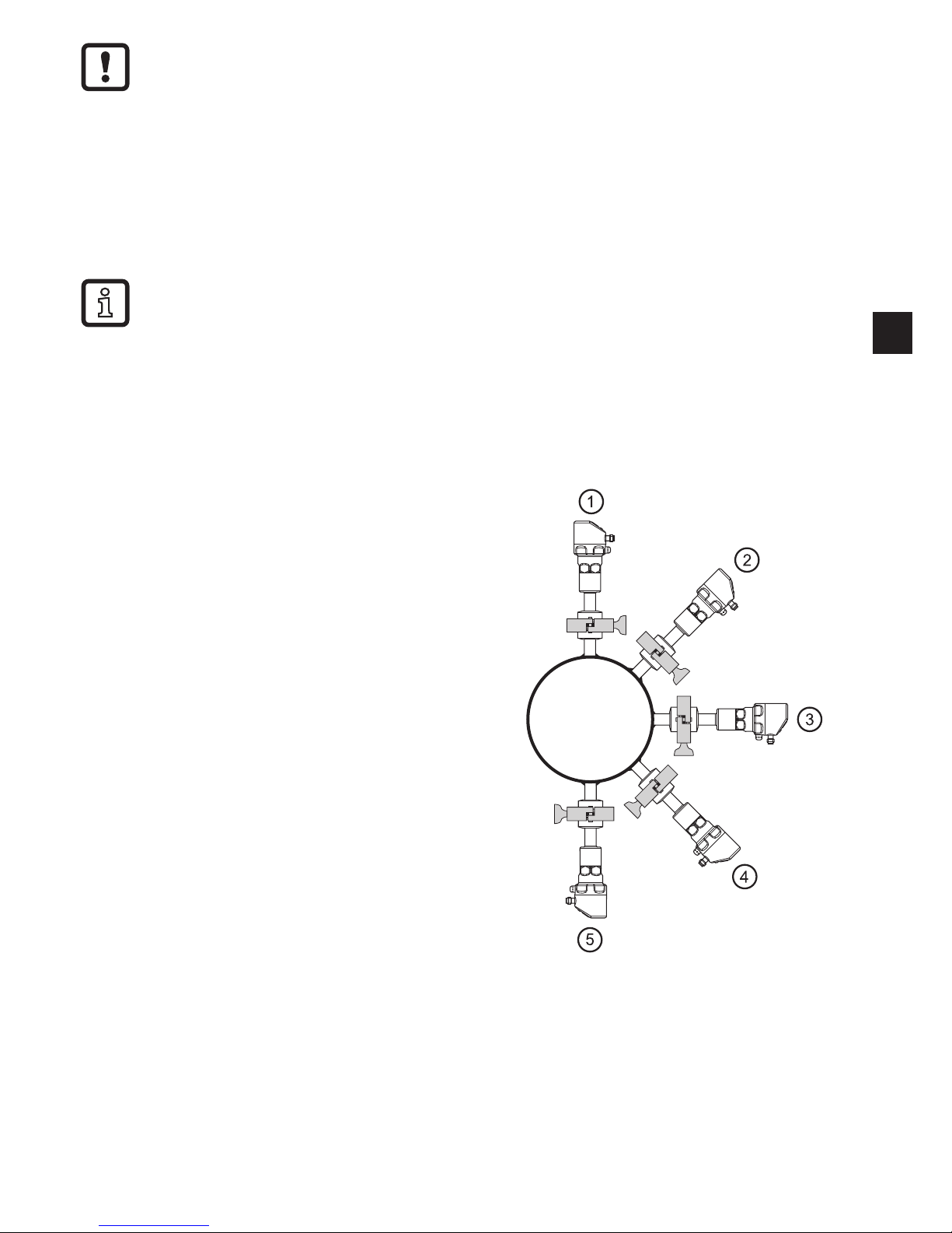
Use in hygienic areas to 3-A: orientation of the unit in pipes and tanks
Please note for optimised cleaning of
the measuring element according to
the 3-A criteria for hygienic areas:
To ensure that the medium can
completely flow off the area of the
diaphragm seal when the pipes or
tanks are empty, choose positions 1 - 3
of the generally possible installation
positions 1 - 5 (see figure on the right)�
Use in hygienic areas to EHEDG:
► Make sure that the sensor is integrated into the system according to EHEDG�
► Use seals with defined seal compression!
 Loading...