

Page 1

UK
UK
Operating instructions
Electronic manometer
PG28xx
704922 / 01 11 / 2010
Page 2

2
Contents
1 Preliminary note ���������������������������������������������������������������������������������������������������3
1�1 Symbols used ������������������������������������������������������������������������������������������������3
2 Safety instructions �����������������������������������������������������������������������������������������������4
3 Functions and features ����������������������������������������������������������������������������������������4
3�1 Applications ���������������������������������������������������������������������������������������������������4
4 Function ���������������������������������������������������������������������������������������������������������������5
4�1 Processing of the measured signals ��������������������������������������������������������������5
4�2 Pressure monitoring / switching function �������������������������������������������������������5
4�3 Pressure monitoring / analogue function ������������������������������������������������������� 6
4�4 Customer-specific calibration ������������������������������������������������������������������������7
5 Installation������������������������������������������������������������������������������������������������������������8
6 Electrical connection ��������������������������������������������������������������������������������������������9
7 Operating and display elements ������������������������������������������������������������������������10
8 Menu ������������������������������������������������������������������������������������������������������������������ 11
8�1 Menu structure: main menu ������������������������������������������������������������������������� 11
8�2 Explanation of the main menu ���������������������������������������������������������������������12
8�3 Menu structure: level 2 (extended functions) �����������������������������������������������13
8�4 Explanation of the menu level 2 ������������������������������������������������������������������14
9 Parameter setting ����������������������������������������������������������������������������������������������15
9�1 General parameter setting ���������������������������������������������������������������������������15
9�2 Configuration of the digital display (optional) �����������������������������������������������17
9�3 Set output signals ����������������������������������������������������������������������������������������18
9�3�1 Set output functions ����������������������������������������������������������������������������18
9�3�2 Set switching limits ����������������������������������������������������������������������������18
9�3�3 Scale analogue value for OUT2 ���������������������������������������������������������18
9�4 User settings (optional) ��������������������������������������������������������������������������������19
9�4�1 Carry out zero point calibration ����������������������������������������������������������19
9�4�2 Set delay time for OUT1 ���������������������������������������������������������������������19
9�4�3 Set switching logic for OUT1 ��������������������������������������������������������������19
9�4�4 Set damping for the switching signal ��������������������������������������������������19
9�4�5 Set damping for the analogue signal ��������������������������������������������������20
9�4�6 Calibrate curve of measured values ���������������������������������������������������20
Page 3

3
UK
1 Preliminary note
1.1 Symbols used
► Instruction
> Reaction, result
[…] Designation of pushbuttons, buttons or indications
→ Cross-reference
Important note
Non-compliance can result in malfunctions or interference�
Information
Supplementary note�
9�5 Service functions �����������������������������������������������������������������������������������������21
9�5�1 Read min/max values for system pressure ����������������������������������������21
9�5�2 Reset all parameters to factory setting �����������������������������������������������21
10 Operation ���������������������������������������������������������������������������������������������������������21
10�1 Read set parameters ���������������������������������������������������������������������������������21
10�2 Error indications �����������������������������������������������������������������������������������������21
11 Scale drawing �������������������������������������������������������������������������������������������������22
12 Technical data ��������������������������������������������������������������������������������������������������23
13 Setting ranges��������������������������������������������������������������������������������������������������25
14 Factory setting �������������������������������������������������������������������������������������������������26
Page 4
4
2 Safety instructions
• Please read this document prior to set-up of the unit. Ensure that the product is
suitable for your application without any restrictions.
• If the operating instructions or the technical data are not adhered to, personal
injury and/or damage to property can occur.
• Check the compatibility of the product materials (→ 12 Technical data) with the
media to be measured in all applications.
• Use in gases at pressures > 25 bar only after contacting the manufacturer ifm.
• The unit must only be installed in a process connection for G1 sealing cones
(e.g. ifm welding adapter, order no. E30013).
If the unit is installed in a 1“ thread without sealing cone, this will lead to seal
failure. Please use the PG27xx series in these applications.
• The device shall be supplied from an isolating transformer having a secondary
Listed fuse rated either
• a) max 5 amps for voltages 0~20 Vrms (0~28.3 Vp) or
• b) 100/Vp for voltages of 20~30 Vrms (28.3~42.4 Vp).
3 Functions and features
The unit monitors the system pressure in a plant.
3.1 Applications
Type of pressure: relative pressure
Order no.
Measuring range
(in brackets:
extended display range)
Permissible
overpressure
Bursting
pressure
bar PSI bar PSI bar PSI
PG2893 -1...25 (40) -14.4...362.7 (580.2) 100 1450 350 5070
PG2894 -1...10 (16) -14.5...145 (232) 50 725 150 2175
PG2895 -1...4 (6.4) -14.5...58 (92.8) 30 435 100 1450
PG2896 -0.124...2.5 (4) -1.8...36.27 (58.02) 20 290 50 725
PG2897 -0.05...1 (1.6) -0.73...14.5 (23.21) 10 145 30 435
PG2899 -1...1 (1.6) -14.5...14.5 (23.20) 10 145 30 435
mbar inH2O bar PSI bar PSI
PG2898 -12.4...250 (400) -5.0...100.4 (160.6) 10 145 30 435
PG2889 -5...100 (160) -2.0...40.15 (64.25) 4 58 30 435
Page 5
5
UK
Avoid static and dynamic overpressure exceeding the given overload pressure by taking appropriate measures.
The indicated bursting pressure must not be exceeded.
Even if the bursting pressure is exceeded only for a short time, the unit
may be destroyed. ATTENTION: risk of injury!
Use in gases at pressures > 25 bar only after contacting the manufacturer ifm.
The unit can be operated at media temperatures up to 145°C (max. 1h) /
125°C (permanently). Therefore it is suitable for all standard cleaning and
sterilisation processes (CIP, SIP).
4 Function
4.1 Processing of the measured signals
• The unit generates 2 output signals according to the parameter settings.
OUT1 • Switching signal for system pressure limit value.
OUT2 • Analogue signal (4...20 mA, 20...4 mA).
• The unit displays the current system pressure.
Analogue display: circular scale with pointer
Digital display (alphanumeric display, 4 digits).
In addition, an LED ring with one of the following display options is available:
- Trend display (rising pressure / falling pressure).
- Display of set point and reset point.
- Maximum value memory and minimum value memory.
- Display of pulsating signals and pressure peaks.
The display function is set via the menu → 9.2 / LED.
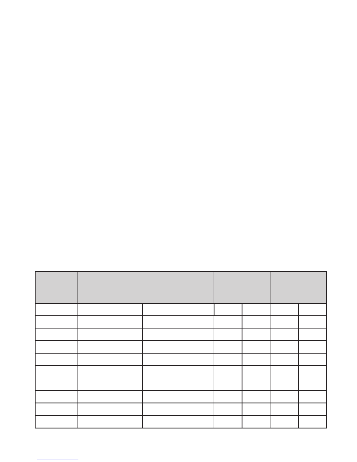
4.2 Pressure monitoring / switching function
OUT1 changes its switching state if it is above or below the set switching limits
(SP1, rP1). The following switching functions can be selected:
• Hysteresis function / normally open: [OU1] = [Hno] (→ fig. 1).
• Hysteresis function / normally closed: [OU1] = [Hnc] (→ fig. 1).
First the set point (SP1) is set, then the reset point (rP1) with the requested
difference.
• Window function / normally open: [OU1] = [Fno] (→ fig. 2).
• Window function / normally closed: [OU1] = [Fnc] (→ fig. 2).
The width of the window can be set by means of the difference between SP1
and rP1. SP1 = upper value, rP1 = lower value.
Page 6
6
1 2
P = system pressure; HY = hysteresis; FE = window
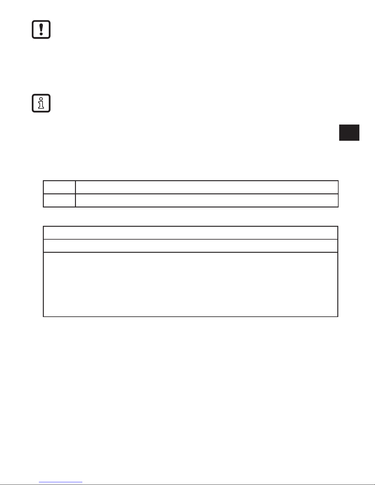
4.3 Pressure monitoring / analogue function
The analogue output can be configured: [OU2] defines whether the set measuring
range is provided as 4���20 mA ([OU2] = [I]) or as 20���4 mA ([OU2] = [InEG])�
Scaling can be set by means of the teaching process or by entering a value for the
ASP and AEP parameters�
• Teaching the analogue start point [tASP] or setting the parameter [ASP] defines
at which measured value the analogue signal is 4 mA (20 mA at [InEG])�
• Teaching the analogue end point [tAEP] or setting the parameter [AEP] defines
at which measured value the output signal is 20 mA (4 mA at [InEG])�
Minimum distance between [ASP] and [AEP] = 25 % of the final value of the
measuring range�
Factory setting Measuring range scaled
P = system pressure , MAW = initial value / MEW = final value of the measuring range
1
: [OU2] = [I]; 2: [OU2] = [InEG]
Page 7
7
UK
In the set measuring range the output signal is between 4 and 20 mA ([OU2] = [I])
or between 20 and 4 mA ([OU2] = [InEG])�
It is also indicated:
• System pressure above the measuring range:
- Output signal 20 to 20�5 mA at [OU2] = [I]�
- Output signal 4 to 3�8 mA at [OU2] = [InEG]�
• System pressure below the measuring range:
- Output signal 4 to 3�8 mA at [OU2] = [I]�
- Output signal 20 to 20�5 mA at [OU2] = [InEG]�
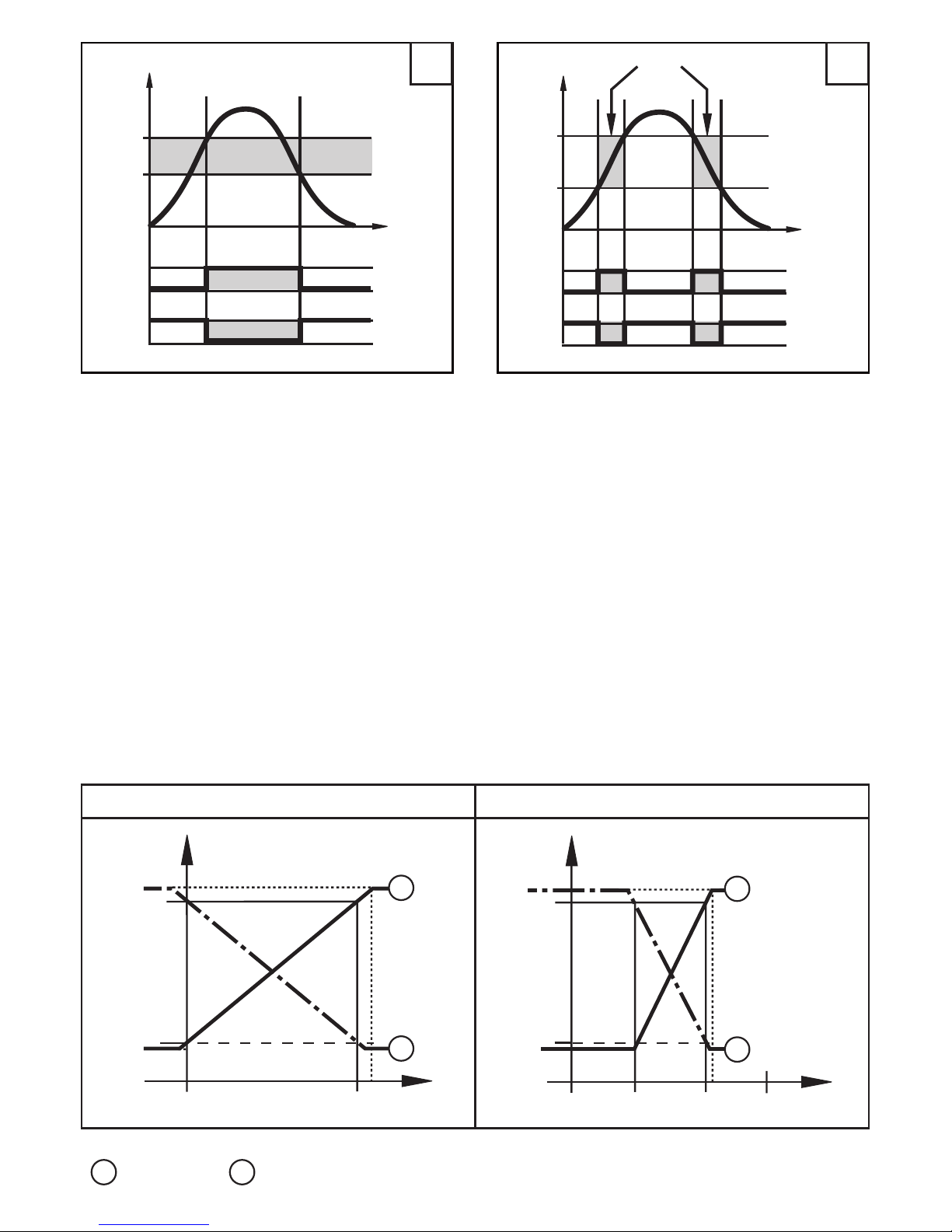
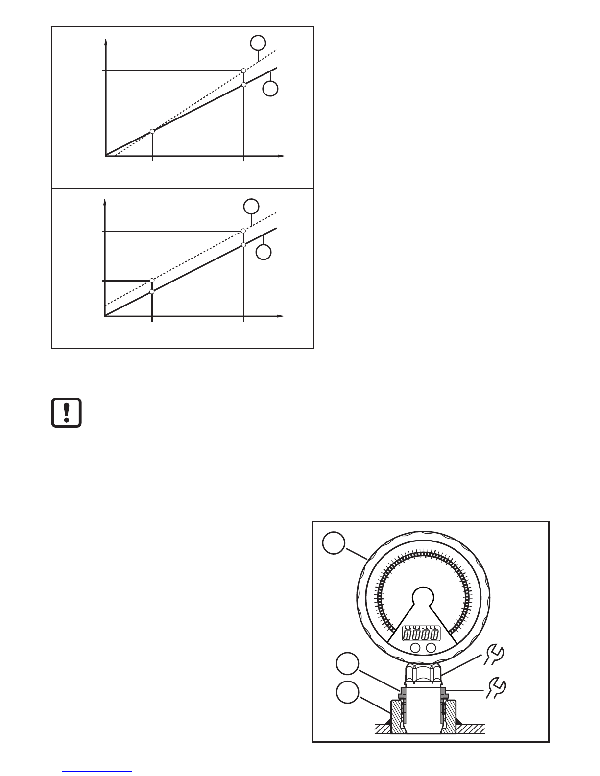
4.4 Customer-specific calibration
The customer-specific calibration changes the curve of measured values compared to the real measured values (shifting / change of the gradient; → 9�4�6
[CAL])�
• Two calibration points can be defined (CP1, CP2)� The two points are inde-
pendent of each other� They must be within the measuring range and not in the
extended display range�
• The zero point calibration [COF] influences the calibration of the curve of mea-
sured values� Recommendation: set [COF] to 0 (→ 9�4�1 [COF]), then calibrate
the curve of measured values�
After a change the calibration can be reset to factory setting (→ 9�5�2 [rES])�
• P = measured pressure;
P‘ = modified measured value
• CP1 = calibration point 1;
CP1‘ = modified measured value for
CP1
• CP2 = calibration point 2;
1 = curve of measured values at factory
setting
• 2 = curve of measured values after
calibration
Page 8
8
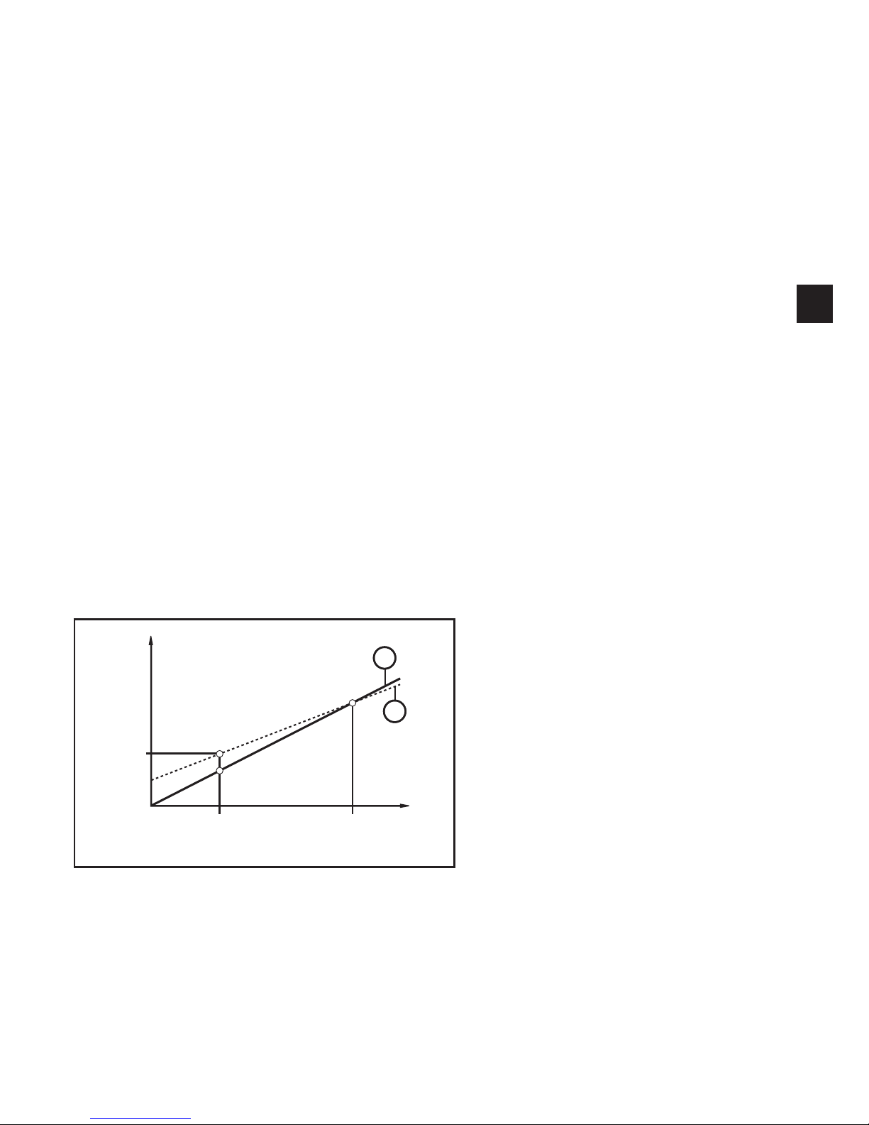
• P = measured pressure;
P‘ = modified measured value
• CP1 = calibration point 1;
CP2 = calibration point 2;
CP2‘ = modified measured value for
CP2
• 1 = curve of measured values at factory setting
• 2 = curve of measured values after
calibration
• P = measured pressure;
P‘ = modified measured value
• CP1 = calibration point 1;
CP1‘ = modified measured value for CP1
• CP2 = calibration point 2;
CP2‘ = modified measured value for CP2
• 1 = curve of measured values at factory setting
• 2 = curve of measured values after
calibration
5 Installation
Before installing and removing the unit: make sure that no pressure is applied to the system� Note: If 0% is displayed and no pointer is visible, this
does not mean that no pressure is applied to the system!
The unit must only be installed in a process connection for G1 sealing
cones (e�g� ifm welding adapter, order no� E30013)�
Installation in a process connection for a G1 sealing cones
► Insert the unit (A) into the process
connection (C), push the threaded
sleeve (B) towards the internal
thread of the process connection
and lightly screw it in�
► Orientate the unit, tighten the
threaded sleeve (B) with a spanner
and ensure that the unit is correctly
oriented while doing so�
Tightening torque 20 Nm��
24
34
A
B
C
Page 9

9
UK
Use in hygienic areas to EHEDG
► Make sure that the sensors are integrated into the system in accordance with
EHEDG�
After installation the analogue display can be rotated / adapted to the installation position� Use gloves to do so�
6 Electrical connection
The unit must be connected by a qualified electrician�
The national and international regulations for the installation of electrical
equipment must be adhered to�
Voltage supply according to EN 50178, SELV, PELV�
► Disconnect power�
► Connect the unit as follows:
OUT1 positive switching OUT1 negative switching
Pin 1 Ub+
Pin 3 Ub-
Pin 4 (OUT1) • Binary switching output pressure monitoring
Pin 2 (OUT2) • Analogue output for system pressure
Core colours of ifm sockets:
1 = BN (brown), 2 = WH (white), 3 = BU (blue), 4 = BK (black)
Page 10

10
7 Operating and display elements
Mode/
Enter
Set
1
2
3
4
5
6
1: Analogue display
- Display of the current system pressure in bar and PSI or mbar and inH2O�
2: LED ring
- Display of set point and reset point�
- Trend display: rising pressure (5 LEDs below the pointer) / falling pressure (5 LEDs
above the pointer)�
- Maximum value memory or minimum value memory�
3: Indicator LEDs
- LED 1 = system pressure of the digital display in bar�
- LED 2 = system pressure of the digital display in mbar�
- LED 3 = system pressure of the digital display in PSI�
- LED 4 = system pressure of the digital display in inH2O�
- LED 6 = system pressure in % of the scaling (range ASP to AEP) or COF value in %�
- LEDs 5, 7 = not used�
- LED 8 = switching status OUT1 (lights if output 1 is switched)
4: Alphanumeric display, 4 digits
- Display of the current system pressure�
- Display of the parameters and parameter values�
5: Touch button Set*
- Setting of the parameter values (continuously by touching permanently; step by step by
touching briefly several times)�
Page 11

11
UK
6: Touch button Mode/Enter*
- Selection of the parameters and acknowledgement of the parameter values�
* The two touch buttons are activated simply by touching / deactivated by releasing the
touch button�
The touch button must be completely covered to be activated�
Slow covering (e�g� liquid flows over the display) does not activate the touch button�
8 Menu
8.1 Menu structure: main menu
1: Change to menu level 2 (extended functions)
Page 12

12
8.2 Explanation of the main menu
SP1/rP1 Upper / lower limit value for system pressure at which OUT1 switches�
OU1 Output function for OUT1:
• Switching signal for the pressure limit values: hysteresis function [H ��] or
window function [F ��], either normally open [� no] or normally closed [� nc]�
OU2 Output function for OUT2:
• Analogue signal for the current system pressure: 4���20 mA [I], 20���4 mA
[InEG]�
tCOF Teach zero-point calibration�
tASP Teach analogue start point for system pressure: set measured value at which
4 mA is provided (20 mA if [OU2] = [InEG])�
tAEP Teach analogue end point for system pressure: set measured value at which
20 mA is provided (4 mA if [OU2] = [InEG])�
EF Extended functions / opening of menu level 2�
Page 13

13
UK
8.3 Menu structure: level 2 (extended functions)
1: Change to the main menu
Page 14

14
8.4 Explanation of the menu level 2
Uni Standard unit of measurement for system pressure�
SELd
Display mode:
• Pressure in the unit set in [Uni]�
• Pressure in % of the set scaling of the analogue output�
ASP Analogue start point for system pressure: measured value at which 4 mA is
provided (20 mA if [OU2] = [InEG])�
AEP Analogue end point for system pressure: measured value at which 20 mA is
provided (4 mA if [OU2] = [InEG])�
HI Maximum value memory for system pressure�
LO Minimum value memory for system pressure�
COF Zero-point calibration�
dS1 Switch-on delay for OUT1�
dr1 Switch-off delay for OUT1�
P-n Switching logic for OUT1: pnp or npn�
dAP Damping for switching outputs and display�
dAA Damping for analogue output (OUT2)�
diS Update rate and orientation of the display�
LED Setting for the LED ring�
CAL Calibration function (setting the curve of measured values)�
CP1 Calibration point 1
CP2 Calibration point 2
rES Restore factory settings�
Page 15

15
UK
9 Parameter setting
During parameter setting the unit remains in the operating mode� It continues its
monitoring function with the existing parameters until the parameter setting has
been completed�
9.1 General parameter setting
3 steps must be taken for each parameter setting:
1
Select parameter
► Touch [Mode/Enter] until the re-
quested parameter is displayed.
Mode/
Enter
Set
2
Set parameter value
► Touch [Set] and keep it touched�
> Current setting value of the param-
eter flashes for 5 s�
> After 5 s: setting value is changed:
step by step by touching briefly
several times or continuously by
touching permanently�
Mode/
Enter
Set
Numerical values are incremented continuously� To reduce the value: let the display
move to the maximum setting value� Then the cycle starts again at the minimum
setting value�
3
Acknowledge parameter value
► Touch [Mode/Enter] briefly�
> The parameter is displayed again�
The new setting value is saved�
Mode/
Enter
Set
Set other parameters
► Start again with step 1�
Finish parameter setting
► Touch [Mode/Enter] several times until the current measured value is displayed or wait
for 15
s�
> The unit returns to the operating mode�
• Timeout:
If no touch button is activated for 15 s during parameter setting, the unit returns to the
operating mode with unchanged values�
Page 16

16
• Change from menu level 1 to menu level 2:
► Touch [Mode/Enter] until [EF] is
displayed�
Mode/
Enter
Set
► Touch [Set] briefly�
> The first parameter of the submenu is
displayed (here: [Uni])�
If the menu level 2 is protected by an access code, "Cod1" flashes in the display�
► Touch [Set] and keep it touched until
the valid code no� appears�
► Touch [Mode/Enter] briefly�
On delivery by ifm electronic: no access
restriction�
Mode/
Enter
Set
• Locking / unlocking
The unit can be locked electronically to prevent an unintentional operation�
► Make sure that the unit is in the normal operating mode�
► Touch [Set],
► additionally touch [Mode/Enter] and keep both buttons touched for 10 s�
> The LED for the current unit of measurement flashes, the current system pressure
continues to be displayed� After 10 s the display goes out for approx� 1 s�
► Release [Mode/Enter] and [Set] again� Both buttons must be released within 4 s� If
this does not happen, the unit remains unlocked�
> [Loc] is displayed, the unit is locked� �
During operation the indicator LED for the display unit (→ chapter 7) is flashing if you
try to open the menu�
For unlocking:
► Make sure that the unit is in the normal operating mode�
► Touch [Set],
► additionally touch [Mode/Enter] and keep both buttons touched for 10 s�
> The LED for the current unit of measurement flashes, the current system pressure
continues to be displayed� After 10 s the display goes out for approx� 1 s�
► Release [Mode/Enter] and [Set] again� Both buttons must be released within 4 s� If
this does not happen, the unit remains unlocked�
> [uLoc] is displayed, the unit is unlocked�
On delivery: unlocked�
Page 17

17
UK
9.2 Configuration of the digital display (optional)
► Select [Uni] and set the unit of measurement:
- [bAr], [mbAr], [PSI], [inHO]�
► Select [SELd] and set type of indication:
- [P]: system pressure in the unit set in Uni�
- [P%]: system pressure in % of the set scaling of the analogue output;
the following applies: 0% = ASP value / 100% = AEP value�
Note: display “0%” does not mean that no pressure is applied to the system�
► Select [diS] and set the update rate of the display:
- [d1]: update of the measured values every 50 ms�
- [d2]: update of the measured values every 200 ms�
- [d3]: update of the measured values every 600 ms�
- [OFF] = The measured value display is deactivated in the Run mode�
Touching one of the buttons indicates the current measured value for
15 s� Touching the [Mode/Enter] button again activates the display
mode� The indicator LEDs remain active even if the display is deactivated�
► Select [LED] and set the display function for the digital display and LED
ring:
- [SPRP]: The LED ring indicates set point and reset point�
- [LO]: The LED ring indicates the saved minimum value for the system
pressure�
- [HI]: The LED ring indicates the saved maximum value for the system
pressure�
- [Ph]: Display of pulsating signals and pressure peaks:
- In case of quick pressure changes (quickly pulsating signals) the
digital display and LED ring indicate the minimum value and the
maximum value�
- In case of one-time short pressure peaks the digital display and LED
ring show the indication for a longer time�
- [Pdir]: The LED ring indicates the trend of the pressure changes (5
LEDs below the pointer for rising pressure; 5 LEDs above the pointer
for falling pressure)�
A damping set with dAP or dAA also has an effect on this display�
Page 18

18
9.3 Set output signals
9.3.1 Set output functions
► Select [OU1] and set the switching function:
- [Hno] = hysteresis function/NO�
- [Hnc] = hysteresis function/NC�
- [Fno] = window function/NO�
- [Fnc] = window function/NC�
► Select [OU2 ] and set the analogue function:
- [I] = current signal proportional to pressure 4…20 mA�
- [InEG] = current signal proportional to pressure 20…4 mA�
9.3.2 Set switching limits
► Select [SP1] and set the value at which the output switches�
► Select [rP1] and set the value at which OUT1 switches off�
rP1 is always smaller than SP1� The unit only accepts values which are
lower than SP1�
9.3.3 Scale analogue value for OUT2
► Set the minimum pressure requested in the system�
► Touch [Mode/Enter] until [tASP] appears�
► Touch [Set] and keep it touched�
> Current setting value flashes�
► Release [Set] when the display stops flashing�
> New setting value is displayed�
► Touch [Mode/Enter] briefly�
> The current system pressure is defined as start value for the analogue
signal�
► Set the maximum pressure requested in the system�
► Touch [Mode/Enter] until [tAEP] appears�
► Touch [Set] and keep it touched�
> Current setting value flashes�
► Release [Set] when the display stops flashing�
> New setting value is displayed�
► Touch [Mode/Enter] briefly�
> The current system pressure is defined as end value for the analogue
signal�
ASP / AEP can only be set automatically within defined limits (→ 12�1 Setting ranges)�
If automatic setting is carried out at an invalid pressure value, [UL] or [OL] is displayed�
After acknowledgement by [Mode/Enter] [Err] flashes, the ASP value / AEP value is not
changed�
Page 19

19
UK
As an alternative:
► Select [ASP] and set the measured value at which 4 mA is provided
(20 mA at [OU2] = [InEG])�
► Select [AEP] and set the measured value at which 20 mA is provided
(4 mA at [OU2] = [InEG])�
Minimum distance between ASP and AEP = 25 % of the final value of the
measuring range (turn-down 1:4)�
9.4 User settings (optional)
9.4.1 Carry out zero point calibration
► Select [COF] and set a value between -5% and 5% of the final value of
the measuring range� The internal measured value "0" is shifted by this
value�
As an alternative: automatic adjustment of the offset in the range 0 bar ± 5
%�
► Make sure that no pressure is applied to the system�
► Touch [Mode/Enter] until [tCOF] appears�
► Touch [Set] and keep it touched�
> The current offset value (in %) flashes briefly�
> The current system pressure is displayed�
► Release [Set]�
► Touch [Mode/Enter] briefly (= to confirm the new offset value)�
9.4.2 Set delay time for OUT1
[dS1] = switch-on delay / [dr1] = switch-off delay�
► Select [dS1] or [dr1] and set a value between 0�1 and 50 s (at 0�0 the
delay time is not active)�
9.4.3 Set switching logic for OUT1
► Select [P-n] and set [PnP] or [nPn]�
9.4.4 Set damping for the switching signal
► Select [dAP] and set a value between 0�01 and 30 s�
dAP value = response time between pressure change and change of the
switching status in seconds�
[dAP] influences the switching frequency: f
max
= 1 ÷ 2dAP�
[dAP] also has an effect on the display�
Page 20

20
9.4.5 Set damping for the analogue signal
► Select [dAA] and set a value between 0�01 and 30 s�
dAA value = response time between pressure change and change of the
analogue signal in seconds�
9.4.6 Calibrate curve of measured values
If the unit is to adopt the settings for the calibration points, the following conditions must be
adhered to:
- CP1 and CP2 must be within the measuring range (i�e� between ASP and AEP)�
- CP1 and CP2 must not be in the extended display range�
- Minimum distance between the calibration points CP1 and CP2 = 5 % of the final value of
the measuring range�
- Maximum correction value = ± 2 % of the final value of the measuring range�
► Set a defined reference pressure between ASP and AEP in the system�
► Select [CAL]�
► Touch [Set] briefly�
> [CP1] is displayed�
► Touch [Set] for 5 s�
> The pressure measured by the unit is displayed�
► Touch [Set] until the set reference pressure is indicated (measured
pressure = reference pressure) or the corresponding analogue signal is
provided to OUT2�
► Touch [Mode/Enter] briefly�
> [CP1] is displayed�
► Touch [Mode/Enter] briefly�
> [CP2] is displayed�
Continue with a) or b)�
a) Finish calibration:
► Touch [Mode/Enter] briefly�
> [CAL] is displayed�
b) Change a 2nd point on the curve of measured values:
► Set a second defined reference pressure in the system�
► Touch [Set] for 5 s�
> The pressure measured by the unit is displayed�
► Touch [Set] until the set reference pressure is indicated (measured
pressure = reference pressure) or the corresponding analogue signal is
provided to OUT2�
► Touch [Mode/Enter] briefly�
> [CP2] is displayed�
► Touch [Mode/Enter] briefly�
> [CAL] is displayed, the process is finished�
Page 21

21
UK
9.5 Service functions
9.5.1 Read min/max values for system pressure
► Select [HI] or [LO] and touch [Set] briefly�
[HI] = maximum value, [LO] = minimum value�
Delete memory:
► Select [HI] or [LO]�
► Touch [Set] and keep it touched until [----] is displayed�
► Touch [Mode/Enter] briefly�
9.5.2 Reset all parameters to factory setting
► Select [rES]�
► Touch [Set] and keep it touched until [----] is displayed�
► Touch [Mode/Enter] briefly�
It is recommended to take down your own settings in the table before carrying out a reset (→13 Factory setting)�
10 Operation
After power on, the unit is in the Run mode (= normal operating mode)� It carries
out its measurement and evaluation functions and provides output signals according to the set parameters�
Operating indicators → 7 Operating and display elements�
10.1 Read set parameters
► Touch [Mode/Enter] until the requested parameter is displayed�
► Touch [Set] briefly�
> The unit displays the corresponding parameter value for about 15 s� After
another 15 s it returns to the Run mode�
10.2 Error indications
[OL] Overload pressure (measuring range exceeded)�
[UL] Underload pressure (below measuring range)�
[SC1] Short circuit in OUT1� The output is switched off as long as the short circuit
persists�
[Err] Flashing: internal error, invalid entry�
The messages SC1 and Err are displayed even if the display is switched off�
Page 22

22
11 Scale drawing
24
34
3
153
27
100
2
1
G1
57
60,5
M12 x1
Dimensions in mm
1: analogue display
2: digital display
3: touch button (programming button)
Page 23

23
UK
12 Technical data
Operating voltage [V] ������������������������������������������������������������������������������������������� 18���32 DC
Current consumption [mA] ���������������������������������������������������������������������������������� < 70 (24 V)
Current rating [mA] ��������������������������������������������������������������������������������������������������������� 250
Short-circuit protection; reverse polarity protection / overload protection, integrated
watchdog
Voltage drop [V] �������������������������������������������������������������������������������������������������������������� < 2
Power-on delay time [s] ����������������������������������������������������������������������������������������������������� 6
Min� response time switching output [ms] ������������������������������������������������������������������������ 10
Switching frequency [Hz] ��������������������������������������������������������������������������������������������������50
Analogue output ������������������������������������������������������������������������������� 4���20 mA / 20���4 mA
Max� load [Ω] ������������������������������������������������������������������������������������������������� (Ub - 10) x 50
Step response time analogue output [ms] ����������������������������������������������������������������������� 25
Accuracy / deviations (in % of the span)
1)
PG289x PG2889
Switch point accuracy < ± 0�2 < ± 0�5
Switch point accuracy in the extended display range 1�5 1�5
Characteristics deviation (linearity, incl� hysteresis and repeat-
ability)
2)
< ± 0�2 < ± 0�5
Characteristics deviation in the extended display range 1�5 1�5
Linearity < ± 0�15 < ± 0�25
Hysteresis < ± 0�15 < ± 0�2
Repeatability (in case of temperature fluctuations < 10 K) < ± 0�1 < ± 0�1
Long-term stability (in % of the span per year) < ± 0�1 < ± 0�1
Temperature coefficients (TEMPCO) in the compensated temperature range 0 ���70°C (in
% of the span per 10 K)
PG289x PG2889
Greatest TEMPCO of the zero point < ± 0�05 < ± 0�1
Greatest TEMPCO of the span < ± 0�15 < ± 0�2
Page 24

24
Materials (wetted parts)
�������������������������������� stainless steel 316L / 1�4435, surface characteristics: Ra < 0�4 / Rz 4
ceramics (99�9 % Al2O3); PTFE
Housing materials ���������������������������� stainless steel 316L / 1�4404; PA; FPM (Viton); PTFE;
viewing glass: laminated safety glass 4 mm
Protection rating ��������������������������������������������������������������������������������������������IP 67 / IP 69K
Protection class ������������������������������������������������������������������������������������������������������������������III
Insulation resistance [MΩ] �������������������������������������������������������������������������> 100 (500 V DC)
Shock resistance [g] ���������������������������������������������������������������� 50 (DIN IEC 68-2-27, 11 ms)
Vibration resistance [g] �������������������������������������������������� 20 ( DIN IEC 68-2-6, 10 - 2000 Hz)
Switching cycles min� ������������������������������������������������������������������������������������������ 100 million
Ambient temperature [°C] ��������������������������������������������������������������������������������������� -25 ��� 80
Medium temperature [°C] ��������������������������������������������������������������� -25���125 (145 max� 1 h)
Storage temperature [°C]���������������������������������������������������������������������������������������� -40���100
EMC EN 61000-4-2 ESD: ��������������������������������������������������������������������������������������� 4 / 8 kV
EN 61000-4-3 HF radiated: ���������������������������������������������������������������������������� 10 V/m
EN 61000-4-4 Burst: ������������������������������������������������������������������������������������������� 2 kV
EN 61000-4-5 Surge: ���������������������������������������������������������������������������������� 0�5 / 1 kV
EN 61000-4-6 HF conducted: ���������������������������������������������������������������������������� 10 V
1)
1) All indications are referred to a turn-down of 1:1
2)
Limit value setting to DIN 16086
Page 25

25
UK
13 Setting ranges
SP1 rP1 ASP AEP
ΔP
min max min max min max min max
PG2889
mbar -4�8 160�0 -5�0 159�8 -5�0 135�0 20�0 160�0 0�1
inH2O -1�95 64�25 -2�05 64�15 -2�00 54�20 8�05 64�25 0�05
PG2893
bar -0�96 40�00 -1�00 39�96 -1�00 33�76 5�24 40�00 0�02
PSI -13�8 579�9 -14�4 579�3 -14�4 489�3 75�9 579�9 0�3
PG2894
bar -0�98 16�00 -1�00 15�98 -1�00 13�50 1�50 16�00 0�01
PSI -14�3 232�0 -14�5 231�8 -14�5 195�7 21�8 232�0 0�1
PG2895
bar -0�990 6�400 -1�000 6�390 -1�000 5�400 0�000 6�400 0�005
PSI -14�35 92�80 -14�50 92�70 -14�50 78�30 0�00 92�80 0�05
PG2896
bar -0�120 4�000 -0�124 3�996 -0�124 3�370 0�500 4�000 0�002
PSI -1�74 58�02 -1�80 57�96 -1�80 48�87 7�26 58�02 0�03
PG2897
bar -0�048 1�600 -0�050 1�598 -0�050 1�350 0�200 1�600 0�001
PSI -0�69 23�22 -0�73 23�19 -0�73 19�59 2�91 23�22 0�01
PG2898
mbar -12�0 400�0 -12�4 399�6 -12�4 337�6 50�0 400�0 0�2
inH2O -4�8 160�6 -5�0 160�4 -5�0 135�5 20�1 160�6 0�1
PG2899
bar -0�998 1�600 -1�000 1�598 -1�000 1�100 -0�500 1�600 0�001
PSI -14�45 23�20 -14�50 23�18 -14�50 15�95 -7�25 23�20 0�02
ΔP = step increment
Page 26

26
14 Factory setting
Factory setting User setting
SP1 25.0 % VMR*
rP1 24.9 % VMR*
OU1 Hno
OU2 I
COF / tCOF 0.0
ASP / tASP 0% VMR*
AEP / tAEP 100% VMR*
Uni bAr / mbAr
SELd P
dS1 0.0
dr1 0.0
P-n pnp
dAP 0.06
dAA 0.03
dis d2
LED SPRP
CP1 0.00
CP2 0.00
* = the indicated percentage of the final value of the measuring range (VMR) of the corresponding sensor is set�
More information at www�ifm�com
 Loading...