

Page 1

Bedienungsanleitung
Operating instructions
Notice utilisateurs
Combi-Drucksensor
Combined pressure
sensor
Capteur de pression
combiné
PN3/PE3
Sachnr. 701589/01 07/01
DEUTSCHENGLISHFRANÇAIS
R
Page 2

2
DEUTSCH
Inhalt
Sicherheitshinweise . . . . . . . . . . . . . . . . . . . . . Seite 5
Bedien- und Anzeigeelemente . . . . . . . . . . . . . . Seite 5
1. Bestimmungsgemäße Verwendung . . . . . . . . . . Seite 6
2. Betriebsarten . . . . . . . . . . . . . . . . . . . . . . . . . . Seite 7
3. Einstellbare Parameter . . . . . . . . . . . . . . . . . . . . Seite 9
4. Montage . . . . . . . . . . . . . . . . . . . . . . . . . . . . Seite 10
5. Elektrischer Anschluß . . . . . . . . . . . . . . . . . . . Seite 10
6. Programmieren . . . . . . . . . . . . . . . . . . . . . . . . Seite 11
7. Inbetriebnahme / Betrieb . . . . . . . . . . . . . . . . . Seite 12
8. Maßzeichnung . . . . . . . . . . . . . . . . . . . . . . . .Seite 12
9. Technische Daten . . . . . . . . . . . . . . . . . . . . . . Seite 13
ENGLISH
Contents
Safety instructions . . . . . . . . . . . . . . . . . . . . . page 14
Controls and visual indication . . . . . . . . . . . . . page 14
1. Function and features . . . . . . . . . . . . . . . . . . . page 15
2. Operating modes . . . . . . . . . . . . . . . . . . . . . . page 17
3. Adjustable parameters . . . . . . . . . . . . . . . . . . page 18
4. Installation . . . . . . . . . . . . . . . . . . . . . . . . . . . page 19
5. Electrical connection . . . . . . . . . . . . . . . . . . . . page 19
6. Programming . . . . . . . . . . . . . . . . . . . . . . . . . page 20
7. Installation and set-up / operation . . . . . . . . . . page 21
8. Scale drawing . . . . . . . . . . . . . . . . . . . . . . . . .page 21
9. Technical data . . . . . . . . . . . . . . . . . . . . . . . . page 22
FRANÇAIS
Contenu
Remarque sur la sécurité . . . . . . . . . . . . . . . . . page 24
Eléments de service et d’indication . . . . . . . . . page 24
1. Fonctionnement et caractéristiques . . . . . . . . . page 25
2. Modes de fonctionnement . . . . . . . . . . . . . . . page 27
3. Paramètres réglables . . . . . . . . . . . . . . . . . . . . page 28
4. Montage . . . . . . . . . . . . . . . . . . . . . . . . . . . . page 29
5. Raccordement électrique . . . . . . . . . . . . . . . . . page 29
6. Programmation . . . . . . . . . . . . . . . . . . . . . . . page 30
7. Mise en service / Fonctionnement . . . . . . . . . . page 31
8. Dimensions . . . . . . . . . . . . . . . . . . . . . . . . . . .page 31
9. Données techniques . . . . . . . . . . . . . . . . . . . . page 32
Page 3
PN3/PE3 Sachnr. 701589/01 3
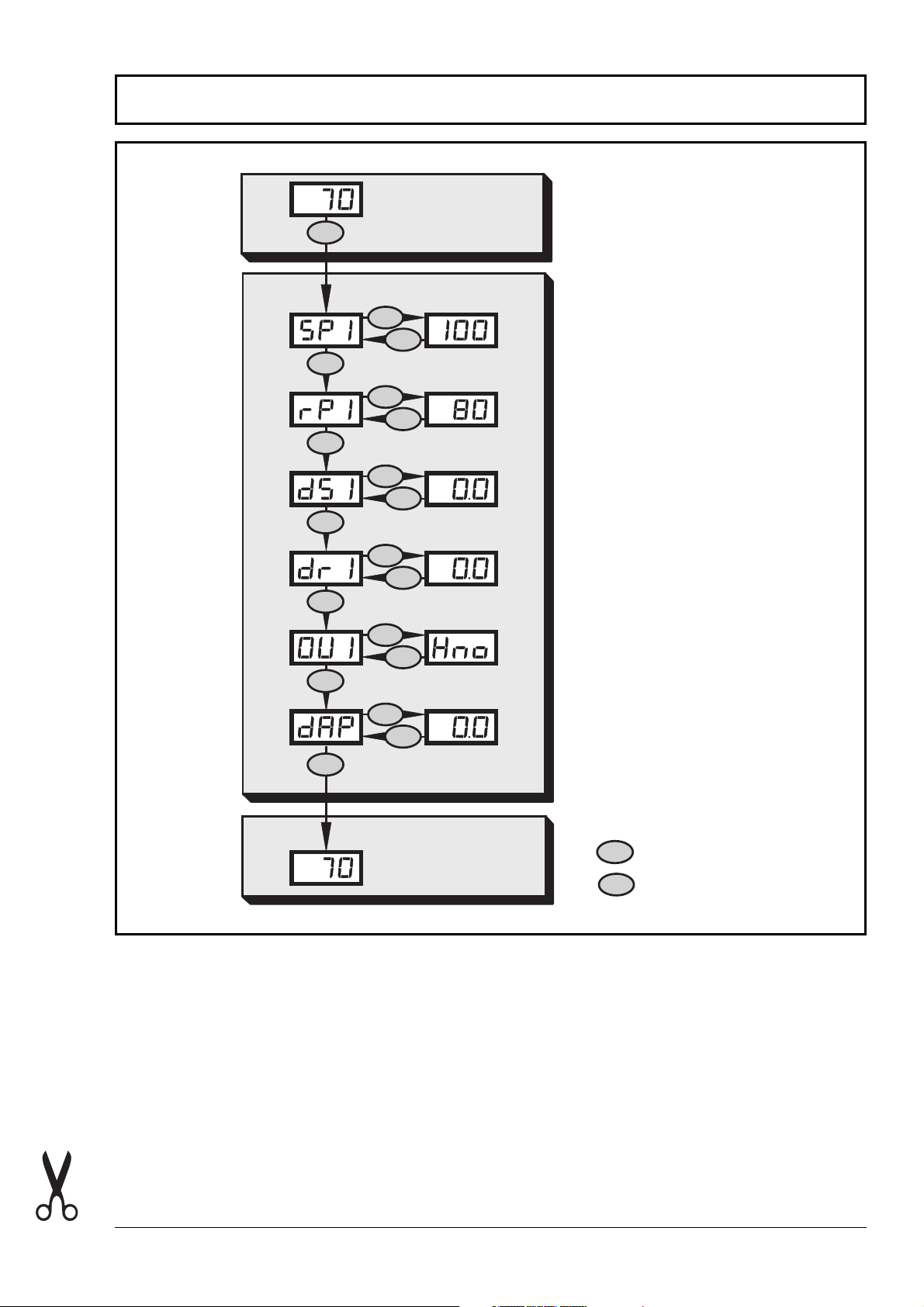
Menü-Übersicht / Menu structure / Structure du menu
M
M
M
M
M
M
RUN
S
M
S
M
S
M
S
M
S
M
M
S
M
RUN
= Mode/Enter
M
= Set
S
Page 4
4
*Wert verringern: Lassen Sie die Anzeige bis zum maximalen Einstellwert
laufen. Danach beginnt der Durchlauf wieder beim minimalen
Einstellwert.
*Decrease the value: Let the display of the parameter value move to the
maximum setting value. Then the cycle starts again at the minimum setting value.
*Réduire la valeur du paramètre: Laisser l'affichage de la valeur du
paramètre aller jusqu'à la valeur de réglage maximum. Ensuite le cycle
recommence à la valeur de réglage minimum.
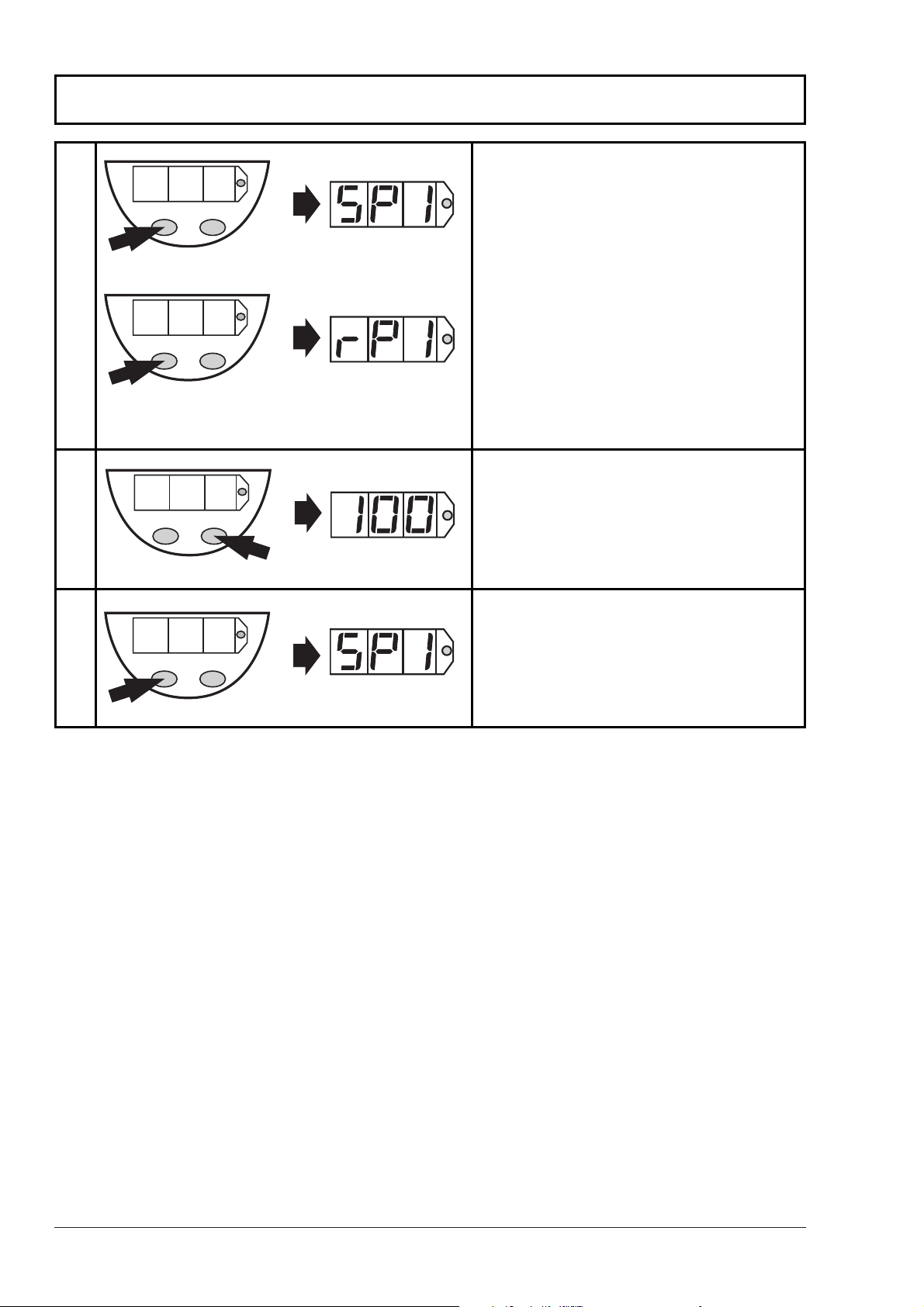
Programmieren / Programming / Programmation
PN3/PE3Sachnr. 701589/01
1
Mode/Enter
Set
Mode/Enter
Set
Mode/Enter
Set
Mode/Enter
Set
2
3
1 x
2 x
...
> 5s
1 x
Parameter aufrufen
Select parameters
Sélectionner les paramètres
Werte einstellen*
Set Values*
Régler la valeurs*
Werte bestätigen
Acknowledgement of values
Confirmer la valeur
Page 5
5
DEUTSCH
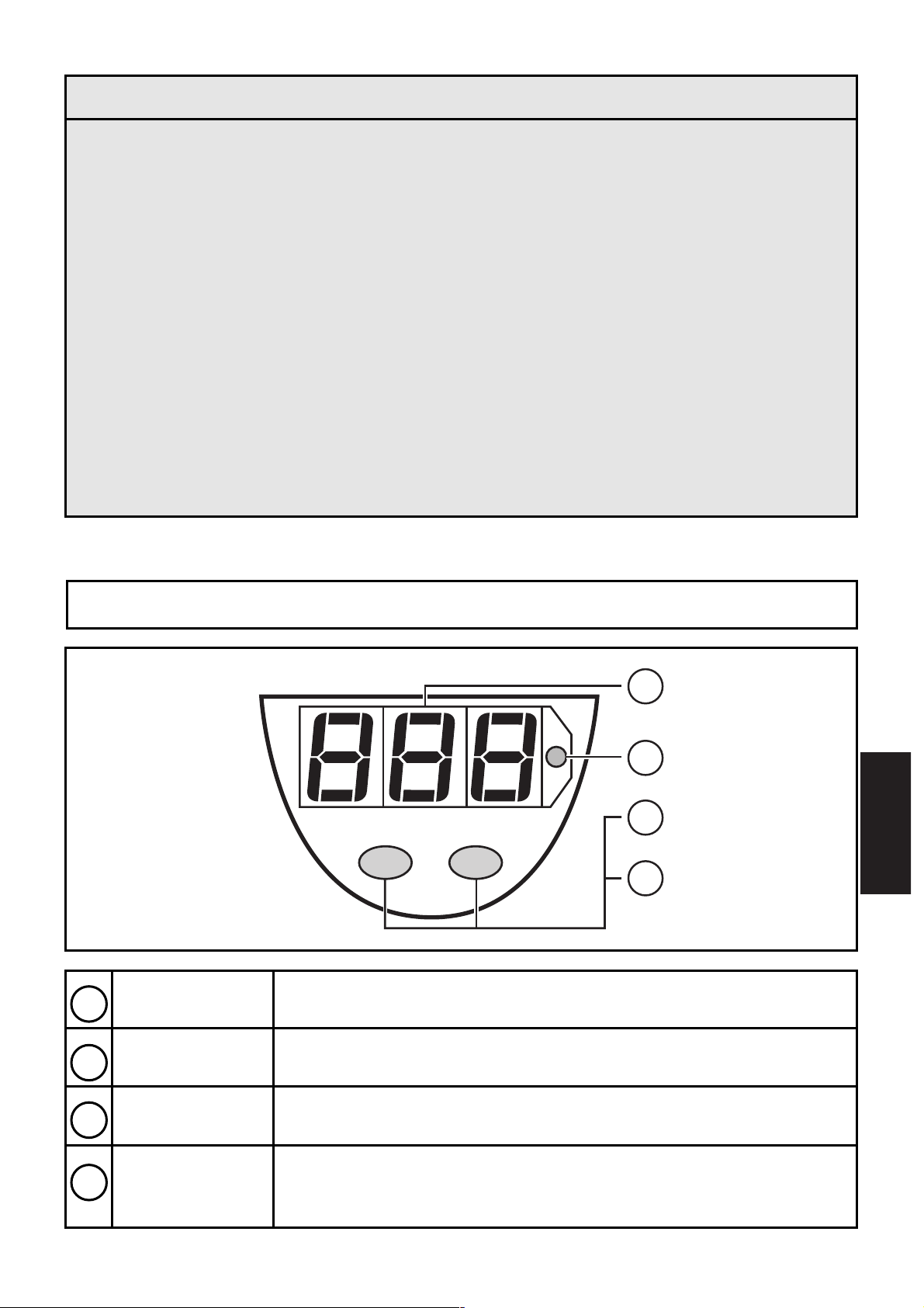
Bedien- und Anzeigeelemente
7-Segment-
Anzeige
Anzeige des Systemdrucks,
Anzeige der Parameter und Parameterwerte
LED rot
Anzeige des Schaltzustands; leuchtet,
wenn der Ausgang durchgeschaltet ist
Taste
Mode / Enter
Anwahl der Parameter und Bestätigen der
Parameterwerte
Taste
Set
Einstellen der Parameterwerte
(kontinuierlich durch Dauerdruck;
schrittweise durch Einzeldruck)
1
2
3
4
Sicherheitshinweise
Lesen Sie vor der Inbetriebnahme des Gerätes die
Produktbeschreibung. Vergewissern Sie sich, daß sich das
Produkt uneingeschränkt für die betreffende Applikationen
eignet.
Die Mißachtung von Anwendungshinweisen oder technischen
Angaben kann zu Sach- und/oder Personenschäden führen.
Prüfen Sie in allen Applikationen die Verträglichkeit der
Produktwerkstoffe (s. Technische Daten) mit den zu messenden Druckmedien.
Bei gasförmigen Druckmedien ist der Einsatzbereich generell
auf max. 25bar begrenzt.
Mode/Enter Set
[bar]
1
2
3
4
Page 6
1. Bestimmungsgemäße Verwendung
• Der Drucksensor erfaßt den Systemdruck,
• zeigt ihn durch ein Display an (Anzeigebereich 1% ... 105% des
Meßbereichsendwerts)
• und erzeugt 2 Ausgangssignale entsprechend der eingestellten
Ausgangskonfiguration.
Einsatzbereich
Druckart: Relativdruck
Vermeiden Sie statische und dynamische Überdrücke, die den
angegebenen Überlastdruck überschreiten.
Bei gasförmigen Druckmedien ist der Einsatzbereich generell auf
max. 25bar begrenzt.
Schon bei kurzzeitiger Überschreitung des Berstdrucks kann das
Gerät zerstört werden (Verletzungsgefahr)!
Anzeige des aktuellen Systemdrucks ab 1% des
Meßbereichsendwerts. Anzeige “0” bedeutet nicht, daß die
Anlage druckfrei ist!
6
Berstdruck
Zulässiger
Überlastdruck
Meßbereich
Bestell-
nummer
PN3xx0/PE3xx0 0 ... 400 bar 600 bar 1000 bar
PN3xx1/PE3xx1 0 ... 250 bar 400 bar 850 bar
PN3xx2/PE3xx2 0 ... 100 bar 300 bar 650 bar
PN3xx3/PE3xx3 0 ... 25 bar 100 bar 350 bar
PN3xx4/PE3xx4 0 ... 10 bar 50 bar 150 bar
PN3xx6/PE3xx6 0 ... 2,5 bar 20 bar 50 bar
PN3xx7/PE3xx7 0 ... 1 bar 10 bar 30 bar
PN3x29/PE3x29 -1 ... 0 bar 10 bar 30 bar
Ausgang 1
Hysteresefunktion / Schließer (Hno)
Hysteresefunktion / Öffner (Hnc)
Fensterfunktion / Schließer (Fno)
Fensterfunktion / Öffner (Fnc)
Ausgang 2
Analog 4 ... 20 mA
Page 7
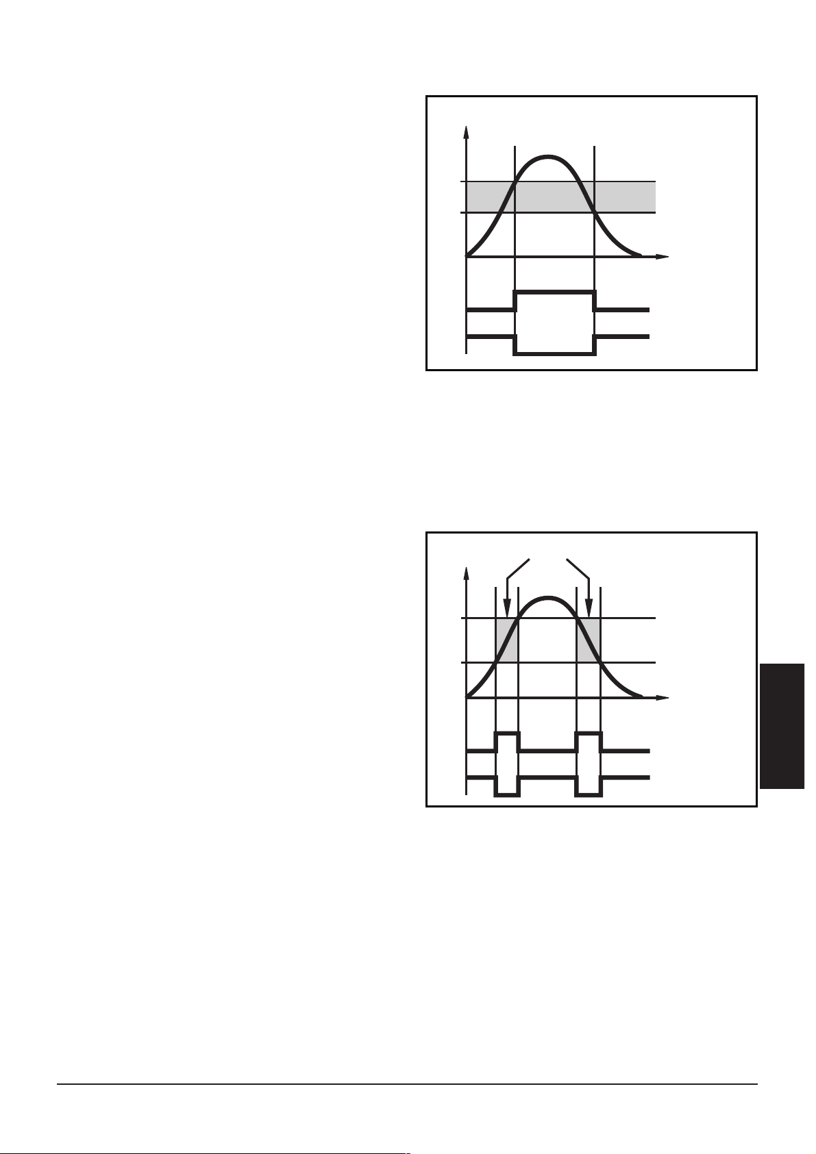
Hysteresefunktion:
Die Hysterese hält den
Schaltzustand des Ausgangs stabil, wenn der Systemdruck um
den Sollwert schwankt.
Bei steigendem Systemdruck
schaltet der Ausgang bei
Erreichen des Schaltpunkts (SP1);
fällt der Systemdruck wieder ab,
schaltet der Ausgang erst dann
zurück, wenn der Rückschaltpunkt (rP1) erreicht ist.
Die Hysterese ist einstellbar: Zuerst wird der Schaltpunkt festgelegt,
dann im gewünschten Abstand der Rückschaltpunkt.
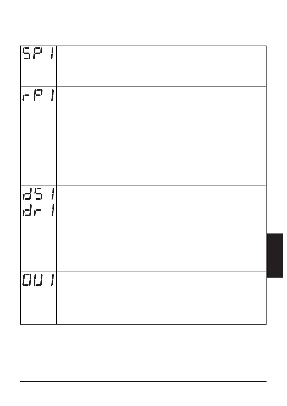
Fensterfunktion:
Die Fensterfunktion erlaubt die
Überwachung eines definierten
Gutbereichs.
Bewegt sich der Systemdruck
zwischen Schaltpunkt (SP1) und
und Rückschaltpunkt (rP1), ist
der Ausgang durchgeschaltet
(Fensterfunktion / Schließer) bzw.
geöffnet(Fensterfunktion/ Öffner).
Die Breite des Fensters ist einstellbar durch den Abstand von
SP1 zu rP1. SP1 = oberer Wert, rP1 = unterer Wert.
7
DEUTSCH
Hno
Hysterese
Hnc
Fno
Gutbereich
Fnc
P
SP
rP
1
0
t
1
0
P
SP
rP
1
0
1
0
t
Page 8

2. Betriebsarten
Run-Modus:
(Normaler Arbeitsbetrieb)
Nach dem Einschalten der Versorgungsspannung befindet sich das
Gerät im Run-Modus. Es führt seine Überwachungsfunktion aus,
schaltet den Transistorausgang entsprechend der eingestellten
Parameter und wandelt den aktuellen Systemdruck in ein analoges
Ausgangssignal um.
Das Display zeigt den aktuellen Systemdruck an, die rote LED signalisiert den Schaltzustand des Ausgangs.
Display-Modus:
(Anzeige der Parameter und der eingestellten Parameterwerte)
Das Gerät geht durch kurzen Druck auf die Taste “Mode/Enter” in den
Display-Modus. Intern verbleibt es im Arbeitsbetrieb. Unabhängig
davon können die eingestellten Parameterwerte abgelesen werden:
• Kurzer Druck auf die Taste “Mode/Enter” blättert durch die
Parameter.
• Kurzer Druck auf die Taste “Set” zeigt für ca. 5 s den zugehörigen
Parameterwert; danach geht das Gerät zurück in den Run-Modus.
Programmier-Modus:
(Einstellen der Parameterwerte)
Das Gerät geht in den Programmiermodus, wenn nach Anwahl eines
Parameters (Display-Modus) die Taste “Set” gedrückt wird, bis sich die
Anzeige des Parameterwerts ändert. Das Gerät verbleibt auch hier
intern im Arbeitsbetrieb. Es führt seine Überwachungsfunktionen mit
den bestehenden Parametern weiter aus, bis die Veränderung abgeschlossen ist.
Sie können den Parameterwert mit der Taste “Set” ändern und mit
der Taste “Mode/Enter” bestätigen. Das Gerät geht in den Run-Modus
zurück, wenn danach 5s lang keine Taste mehr gedrückt wird.
8
Page 9
3. Einstellbare Parameter
(Menüstruktur: siehe Seite 3)
9
DEUTSCH
Schaltpunkt: Oberer Grenzwert, bei dem der Ausgang seinen
Schaltzustand ändert.
• Einstellbereich: 1 ... 100% des Meßbereichsendwerts
• in Schritten von 0,5% des Meßbereichsendwerts
• Anzeige in bar
Verzögerungszeit für den Schaltausgang
dS1 = Einschaltverzögerung; dr1 = Ausschaltverzögerung
Der Ausgang ändert seinen Schaltzustand nicht sofort bei
Eintritt des Schaltereignisses, sondern erst nach Ablauf der
Verzögerungszeit. Besteht das Schaltereignis nach Ablauf der
Verzögerungszeit nicht mehr, ändert sich der Schaltzustand des
Ausgangs nicht.
• Einstellbereich: 0 - 0,2 - 0,4 ... 9,8 - 10 - 11 - ... - 49 - 50s
• in Schritten von 0,2 bzw 1s
• Anzeige in Sekunden
Schaltfunktion des Transistorausgangs
Es sind 4 Einstellungen wählbar:
Hno = Hysteresefunktion / normally open (Schließer)
Hnc = Hysteresefunktion / normally closed (Öffner)
Fno
= Fensterfunktion / normally open (Schließer)
Fnc
= Fensterfunktion / normally closed (Öffner)
Rückschaltpunkt: Unterer Grenzwert, bei dem der Ausgang
seinen Schaltzustand ändert.
• Einstellbereich: 0,5 ... 99,5% des Meßbereichsendwerts.
• in Schritten von 0,5% des Meßbereichsendwerts
• Anzeige in bar
rP1 ist stets kleiner als SP1. Es können nur Werte eingegeben
werden, die 0,5% unter dem Wert für SP1 liegen.
Bei Veränderung des Schaltpunkts wird der Rückschaltpunkt
mitgezogen (der Abstand zwischen SP1 und rP1 bleibt konstant).
Ist der Abstand größer als der neue Schaltpunkt, wird er
automatisch reduziert (rP1 wird auf den minimalen Einstellwert
gesetzt).
Page 10
4. Montage
Stellen Sie vor Ein- und Ausbau des Sensors sicher, daß die
Anlage druckfrei ist.
Befestigen Sie den Drucksensor an einem entsprechenden
Prozeßanschluß (s. Typaufkleber “Port Size”).
5. Elektrischer Anschluß
Das Gerät darf nur von einer Elektrofachkraft installiert werden.
Befolgen Sie die nationalen und internationalen Vorschriften zur
Errichtung elektrotechnischer Anlagen.
Spannungsversorgung nach EN50178, SELV, PELV.
Schalten Sie die Anlage spannungsfrei bevor Sie das Gerät
anschließen.
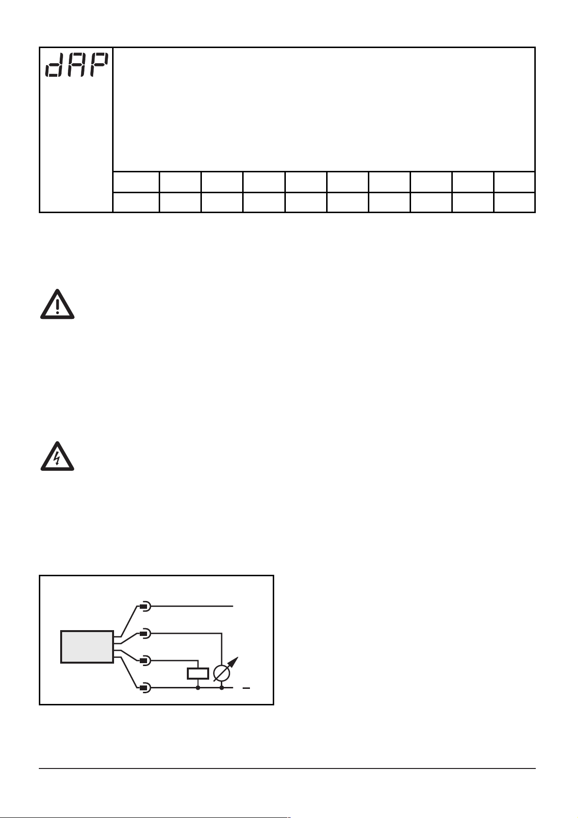
Anschlußbelegung:
10
Dämpfung für den Schaltausgang
Mit dieser Funktion lassen sich Druckspitzen von kurzer Dauer
oder hoher Frequenz ausfiltern.
dAP-Wert = Ansprechzeit zwischen Druckänderung und Änderung des Schaltzustands in ms.
• Einstellbar sind folgende feste Werte; diese Werte bestimmen
die Schaltfrequenz (f) des Ausgangs:
dAP
f [Hz]3170
6
80
10
50
17
30
30
16
60
8
12542502500
1
Adernfarben bei ifm-Kabeldosen:
1 = BN (braun), 2 = WH (weiß)
3 = BU (blau), 4 = BK (schwarz)
1
BN
2
WH
4
BK
3
BU
+
L
L
Page 11

6. Programmieren
Führen Sie zum Programmieren die folgenden Schritte durch:
Wird während des Einstellvorgangs 20s lang keine Taste gedrückt,
geht das Gerät mit unveränderten Werten in den Betriebsmodus
zurück.
Verriegeln / Entriegeln
Das Gerät läßt sich elektronisch verriegeln, so daß unbeabsichtigte
Fehleingaben verhindert werden: Drücken Sie im Run-Modus 10s lang
die beiden Programmiertasten. Sobald die Anzeige verlischt, ist das
Gerät verriegelt oder entriegelt.
Auslieferungszustand: Nicht verriegelt.
Bei verriegeltem Gerät erscheint kurzzeitig in der Anzeige, wenn
versucht wird, Parameterwerte zu ändern.
11
DEUTSCH
1
Mode/Enter
Set
Mode/Enter
Set
Mode/Enter
Set
Drücken Sie die Taste Mode/Enter,
bis der gewünschte Parameter
im Display erscheint.
Drücken Sie die Taste Set und
halten Sie sie gedrückt.
Der aktuelle Parameterwert wird
5s lang angezeigt,
danach wird er erhöht*
(schrittweise durch Einzeldruck
oder kontinuierlich durch
Festhalten der Taste).
Drücken Sie kurz die Taste
Mode/Enter (= Bestätigung).
Der Parameter wird erneut angezeigt; der neue Parameterwert
ist wirksam.
2
3
*Wert verringern: Lassen Sie die Anzeige bis zum maximalen Einstellwert
laufen. Danach beginnt der Durchlauf wieder beim minimalen Einstellwert.
Warten Sie 5s (das Gerät geht in den Betriebsmodus und
zeigt den aktuellen Meßwert),
oder beginnen Sie wieder mit Schritt 1,
um weitere Parameter zu programmieren.
Page 12

7. Inbetriebnahme / Betrieb
Prüfen Sie nach Montage, elektrischem Anschluß und Programmierung, ob das Gerät sicher funktioniert.
Störanzeigen während des Betriebs:
8. Maßzeichnung
12
7-Segment-Anzeige
Programmiertaste
Prozeßanschluß
= Überlastdruck
(Systemdruck > 110% des max. Nenndrucks).
(blinkend) = Kurzschluß im Schaltausgang;
der Ausgang ist abgeschaltet.
M12x1
34
91,5
48
M12x1
57,3
30
Page 13

9. Technische Daten
13
DEUTSCH
Betriebsspannung [V] . . . . . . . . . . . . . . . . . . . . . . . . . . . . . . . 20 ... 30 DC
Strombelastbarkeit [mA] . . . . . . . . . . . . . . . . . . . . . . . . . . . . . . . . . . . 250
Kurzschlußschutz, getaktet, verpolungssicher / überlastfest,
Watchdog integriert
Spannungsabfall [V] . . . . . . . . . . . . . . . . . . . . . . . . . . . . . . . . . . . . . . . < 2
Stromaufnahme [mA]. . . . . . . . . . . . . . . . . . . . . . . . . . . . . . . . . . . . . < 60
Analogausgang . . . . . . . . . . . . . . . . . . . . . . . . . . . . . . . . . . . . 4 ... 20 mA
Bürde [Ω] . . . . . . . . . . . . . . . . . . . . . . . . . . . . . . . . . . . . . . . . . . max. 500
Kennlinienabweichung[% vom Meßbereichsendwert]. . . . . . . . . . . . < ± 1,0
Wiederholgenauigkeit [% vom Meßbereichsendwert]. . . . . . . . . . . < ± 0,25
Schaltpunktgenauigkeit [% vom Meßbereichsendwert] . . . . . . . . . . < ± 1,5
Temperatureinfluß [% vom Meßbereichsendwert/pro 10 K] . . . . . . . < ± 0,3
im Temperaturbereich [°C] . . . . . . . . . . . . . . . . . . . . . . . . . . . . -25 ... +80
Bereitschaftsverzögerungszeit [s] . . . . . . . . . . . . . . . . . . . . . . . . . . . . . . 0,2
Anstiegszeit Analogausgang [ms] . . . . . . . . . . . . . . . . . . . . . . . . . . . . . . . 3
Werkstoffe in Kontakt mit Medium
PN3xxx . . . . . . . . . . . . . . . . . . . . . . . . V2A (1.4305); Keramik; FPM (Viton)
PE3xxx . . . . . . . . . . . . . . . . . . . . . . . . . . . . . V2A (1.4305); Keramik; EPDM
Gehäusewerkstoffe . . . . . . . . . . . . . EPDM/X (Santoprene); FPM (Viton); PA;
PBTP (Pocan); PC (Macrolon); V2A (1.4301)
Schutzart Px3xx0 ... Px3xx2 . . . . . . . . . . . . . . . . . . . . . . . . . . . . . . . . IP 67
Schutzart Px3xx3 ... Px3xx9 . . . . . . . . . . . . . . . . . . . . . . . . . . . . . . . IP 65*
Schutzklasse. . . . . . . . . . . . . . . . . . . . . . . . . . . . . . . . . . . . . . . . . . . . . . III
Isolationswiderstand [MΩ]. . . . . . . . . . . . . . . . . . . . . . . . > 100 (500 V DC)
Schockfestigkeit [g] . . . . . . . . . . . . . . . . . . . . 50 (DIN / IEC 68-2-27, 11ms)
Vibrationsfestigkeit [g] . . . . . . . . . . . . . 20 (DIN / IEC 68-2-6, 10 - 2000 Hz)
Schaltzyklen min. . . . . . . . . . . . . . . . . . . . . . . . . . . . . . . . . . 100 Millionen
Umgebungstemperatur [°C] . . . . . . . . . . . . . . . . . . . . . . . . . . . . -25 ... +80
Mediumtemperatur [°C]. . . . . . . . . . . . . . . . . . . . . . . . . . . . . . . -25 ... +80
Lagertemperatur [°C]. . . . . . . . . . . . . . . . . . . . . . . . . . . . . . . . -40 ... +100
EMV
IEC 1000/4/2 ESD: . . . . . . . . . . . . . . . . . . . . . . . . . . . . . . . . . . . 4 / 8 KV
IEC 1000/4/3 HF gestrahlt: . . . . . . . . . . . . . . . . . . . . . . . . . . . . . . . 10 V/m
IEC 1000/4/4 Burst: . . . . . . . . . . . . . . . . . . . . . . . . . . . . . . . . . . . . . . 2 KV
IEC 1000/4/6 HF leitungsgebunden: . . . . . . . . . . . . . . . . . . . . . . . . . . 10 V
*Erhöhte Schutzart (IP 67) mit Zubehör (Bestell-Nr. E30038).
Page 14

14
Controls and visual indication
LED display
display of the system pressure, display of parameters
and parameter values
LED red
switching status;
lights if the output has switched
Mode / Enter
button
selection of the parameters and
acknowledgement of the parameter values
Set button
setting of the parameter values
(scrolling by holding pressed;
incremental by pressing briefly)
1
2
3
4
Safety instructions
Please read the product description prior to installing the unit.
Please check that the product is suitable for your application
without any restrictions.
If the operating instructions or the technical data are not
adhered to, personal injury and/or damage to property may
occur.
Please check in all applications that the product materials (see
Technical data) are compatible with the media to be measured.
For gaseous media the application is limited to max. 25bar.
Mode/Enter Set
[bar]
1
2
3
4
Page 15

1. Function and features
• The pressure sensor detects the system pressure,
• shows the current system pressure on its display (indication as
from 1% to 105% of the value of the measuring range),
• and generates 2 output signals according to the set output
configuration.
Applications
Type of pressure: relative pressure
Avoid static and dynamic overpressure exceeding the given overload pressure.
For gaseous media the application is limited to max. 25bar.
Even if the bursting pressure is exceeded only for a short time
the unit can be destroyed (danger of injuries)!
Indication of the current system pressure as from 1% of the
value of the measuring range. Display "0" does not mean that
the system is free of pressure!
15
ENGLISH
output 1
hysteresis function / N.O. (Hno)
hysteresis function / N.C. (Hnc)
window function / N.O. (Fno)
window function / N.C. (Fnc)
output 2
analog 4 ... 20 mA
Bursting
pressure
Permissible
overl. pressure
Measuring
range
Order no.
PN3xx0/PE3xx0 0 ... 400 bar 600 bar 1000 bar
PN3xx1/PE3xx1 0 ... 250 bar 400 bar 850 bar
PN3xx2/PE3xx2 0 ... 100 bar 300 bar 650 bar
PN3xx3/PE3xx3 0 ... 25 bar 100 bar 350 bar
PN3xx4/PE3xx4 0 ... 10 bar 50 bar 150 bar
PN3xx6/PE3xx6 0 ... 2,5 bar 20 bar 50 bar
PN3xx7/PE3xx7 0 ... 1 bar 10 bar 30 bar
PN3x29/PE3x29 -1 ... 0 bar 10 bar 30 bar
Page 16

Hysteresis:
The hysteresis keeps the switching state of the output stable if
the system pressure varies about
the preset value. When the system pressure is rising, the output
switches when the switch-on
point has been reached (SP1);
when the system pressure is
falling again, the output switches
back when the switch-off point
(rP1) has been reached.
The hysteresis can be set: First the switch-on point is set, then the
switch-off point with the requested difference.
Window function:
The window function enables
the monitoring of a defined
acceptable range. When the system pressure varies between the
switch-on point (SP1) and the
switch-off point (rP1), the output
is switched (window function /
NO) or not switched (window
function / NC).
The width of the window can be
set by means of the difference
between SP1 and rP1. SP1 = upper value, rP1 = lower value.
16
Hno
hysteresis
Hnc
Fno
acceptable range
Fnc
P
SP
rP
1
0
t
1
0
P
SP
rP
1
0
1
0
t
Page 17

2. Operating modes
Run mode:
(Normal operating mode)
When the supply voltage has been applied, the unit is in the Run
mode. It monitors and switches the transistor output according to the
set parameters. The value of the analog output depends on the
system pressure.
The display shows the current system pressure, the red LED indicates
the switching state of the output.
Display mode:
(Indication of parameters and the set parameter values)
When the "Mode/Enter" button is pressed briefly, the unit passes to
the Display mode which allows parameter values to be read. The internal sensing, processing and output functions of the unit continue as if
in Run mode.
• The parameter names are scrolled with each pressing of the
"Mode/Enter" button.
• When the "Set" button is pressed briefly, the corresponding parameter value is displayed for 5s. After another 5 s the unit returns to
the Run mode.
Programming mode:
(Setting of the parameter values)
The unit passes to the programming mode when after the selection of
a parameter value (Display mode) the "Set" button is pressed until the
display of the parameter value is changed. Internally the unit remains
in the operating mode. It continues its monitoring function with the
existing parameters until the change has been terminated.
You can change the parameter value by pressing the "Set" button and
confirm it by pressing the "Mode/Enter" button. The unit returns to
the Run mode when no button has been pressed for 5s.
17
ENGLISH
Page 18

3. Adjustable parameters
(Menu structure: see page 3)
18
Switch-on point: Upper limit value at which the output changes
its switching status.
• setting range 1 ... 100% of the value of the measuring range
• in steps of 0.5% of the value of the measuring range
• indicated in bar
Delay time for the switching output
dS1 = switch-on delay; dr1 = switch-off delay
The output does not immediately change its switching status
when the switching condition is met but when the delay time
has elapsed. If the switching condition is no longer met when the
delay time has elapsed, the switching state of the output does
not change.
• setting range: 0 - 0.2 - 0.4 ... 9.8 - 10 - 11 - ... - 49 - 50s
• in steps of 0.2 or 1s
• indicated in seconds
Switching functions of the switching output
4 settings can be selected:
Hno = hysteresis / normally open
Hnc = hysteresis / normally closed
Fno
= window function / normally open
Fnc
= window function / normally closed
Switch-off point: Lower limit value at which the output
changes its switching status.
• setting range 0.5 ... 99.5% of the value of the measuring range
• in steps of 0.5% of the value of the measuring range
• indicated in bar
rP1 is always lower than SP1. The unit only accepts values which
are 0.5% lower than SP1.
Changing the switch-on point also changes the switch-off point
(the distance between SP1 and rP1 remains constant).
If the distance is higher than the new switch point, it is automatically reduced (rP1 is set to the minimum setting value).
Page 19

4. Installation
Before mounting and removing the sensor, make sure that no
pressure is applied to the system.
Mount the pressure sensor on a suitable process connection (see type
label “Port Size”).
5. Electrical connection
The unit must only be connected by an electrician.
The national and international regulations for the installation of
electrical equipment must be observed.
Voltage supply to EN50178, SELV, PELV.
Disconnect power before connecting the unit.
Wiring:
19
ENGLISH
Damping for the switching output
Pressure peaks of short duration or high frequency can be filtered
out.
dAP-value = response time between pressure change and change
of the switching status in ms.
• the value for dAP defines the switching frequency (f) of the
output:
dAP
f [Hz]3170
6
80
10
50
17
30
30
16
60
8
12542502500
1
Core colours of ifm sockets:
1 = BN (brown), 2 = WH (white),
3 = BU (blue), 4 = BK (black).
1
2
4
3
BN
WH
BK
BU
+
L
L
Page 20

6. Programming
Take the following 3 steps for programming:
If no button is pressed for 20s during the setting procedure, the unit
returns to the operating mode.
Locking / Unlocking
The unit can be electronically locked to prevent unwanted adjustment
of the set parameters: Press (in Run mode) both pushbuttons for 10s.
As soon as the indication goes out the unit is locked or unlocked.
Units are delivered from the factory in the unlocked state.
With the unit in the locked state is indicated briefly when you try
to change parameter values.
20
1
Mode/Enter
Set
Mode/Enter
Set
Mode/Enter
Set
Press the Mode/Enter button
several times until the respective
parameter is displayed.
Press the Set button and keep
it pressed. The current parameter
value is indicated for 5 s,
then the value is increased*
(incremental by pressing briefly or
scrolling by holding pressed).
Press the Mode/Enter button
briefly (= acknowledgement).
The parameter is displayed again,
the set parameter value
becomes effective.
2
3
*Decrease the value: Let the display of the parameter value move to the
maximum setting value. Then the cycle starts again at the minimum setting
value.
Wait 5s (the unit passes to the operating mode and
the current measured value is indicated again),
or start again with step 1 to program other parameters.
Page 21

7. Installation and set-up / Operation
After mounting, wiring and setting check whether the unit operates
correctly.
Faults displayed during operation:
8. Scale drawing
21
ENGLISH
7-segment display
programming button
process connection
= overload pressure
(system pressure > 110% of the max. nominal pressure)
(flashing) = short-circuit in the switching output;
the output is switched off
M12x1
34
91,5
48
M12x1
57,3
30
Page 22

9. Technical data
22
Operating voltage [V] . . . . . . . . . . . . . . . . . . . . . . . . . . . . . . . 20 ... 30 DC
Current rating [mA]. . . . . . . . . . . . . . . . . . . . . . . . . . . . . . . . . . . . . . . 250
short-circuit protection,
reverse polarity protection / overload protection,
integrated Watchdog
Voltage drop[V] < 2
Current consumption [mA] . . . . . . . . . . . . . . . . . . . . . . . . . . . . . . . . . < 60
Analog output . . . . . . . . . . . . . . . . . . . . . . . . . . . . . . . . . . . . . 4 ... 20 mA
Load [Ω] . . . . . . . . . . . . . . . . . . . . . . . . . . . . . . . . . . . . . . . . . . . max. 500
Characteristics deviation[% of value of measuring range] . . . . . . . . . < ± 1.0
Repeatability [% of value of measuring range] . . . . . . . . . . . . . . . . < ± 0.25
Accuracy of switch point [% of value of measuring range] . . . . . . . . < ± 1.5
Temperature drift [% of value of measuring range / 10 K] . . . . . . . . < ± 0.3
in the temperature range [°C] . . . . . . . . . . . . . . . . . . . . . . . . . . -25 ... +80
Power-on delay time [s] . . . . . . . . . . . . . . . . . . . . . . . . . . . . . . . . . . . . 0.2
Response time analog output [ms] . . . . . . . . . . . . . . . . . . . . . . . . . . . . . . 3
Materials (wetted parts)
PN3xxx . . . . . . . . . . . . . . . . . stainless steel (303S22); ceramics; FPM (Viton)
PE3xxx . . . . . . . . . . . . . . . . . . . . . stainless steel (303S22); ceramics; EPDM
Housing material. . . . . . . . . . EPDM/X (Santoprene); FPM (Viton); PA; Pocan;
PC (Macrolon); stainless steel (304S15)
Protection Px3xx0 ... Px3xx2 . . . . . . . . . . . . . . . . . . . . . . . . . . . . . . . . IP 67
Protection Px3xx3 ... Px3xx9 . . . . . . . . . . . . . . . . . . . . . . . . . . . . . . . IP 65*
Protection class. . . . . . . . . . . . . . . . . . . . . . . . . . . . . . . . . . . . . . . . . . . . III
Insulation resistance [MΩ] . . . . . . . . . . . . . . . . . . . . . . . . > 100 (500 V DC)
Shock resistance [g] . . . . . . . . . . . . . . . . . . . . 50 (DIN / IEC 68-2-27, 11ms)
Vibration resistance [g] . . . . . . . . . . . . . 20 (DIN / IEC 68-2-6, 10 - 2000 Hz)
Switching cycles min. . . . . . . . . . . . . . . . . . . . . . . . . . . . . . . . . 100 million
Ambient temperature [°C] . . . . . . . . . . . . . . . . . . . . . . . . . . . . . -25 ... +80
Medium temperature [°C] . . . . . . . . . . . . . . . . . . . . . . . . . . . . . -25 ... +80
Storage temperature [°C]. . . . . . . . . . . . . . . . . . . . . . . . . . . . . -40 ... +100
EMC
IEC 1000/4/2 ESD: . . . . . . . . . . . . . . . . . . . . . . . . . . . . . . . . . . . 4 / 8 KV
IEC 1000/4/3 HF radiated:. . . . . . . . . . . . . . . . . . . . . . . . . . . . . . . . 10 V/m
IEC 1000/4/4 Burst: . . . . . . . . . . . . . . . . . . . . . . . . . . . . . . . . . . . . . . 2 KV
IEC 1000/4/6 HF conducted: . . . . . . . . . . . . . . . . . . . . . . . . . . . . . . . . 10 V
*Increased protection (IP 67) with accessories (Order no. E30038).
Page 23

24
Eléments de service et d’indication
affichage
digital
visualisation de la pression du circuit,
des paramètres et des valeurs de paramètre
LED rouge
état de commutation;
allumée si la sortie a commuté
bouton
Mode / Enter
sélection des paramètres et validation des valeurs de
paramètre
bouton Set
réglage des valeurs de paramètre (en appuyant sur le
bouton-poussoir et le maintenant appuyé,
pas à pas en appuyant sur le
bouton-poussoir plusieurs fois)
1
2
3
4
Remarque sur la sécurité
Avant la mise en service de l'appareil, veuillez lire la description du produit. Assurez-vous que le produit est approprié
pour l'application concernée sans aucune restriction d'utilisation.
Le non-respect des remarques ou des données techniques
peut provoquer des dommages matériels et/ou corporels.
Pour toutes les applications, veuillez vérifier la compatibilité
des matières du produit (voir données techniques) avec les
fluides sous pression à mesurer.
Pour les fluides gazeux sous pression, l'emploi est toujours
limité à 25 bar maximum.
Mode/Enter Set
[bar]
1
2
3
4
Page 24

1. Fonctionnement et caractéristiques
• Le capteur de pression détecte la pression du circuit
• visualise la pression actuelle à l’aide d’un affichage digital
(indication: 1% ... 105% de la valeur de l'étendue de mesure)
• et génère 2 signaux de sortie selon la configuration de sortie
réglée.
Applications
Type de pression: pression relative
Eviter les pics de pression statiques et dynamiques qui dépassent
la valeur de surpression indiquée.
Pour les fluides gazeux sous pression, l'emploi est toujours limité
à 25bar maximum.
Même si la pression d'éclatement est dépassée brièvement
l'appareil peut être détruit (danger de blessures)!
Indication de la pression du circuit actuelle à partir de 1% de la
valeur de l'étendue de mesure. L'affichage "0" ne veut pas dire
que le circuit n'est pas sous pression!
25
FRANÇAIS
sortie 1
hystérésis / N. O. (Hno)
hystérésis / N. F. (Hnc)
fonction fenêtre / N. O. (Fno)
fonction fenêtre / N. F. (Fnc)
sortie 2
analogique 4 ... 20 mA
Pression
d’éclatement
Surpression
admissible
Etendue
de mesure
Node
commande
PN3xx0/PE3xx0 0 ... 400 bar 600 bar 1000 bar
PN3xx1/PE3xx1 0 ... 250 bar 400 bar 850 bar
PN3xx2/PE3xx2 0 ... 100 bar 300 bar 650 bar
PN3xx3/PE3xx3 0 ... 25 bar 100 bar 350 bar
PN3xx4/PE3xx4 0 ... 10 bar 50 bar 150 bar
PN3xx6/PE3xx6 0 ... 2,5 bar 20 bar 50 bar
PN3xx7/PE3xx7 0 ... 1 bar 10 bar 30 bar
PN3x29/PE3x29 -1 ... 0 bar 10 bar 30 bar
Page 25

Hystérésis:
L'hystérésis garantit un état de
commutation stable en cas de
fluctuations de la pression du circuit autour de la valeur présélectionnée. Si la pression du circuit
augmente, la sortie commute
lorsque la consigne haute est
atteinte (SP1); si la pression du
circuit diminue de nouveau, la
sortie ne commute que lorsque la
consigne basse (rP1) est atteinte.
L'hystérésis est réglable: D'abord la consigne haute est réglée, ensuite à la différence souhaitée la consigne basse.
Fonction fenêtre:
La fonction fenêtre permet la
surveillance d'une plage acceptable définie. Si la pression du
circuit est entre la consigne
haute (SP1) et la consigne basse
(rP1), la sortie est commutée
(fonction fenêtre/normalement
ouvert) ou non commutée (fonction fenêtre / normalement
fermé).
La largeur de la fenêtre peut être
réglée par la différence entre SP1 et rP1. SP1 = valeur supérieure, rP1
= valeur inférieure.
26
Hno
hystérésis
Hnc
Fno
plage acceptable
Fnc
P
SP
rP
1
0
t
1
0
P
SP
rP
1
0
1
0
t
Page 26

2. Modes de fonctionnement
Mode Run:
(Mode de fonctionnement normal)
Après la mise sous tension l'appareil se trouve en mode Run. Il surveille
et commute la sortie transistor selon les paramètres réglés. La valeur
de la sortie analogique dépend de la pression du circuit.
L'affichage digital indique la pression actuelle du circuit, la LED rouge
indique l'état de commutation de la sortie.
Mode Display:
(Visualisation des paramètres et des valeurs de paramètre réglées)
En appuyant brièvement sur le bouton-poussoir "Mode/Enter" l'appareil passe en mode Display. En ce mode il reste opérationnel et les
valeurs du paramètre réglées peuvent être lues:
• Si le bouton-poussoir "Mode/Enter" est appuyé brièvement, les
paramètres sont parcourus.
• Si le bouton-poussoir "Set" est appuyé brièvement, la valeur du
paramètre correspondante est indiquée pendant env. 5 s. Ensuite
l'appareil se remet en mode RUN.
Mode de programmation:
(Réglage des valeurs de paramètre)
L'appareil passe en mode de programmation si après la sélection d'un
paramètre (mode Display) le bouton-poussoir "Set" est appuyé jusqu'à ce que l'affichage de la valeur du paramètre change. En ce mode
il reste opérationnel avec les paramètres existants jusqu'à ce que les
modifications soient terminées. La valeur de paramètre peut être
changée en appuyant sur le bouton-poussoir "Set" et confirmée en
appuyant sur le bouton-poussoir "Mode/Enter". L'appareil se remet
en mode RUN si aucun bouton n'a été appuyé pendant 5s.
27
FRANÇAIS
Page 27

3. Paramètres réglables
(Menu des fonctions: voir la page 3)
28
Point de consigne haut: Seuil auquel la sortie change son état
de commutation.
• plage de réglage: 1 ... 100% de la valeur de l'étendue de mesure
• en pas de 0,5% de la valeur de l'étendue de mesure
• indiqué en bar
Temporisation pour la sortie de commutation
dS1 = temporisation à l’enclenchement;
dr1 = temporisation au déclenchement
La sortie ne change pas son état de commutation immédiatement. La commutation se produit après l'écoulement de la
temporisation. Si l'évènement de commutation n'existe plus
après l'écoulement de la temporisation, la sortie ne change pas
d'état.
• plage de réglage: 0 - 0,2 - 0,4 ... 9,8 - 10 - 11 - ... - 49 - 50s
• en pas de 0,2 ou 1s
• indiqué en secondes
Fonctions de commutation de la sortie transistor
4 réglages peuvent être sélectionnés:
Hno = hystérésis / normalement ouvert
Hnc = hystérésis / normalement fermé
Fno
= fonction fenêtre / normalement ouvert
Fnc
= fonction fenêtre / normalement fermé
Point de consigne bas: Seuil auquel la sortie change son état
de commutation.
• plage de réglage: 0,5 ... 99,5% de la valeur de l'étendue de
mesure
• en pas de 0,5% de la valeur de l'étendue de mesure
• indiqué en bar
rP1 est toujours plus bas que SP1. Seules des valeurs qui sont
0,5% plus basse que SP1 sont acceptées.
Toute modification du réglage du point de consigne haut
modifie le point de consigne bas (l'écart entre SP1 et rP1 reste
constante). Si l'écart est supérieure au nouveau point de
consigne haut, il est automatiquement réduite (rP1 est mis à la
valeur de réglage minimum).
Page 28

4. Montage
Avant de monter / démonter le capteur, s'assurer que la pressi-
on n'est pas appliquée au circuit.
Monter le capteur de pression à l’aide d’un montage process appro-
prié (voir étiquette “Port Size”).
5. Raccordement électrique
L'appareil doit être monté par un électricien.
Les règlements nationaux et internationaux relatifs à l'installa-
tion de matériel électrique doivent être respectés.
Alimentation selon EN50178, TBTS, TBTP.
Mettre l’installation hors tension avant le raccordement.
Schéma de branchement:
29
FRANÇAIS
Amortissement pour la sortie de commutation
Les pics de pression de courte durée ou de haute fréquence
peuvent être filtrés.
Valeur dAP = temps d' amortissement entre changement de la
pression et changement de l'état de commutation en ms.
• la valeur pour dAP définit la fréquence de commutation de la
sortie (f)
• les valeurs fixes suivantes peuvent être réglées:
dAP
f [Hz]3170
6
80
10
50
17
30
30
16
60
8
12542502500
1
Couleurs des fils conducteurs des
connecteurs femelles ifm:
1 = BN (brun), 2 = WH (blanc),
3 = BU (bleu), 4 = BK (noir).
1
BN
2
WH
4
BK
3
BU
+
L
L
Page 29

6. Programmation
Pour effectuer la programmation procéder comme indiqué ci-dessous:
Si lors du réglage, aucun bouton n'est appuyé pendant 20s, l'appareil
redevient opérationnel sans aucune modification des valeurs.
Blocage / Déblocage
L'appareil peut être verrouillé afin d'éviter une fausse programmation
non intentionnelle: Appuyer en Mode Run sur les deux boutons-poussoir pendant 10s. Dès que l'affichage s'éteint l'appareil est bloqué ou
non bloqué. Appareil livré: non bloqué.
En cas d'appareil bloqué, l'information est indiquée brièvement
lorsque vous essayez de changer des valeurs de paramètre.
30
1
Mode/Enter
Set
Mode/Enter
Set
Mode/Enter
Set
Appuyer sur le bouton
Mode/Enter plusieurs fois
jusqu'à ce que le paramètre
désiré soit affiché.
Appuyer sur le bouton Set et le
maintenir appuyé.
La valeur de paramètre actuelle
est affiché pendant 5s,
après la valeur est incrémentée*
(pas à pas en appuyant sur le
bouton-poussoir plusieurs fois
ou continuellement en le
maintenant appuyé).
Appuyer brièvement sur le
bouton Mode/Enter
(= confirmation). Le paramètre est
indiqué de nouveau, la nouvelle
valeur de paramètre réglée
devient effective.
2
3
*Réduire la valeur du paramètre: Laisser l'affichage de la valeur du paramètre
aller jusqu'à la valeur de réglage maximum. Ensuite le cycle recommence à la
valeur de réglage minimum.
Attendre pendant 5s (l'appareil se remet au mode de fonctionnement
et la valeur mesurée actuelle est indiquée de nouveau),
ou recommencer avec l'étape 1
pour programmer d'autres paramètres.
Page 30

7. Mise en service / Fonctionnement
Après le montage, le câblage et le réglage vérifier le bon fonctionnement de l'appareil.
Signaux de défaut durant le fonctionnement:
8. Dimensions
31
FRANÇAIS
visualisation digitale
bouton poussoir
montage process
surpression
(pression du système > 110% de la pression nominale maxi).
(clignotant) = court-circuit de la sortie de commutation;
la sortie est coupée.
M12x1
34
91,5
48
M12x1
57,3
30
Page 31

9. Données techniques
32
Tension d'alimentation [V] . . . . . . . . . . . . . . . . . . . . . . . . . . . . 20 ... 30 DC
Courant de sortie [mA] . . . . . . . . . . . . . . . . . . . . . . . . . . . . . . . . . . . . 250
protection courts-circuits,
protection inversion de polarité / protection surcharges,
Chien de garde intégré
Chute de tension [V] < 2
Consommation [mA] . . . . . . . . . . . . . . . . . . . . . . . . . . . . . . . . . . . . . < 60
Sortie analogique . . . . . . . . . . . . . . . . . . . . . . . . . . . . . . . . . . . 4 ... 20 mA
Charge [Ω] . . . . . . . . . . . . . . . . . . . . . . . . . . . . . . . . . . . . . . . . . max. 500
Exactitude signal analogique [% de l'etendue de mesure]. . . . . . . . . < ± 1,0
Répétabilité [% de l'etendue de mesure] . . . . . . . . . . . . . . . . . . . . < ± 0,25
Précision du point de commutation [% de l'etendue de mesure]. . . . < ± 1,5
Dérive / température [% de l'etendue de mesure/par 10°C] . . . . . . . < ± 0,3
dans la plage de température [°C]. . . . . . . . . . . . . . . . . . . . . . . -25 ... +80
Retard à la disponibilité [s] . . . . . . . . . . . . . . . . . . . . . . . . . . . . . . . . . . 0,2
Amortissement pour la sortie analogique [ms]. . . . . . . . . . . . . . . . . . . . . . 3
Matières en contact avec le fluide
PN3xxx . . . . . . . . . . . . . . . . . . . . . . . . . INOX 303; céramique; FPM (Viton)
PE3xxx . . . . . . . . . . . . . . . . . . . . . . . . . . . . . . INOX 303; céramique; EPDM
Boîtier. . . . . . . . . . . . . . . . . . . . . . . . . . EPDM/X (Santoprène); FPM (Viton);
. . . . . . . . . . . . . . . . . . . . . . . . . . . . . PA; Pocan; PC (Macrolon); INOX 304
Protection Px3xx0 ... Px3xx2 . . . . . . . . . . . . . . . . . . . . . . . . . . . . . . IP 67 III
Protection Px3xx3 ... Px3xx9 . . . . . . . . . . . . . . . . . . . . . . . . . . . . . IP 65* III
Résistance d'isolation [MΩ] . . . . . . . . . . . . . . . . . . . . . . . > 100 (500 V DC)
Tenue aux chocs [g] . . . . . . . . . . . . . . . . . . . . 50 (DIN / CEI 68-2-27, 11ms)
Tenue aux vibrations [g] . . . . . . . . . . . . 20 (DIN / CEI 68-2-6, 10 - 2000 Hz)
Cycles de commutation min. . . . . . . . . . . . . . . . . . . . . . . . . . . 100 millions
Température ambiante [°C] . . . . . . . . . . . . . . . . . . . . . . . . . . . . -25 ... +80
Température du fluide [°C]. . . . . . . . . . . . . . . . . . . . . . . . . . . . . -25 ... +80
Température de stockage [°C] . . . . . . . . . . . . . . . . . . . . . . . . . -40 ... +100
CEM
CEI 1000/4/2 ESD (décharges électro.): . . . . . . . . . . . . . . . . . . . . 4 / 8 KV
CEI 1000/4/3 HF (champs électro.): . . . . . . . . . . . . . . . . . . . . . . . . . 10 V/m
CEI 1000/4/4 Burst: . . . . . . . . . . . . . . . . . . . . . . . . . . . . . . . . . . . . . . 2 KV
CEI 1000/4/6 HF (perturb. conduite): . . . . . . . . . . . . . . . . . . . . . . . . . 10 V
*Protection renforcé (IP 67) avec accessoirs (Node commande E30038).
Page 32

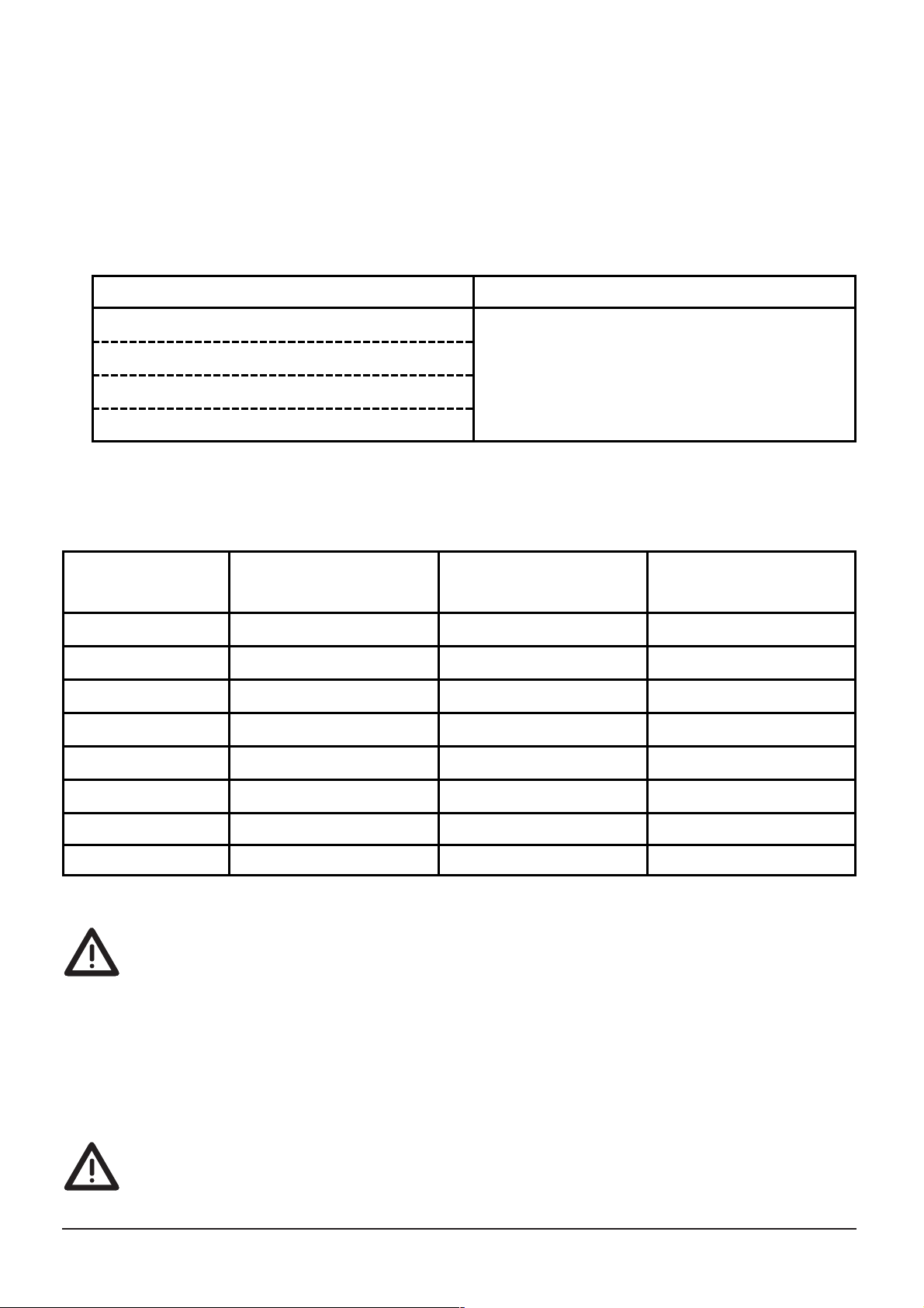
Eingestellte Parameter-Werte
Set parameter values
Valeurs de paramètre réglées
 Loading...