

Page 1
Operating instructions
Retro-reflective sensor
O7P2xx
UK
O7P200 / 01 11 / 2010
Page 2
1 Preliminary note
1.1 Symbols used
► Instruction
> Reaction, result
→ Cross-reference
Important note
Non-compliance can result in malfunctions or interference.
2 Functions and features
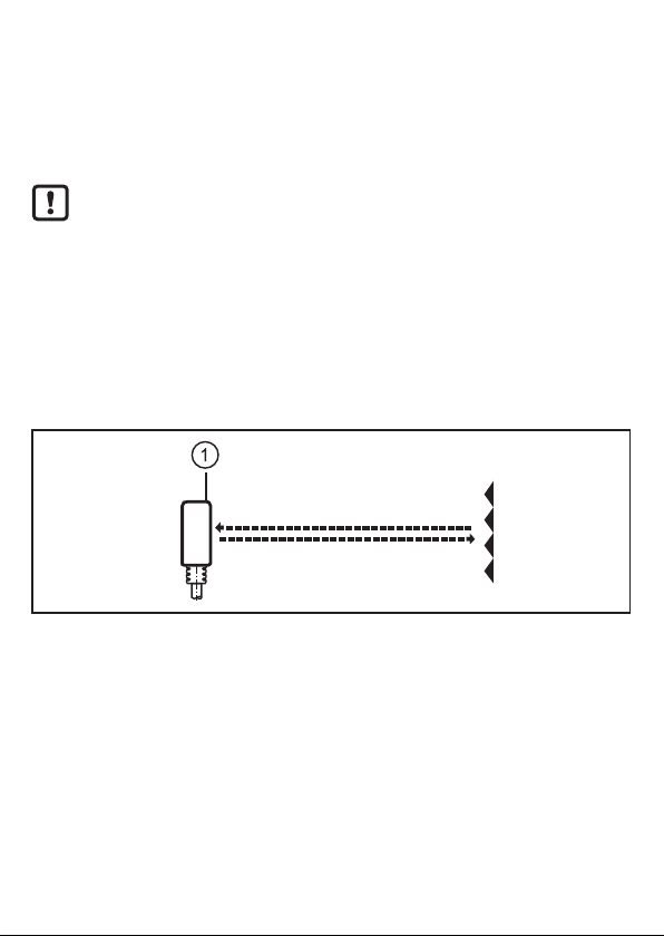
In conjunction with a prismatic reflector or reflective tape the retro-reflective sensor detects objects and materials without contact and indicates their presence by
a switching signal.
Range: → packaging or data sheet.
3 Installation
1: LED
► Fit the prismatic reflector or the reflective tape behind the object to be detected.
► Align the retro-reflective sensor to it and secure it to a bracket.
Maximum range only with accurate alignment.
2
Page 3
4 Electrical connection
The unit must be connected by a qualified electrician.
► The national and international regulations for the installation of electri-
cal equipment must be adhered to.
► Ensure voltage supply to EN 50178, SELV, PELV.
► Disconnect power.
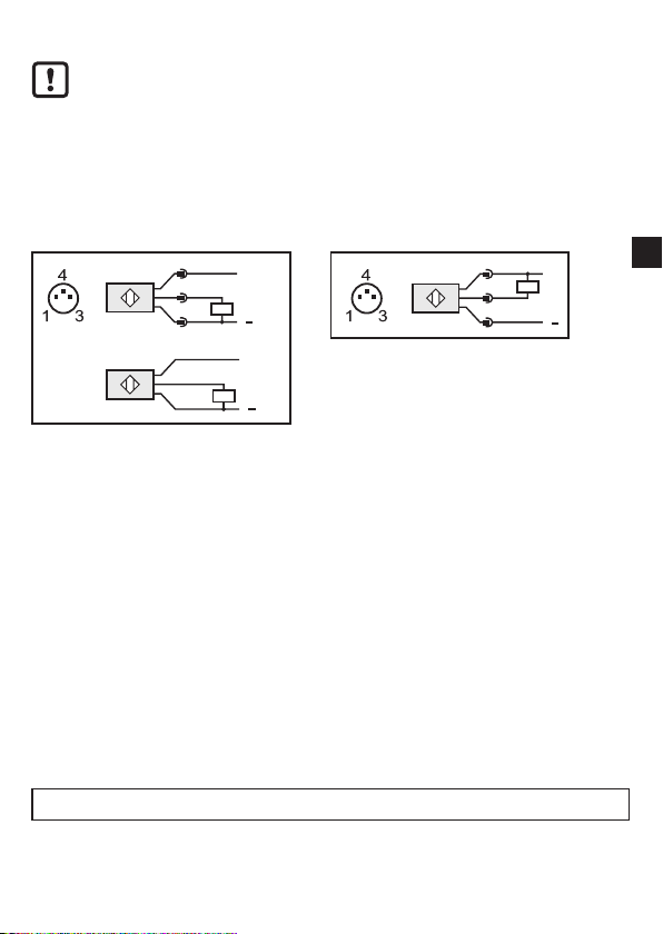
► Connect the unit as follows:
DC PNP DC NPN
Cable
BN
BK
BU
+
L
L
Core colours:
BN (brown), BU (blue), BK (black).
1
+
L
4
3
L
UK
5 Operation
► Check whether the unit operates correctly.
• Dark-on switching units (O7P-DPKG): The output is switched / the yellow LED
is lit when an object is detected.
• Light-on switching units (O7P-HPKG): The output is switched / the yellow LED
is lit when no object is detected.
6 Maintenance, repair and disposal
► Keep the front pane of the sensor free from soiling.
► For cleaning do not use any solvents or cleaning agents which could damage
the plastic material.
Technical data and further information at www.ifm.com
3
 Loading...