

IFM Electronic O6H7 Operating Instructions Manual

Operating instructions
Diffuse reflection sensor with
background suppression
O6H7xx
706457 / 00 11 / 2017
UK

2
Contents
1 Preliminary note ��������������������������������������������������������������������������������������������������� 3
1�1 Symbols used ������������������������������������������������������������������������������������������������3
2 Safety instructions �����������������������������������������������������������������������������������������������3
3 Functions and features ����������������������������������������������������������������������������������������3
4 Installation������������������������������������������������������������������������������������������������������������4
5 Operating and display elements ��������������������������������������������������������������������������5
5�1 Stability indication ������������������������������������������������������������������������������������������ 5
6 Electrical connection �������������������������������������������������������������������������������������������� 6
6�1 PNP ���������������������������������������������������������������������������������������������������������������6
6�2 NPN ���������������������������������������������������������������������������������������������������������������6
7 Settings ���������������������������������������������������������������������������������������������������������������� 7
7�1 Settings on the sensor ����������������������������������������������������������������������������������� 7
7�1�1 The sensor is to switch when the object is detected ����������������������������7
7�1�2 The sensor is not to switch when the object is detected ����������������������7
7�1�3 Set maximum range �����������������������������������������������������������������������������7
7�1�4 Programming unsuccessful ������������������������������������������������������������������8
7�1�5 Electronic lock ��������������������������������������������������������������������������������������8
7�2 Setting via IO-Link �����������������������������������������������������������������������������������������9
7�2�1 Adjustable parameters �������������������������������������������������������������������������� 9
7�2�2 Setting the range by means of background and object ���������������������� 11
7�2�3 Setting the range by means of background ���������������������������������������� 12
7�2�4 Setting the maximum range ����������������������������������������������������������������12
8 Operation ����������������������������������������������������������������������������������������������������������� 13
9 Maintenance, repair, disposal ���������������������������������������������������������������������������� 13
3
UK
1 Preliminary note
1.1 Symbols used
► Instruction
> Reaction, result
[…] Designation of pushbuttons, buttons or indications
→ Cross-reference
Information
Supplementary note�
Important note
Non-compliance can result in malfunctions or interference�
2 Safety instructions
According to the cULus approval
Caution - Use of controls or adjustments or procedures other than those
specified herein may result in hazardous radiation exposure�
Visible laser light; CLASS 1 LASER PRODUCT�
IEC 60825-1 : 2007 and IEC 60825-1 : 2014
Complies with 21 CFR 1040�10 except for deviations pursuant to Laser
Notice No� 50, dated June 2007�
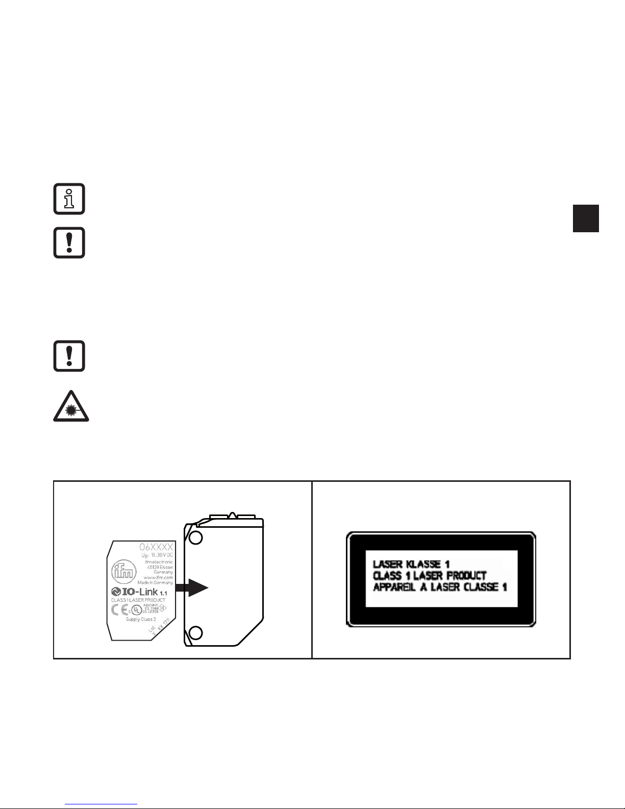
Position of the product label Additional label
3 Functions and features
The diffuse reflection sensor detects objects and materials without contact and
indicates their presence by a switching signal�

4
4 Installation
► Align the diffuse reflection sensor to the object to be detected (Fig� 1)�
> For exact alignment, use the accessories for fine adjustment�
► Secure it to a bracket�
Fig� 1
Fig� 2
Note
The objects to be detected are to
move transversely to the lens of the
sensor�
► In case of other directions of
movement it should be tested
before whether safe switching is
guaranteed�
Fig� 3
Shiny object
► In case of shiny object surfaces
and less shiny background surfaces the sensor should be mounted
at an angle of appox� 5 - 10°�
 Loading...