

IFM Electronic O3M150, O3M151, O3M161, O3M251, O3M160 Software Manual
...
Software Manual
ifm Vision Assistant
for mobile 2D/3D sensors
O3M150
O3M151
O3M160
O3M161
O3M250
O3M251
O3M260
O3M261
UK
706424 / 03 02/2018

ifm Vision Assistant O3M
Contents
1 Preliminary note ....................................................................6
1.1 Symbols used..................................................................6
1.2 Safety instructions ..............................................................6
1.3 Further documents ..............................................................6
2 System requirements ................................................................7
2.1 Software ......................................................................7
2.2 Hardware and accessories........................................................7
3 Installation.........................................................................8
3.1 Hardware .....................................................................8
3.2 Mounting accessories............................................................8
3.3 Software (ifm Vision Assistant).....................................................9
4 Start page........................................................................10
4.1 Find sensor...................................................................11
4.1.1 Direct search .............................................................11
4.1.2 Manual connection .........................................................13
4.2 Recent .....................................................................14
4.3 Replay .....................................................................15
4.4 Wiring .....................................................................17
4.5 Settings .....................................................................18
4.6 Close .....................................................................18
5 Structure of the user surface .........................................................19
5.1 Navigation bar ................................................................20
5.2 Status bar ....................................................................20
5.3 Main area ....................................................................20
6 Monitoring window .................................................................21
6.1 View Options .................................................................21
6.1.1 2D View .................................................................22
6.1.2 2D3D view ...............................................................26
6.1.3 3D view .................................................................29
6.1.4 Slider bar ................................................................35
6.2 Recording ....................................................................36
6.3 Service options................................................................38
7 Device setup......................................................................40
7.1 Device .....................................................................41
7.1.1 Name ...................................................................41
7.1.2 General settings wizard .....................................................41
7.1.3 Firmware update...........................................................50
7.1.4 Export settings ............................................................51
7.1.5 Import settings ............................................................51
7.1.6 Reboot the sensor .........................................................52
7.1.7 Online parameter setting ....................................................53
7.2 CAN settings..................................................................54
7.3 Ethernet .....................................................................55
8 Device Information .................................................................57
9 Calibration settings.................................................................58
9.1 What is calibration? ............................................................58
9.2 World coordinate system ........................................................60
9.3 Reference point of the device.....................................................60
9.4 Position of the device ...........................................................61
9.5 Reference point of the illumination unit .............................................63
9.6 Position of the illumination unit....................................................63
9.7 Mounting angle of the device .....................................................64
9.7.1 Normal mode .............................................................65
9.7.2 Expert mode..............................................................65
9.8 Automatic calibration ...........................................................66
9.8.1 Equipment failure causes....................................................69
2

ifm Vision Assistant O3M
10 Image settings ...................................................................70
10.1 Live image display ............................................................71
10.1.1 Pixel properties...........................................................72
10.2 Applying filters ...............................................................73
10.2.1 Example of area monitoring . . . . . . . . . . . . . . . . . . . . . . . . . . . . . . . . . . . . . . . . . . . . . . . . .73
10.3 Signal quality filter ............................................................73
10.4 Noise reduction filter...........................................................74
10.5 Detection of spray/fog/dust......................................................75
10.6 Soiling detection ..............................................................76
10.6.1 Setting the sensitivity ......................................................76
10.6.2 Removal of soiling ........................................................77
10.7 Frame rate ..................................................................77
10.8 Modulation frequency mode .....................................................78
10.8.1 Fixed modulation frequencies................................................78
10.8.2 Random modulation frequencies .............................................79
10.9 Intelligent data averaging .......................................................80
10.9.1 Operating principle ........................................................81
10.9.2 Example of a signal noise reduction...........................................81
10.9.3 Example for increasing the number of valid pixels................................82
10.10 Reflector threshold value ......................................................83
10.11 Measuring range.............................................................84
10.11.1 Exclusion area ..........................................................85
UK
11 2D overlay.......................................................................86
11.1 Overlay options...............................................................87
11.2 Pallet .....................................................................87
11.2.1 Add text.................................................................88
11.2.2 Adding a vector...........................................................89
11.2.3 Adding a graphic. .........................................................90
11.2.4 Live ticker ...............................................................91
11.3 Variant options of the OD firmware ................................................92
11.4 Variant options of the DI firmware.................................................93
11.4.1 Visualising 3D ROIs as a moving wall .........................................93
11.4.2 Visualisation of 3D ROIs as a projection on the floor ..............................98
11.4.3 Visualisation of 2D ROIs...................................................103
12 DI firmware - basic functions .......................................................107
12.1 ROI mode ..................................................................107
12.2 Global settings ..............................................................108
12.3 Several ROIs ...............................................................109
12.3.1 Min/max values and separation .............................................110
12.3.2 Result type . . . . . . . . . . . . . . . . . . . . . . . . . . . . . . . . . . . . . . . . . . . . . . . . . . . . . . . . . . . . . 111
12.3.3 Output value............................................................112
12.3.4 Reference value for min/max . . . . . . . . . . . . . . . . . . . . . . . . . . . . . . . . . . . . . . . . . . . . . . . 115
12.3.5 Existing ROIs ...........................................................117
12.3.6 Select group option.......................................................117
12.4 ROI groups .................................................................11 7
12.5 ROIs ....................................................................118
13 Firmware OD - object detection .....................................................119
13.1 Object recognition............................................................119
13.2 Collision avoidance...........................................................121
13.2.1 The "intelligent" collision avoidance mode .....................................122
13.2.2 Collision avoidance mode "Intelligent with side collision"..........................125
13.2.3 Collision avoidance mode "zone-based" ......................................126
14 Firmware LG - line guidance........................................................129
14.1 Max. angle to the driving direction ...............................................130
14.2 3D line structure .............................................................130
14.3 Automatic ground plane detection ...............................................131
14.4 Search area for line detection...................................................132
14.5 Additional crop edge settings ...................................................133
14.6 Filter on line output (low pass) ..................................................133
14.7 Steering computation .........................................................134
3

ifm Vision Assistant O3M
14.8 CAN data for vehicle movement.................................................134
15 Logic editor.....................................................................136
15.1 General creation rules ........................................................136
15.2 Place and connect modules ....................................................137
15.2.1 Generate example .......................................................138
15.2.2 Place new logic module in main area.........................................138
15.2.3 Delete a module .........................................................138
15.2.4 Set a module ...........................................................139
15.2.5 Connect modules . . . . . . . . . . . . . . . . . . . . . . . . . . . . . . . . . . . . . . . . . . . . . . . . . . . . . . . .141
15.2.6 Delete module connections ................................................141
15.3 Description of the "Input" modules ...............................................142
15.3.1 "Digital CAN input signals" module...........................................142
15.3.2 "Analogue CAN input signals" module ........................................142
15.3.3 Example for "Analogue CAN input signals" module..............................143
15.3.4 "Extrinsic calibration" module...............................................144
15.3.5 "Diagnostic" module ......................................................144
15.4 Description of the "Input" modules – Firmware DI ...................................146
15.4.1 "Basic function" module ...................................................146
15.4.2 "Input value of index" module...............................................147
15.4.3 Example for the "Input value of index" module..................................148
15.5 Description of the "Input" modules – Firmware OD ..................................149
15.5.1 "Object detection" module .................................................149
15.5.2 "Zone-based" module.....................................................151
15.5.3 "Time-based" module .....................................................151
15.5.4 "Input value of index" module...............................................152
15.6 Description of the "Input" modules – Firmware LG...................................154
15.6.1 "Line detection" module ...................................................154
15.6.2 "Input value of index" module...............................................155
15.7 Description of the "Memory function" modules......................................156
15.7.1 "Teach" module..........................................................157
15.7.2 Example for the "Teach" module ............................................157
15.7.3 "RAM write" module ......................................................159
15.7.4 "RAM read" module ......................................................159
15.7.5 Example: "Exponential smoothing filter" for "RAM write" / "RAM read" modules........160
15.7.6 Example "Event counter" for "RAM write" / "RAM read" modules ...................161
15.8 Description of the "Arithmetic" modules ...........................................162
15.8.1 Examples for processing input signals........................................164
15.9 Description of the "Digitalisation" modules.........................................167
15.10 Description of the "Logical functions" modules.....................................168
15.11 Description of the "Vector-specific functions" modules ...............................169
15.11.1 Example for the "Vector Min" module ........................................170
15.12 Description of the "Output" modules.............................................170
15.12.1 "Digital output" module...................................................170
15.12.2 Example for the "Digital output" module......................................171
15.12.3 "Analogue output" module ................................................172
15.12.4 Example for the "Analogue output" module ...................................173
15.13 Description of the switches "Enable CAN output" ..................................174
15.14 Description of the "Logic teach commands".......................................174
16 Annex .......................................................................175
16.1 Network settings.............................................................175
16.2 Text replacements and conditional codes..........................................178
16.2.1 Example . . . . . . . . . . . . . . . . . . . . . . . . . . . . . . . . . . . . . . . . . . . . . . . . . . . . . . . . . . . . . . .178
16.2.2 Hints for the usage .......................................................179
16.2.3 Text replacement - common codes for all variants ...............................179
16.2.4 Text replacement – DI specific codes .........................................180
16.2.5 Text replacement – OD specific codes ........................................181
16.3 Connect O3M to external devices ...............................................187
16.3.1 Ethernet (UDP) .........................................................187
16.3.2 CAN (J1939, CANOpen) ..................................................187
16.4 Glossary ...................................................................188
4

ifm Vision Assistant O3M
UK
Licences and trademarks
Microsoft
Corporation. Adobe® and Acrobat® are registered trademarks of Adobe Systems Inc.
All trademarks and company names used are subject to the copyright of the respective companies. This device contains (maybe modified)
open source software which is subject to special licensing terms. For copyright information and licensing terms please refer to: www.ifm.
com/int/GNU
For software subject to the GNU General Public License or the GNU Lesser General Public License the source code can be requested
against payment of the copying and shipping costs.
®
, Windows®, Windows Vista®, Windows 7®, Windows 8®, Windows 8.1® and Windows 10® are registered trademarks of Microsoft
5

ifm Vision Assistant O3M
1 Preliminary note
This document describes the following tasks with the 3D sensor of the O3M product family and the ifm
Vision Assistant software:
● Setting the parameters of the sensor (in the following referred to as "device")
● Setting up the applications using the ifm Vision Assistant
● Monitoring the applications with the ifm Vision Assistant
As soon as an application has been installed on the device, the device can be operated without the ifm
Vision Assistant.
1.1 Symbols used
► Instructions
> Reaction, result
[…] Designation of keys and buttons
"…" Name of display text
→ Cross-reference
Important note
Non-compliance may result in malfunction or interference.
Information
Supplementary note
1.2 Safety instructions
Please read the operating instructions prior to set-up of the device. Ensure that the device is suitable for
your application without any restrictions.
If the operating instructions or the technical data are not adhered to, personal injury and/or damage to
property can occur.
1.3 Further documents
Document
Operating instructions
Short instructions
The documents can be downloaded at:
www.ifm.com
6

ifm Vision Assistant O3M
2 System requirements
2.1 Software
The following software versions are required for operation:
● Operating system: Windows 7 (32/64 bits), Windows 8.1 (32/64 bits), Windows 10 (32/64 bits)
● Application software: ifm Vision Assistant 1.8.9.0
● Firmware DI: 4.21.x
● Firmware OD: 4.21.x
● Firmware LG: 4.21.x
UK
The required software can be found at
Other versions of the ifm Vision Assistant may contain changed or new functions which are not
described in this software manual.
www.ifm.com
.
2.2 Hardware and accessories
The following hardware is required for operation:
● Sensor of the O3M family
● PC with x86 or x64 type processor
● Screen: min. 1024 x 768 pixels, 32-bit colour depth
The following accessories are required for operation:
● Cable for network connection (Ethernet) for parameter setting, M12 connector/RJ45 connector, 4
poles, e.g. article no. E11898 (2 m), E12283 (5 m)
● Illumination unit
● Article no. O3M950 for O3M15x and O3M25x
● Article no. O3M960 for O3M16x and O3M26x
● MCI connection cable between sensor and illumination unit, article no. E3M121, E3M122 or E3M123
● Power supply cable for the illumination unit, article no. E3M131, E3M132 or E3M133
● Sensor cable for CAN bus and power supply, article no. E11596, E11597 or
EVC492 (EVC492 incl. terminating resistor)
● CAN USB interface "CANfox", article no. EC2112
● CANfox adapter cable, article no. EC2114
● Power supply 24 V, minimum 2.4 A, e.g. article no. DN4012
You will find further information about available accessories at
www.ifm.com
.
7
ifm Vision Assistant O3M
3 Installation
3.1 Hardware
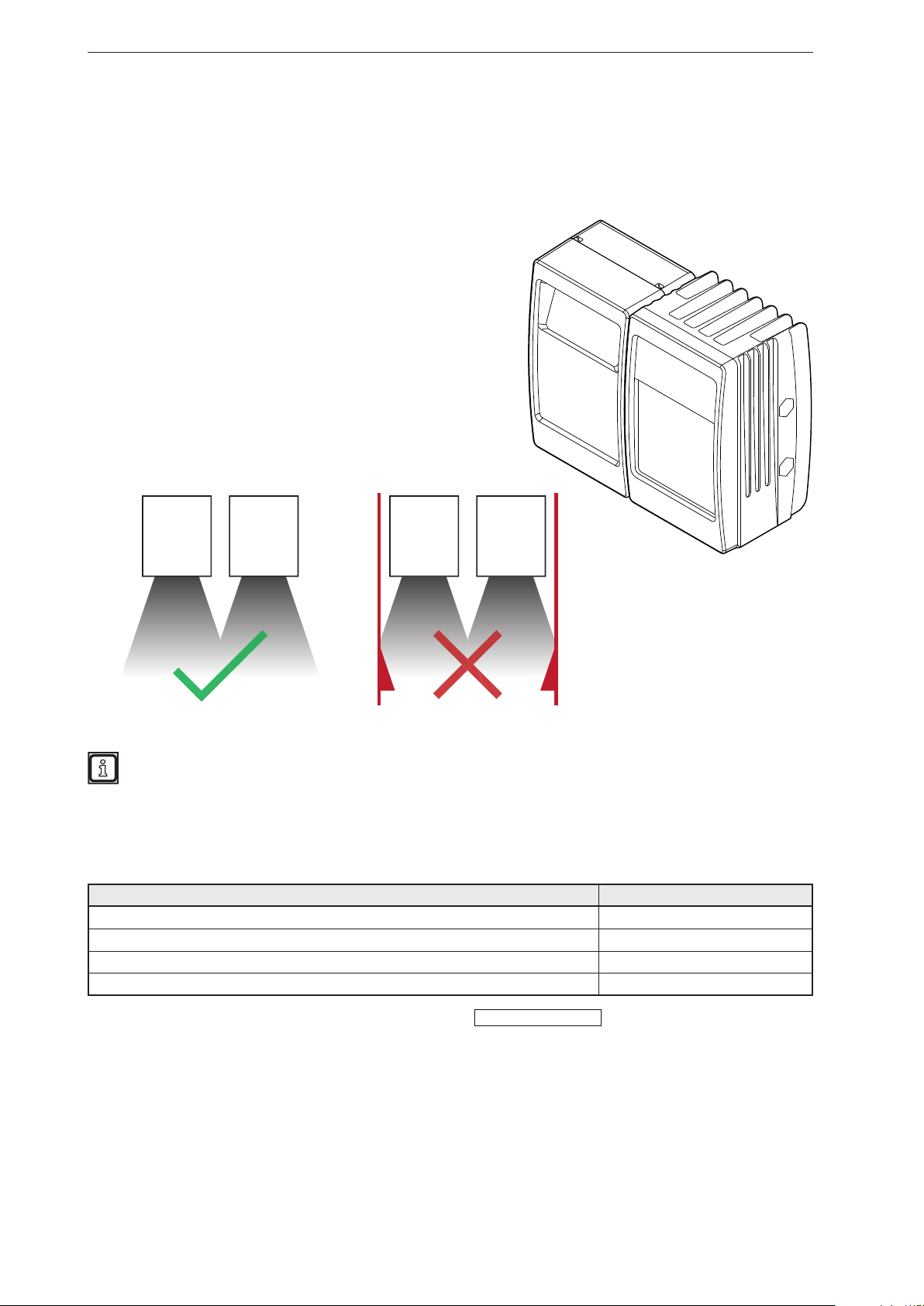
The mobile 3D sensor is operated as a system together with the illumination unit.
During installation note the following:
► Operate sensor and illumination unit in conjunction.
► Install sensor and illumination unit between 0 and 2.80 m
apart.
> Select the matching MCI connection cable depending on
the distance.
► Keep the area illuminated by the illumination unit free from
any obstructions in a close range (up to 50 cm)
(see figure below).
► Use cables with strain relief.
Sensor Illumination
unit
Sensor Illumination
unit
Further information about the electrical connection and the correct pin connection
→ Short instructions or operating instructions.
3.2 Mounting accessories
Depending on the intended mounting location and the type of installation, the following mounting
accessories are available:
Description Art. no.
Mounting set "U-tube" (u-shaped fixture with adjustment options for O3Mxxx housings) E3M100
Mounting set for rod mounting Ø 14 mm (clamp and bracket for O3Mxxx housings) E3M103
Rod, angled Ø 14 mm, length 130 mm, M12 E20939
Rod, angled Ø 14 mm, length 200 mm, M12 E20941
You can find more information about the accessories at:
8
www.ifm.com
ifm Vision Assistant O3M
3.3 Software (ifm Vision Assistant)
► Insert the data carrier with the ifm Vision Assistant software.
Alternative: Download ifm Vision Assistant software from the ifm website:
www.ifm.com → Service → Download
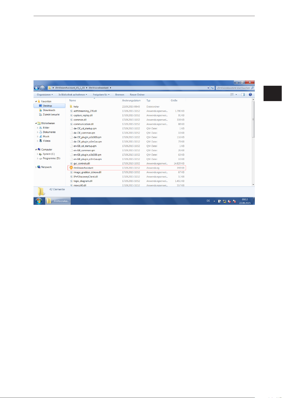
► Copy the Zip file "ifmVisionAssistant" into an appropriate directory on the PC and unzip.
► Start the "ifmVisionAssistant" application file.
UK
> The start page of the ifm Vision Assistant opens.
► If the start page does not appear after 5–10 seconds, please check if the software requirements are
complied with and if all files are properly unzipped.
9
ifm Vision Assistant O3M
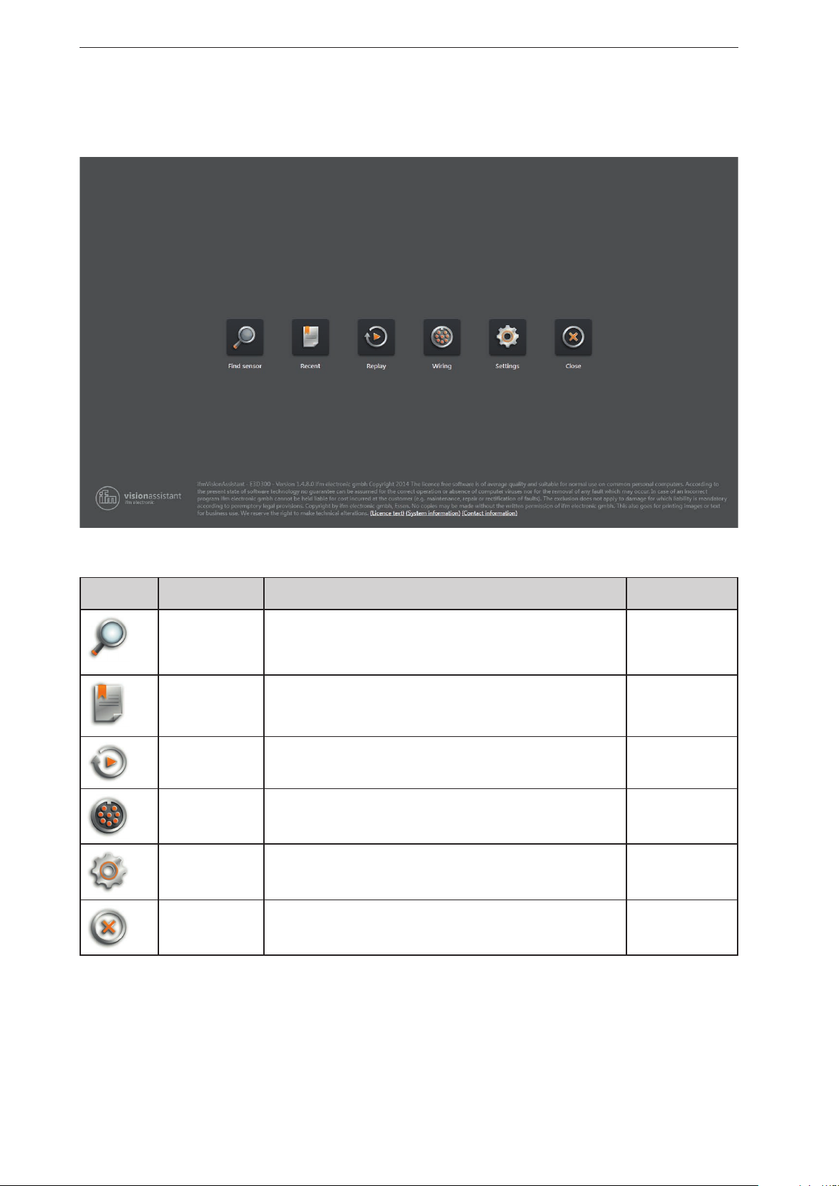
4 Start page
On the start page, the basic functions of the ifm Vision Assistant can be selected.
Basic functions of the start page:
Symbol name Function The device must
Find sensor Connection with the new added device.
Searches for connected devices and displays a selection list of the
devices found (→ „4.1 Find sensor“).
Recent Connection with the device that has connected itself successfully once
before.
Opens a selection list of the devices which have been connected
before (→ „4.2 Recent“).
Replay Plays recorded sequences (→ „4.3 Replay“). no
Wiring Display of the wiring of the voltage supply.
The display is used to simplify the connection during set-up
(→ „4.4 Wiring“).
Settings Language and image mode setting of the user interface
(→ „4.5 Settings“).
Close Quits the ifm Vision assistant. no
be connected
yes
yes
no
no
10
ifm Vision Assistant O3M
4.1 Find sensor
With this function, it is possible to search for the connected devices or to establish a manual connection
with a connected device.
► Ensure that the device and the PC are ready for operation and that there is a CAN bus and Ethernet
connection.
> If the device is neither connected via CAN bus nor via Ethernet, only a restricted 3D visualisation is
possible and the connection is not automatically established.
> If the device is connected via Ethernet and not via CAN bus, no parameters can be written to the
device. Only monitoring is possible.
If possible, always connect the device both via CAN bus and Ethernet. Otherwise, functionality
is restricted. This documentation assumes that the device is connected via both CAN bus and
Ethernet.
The following ports must be open (if necessary, adjust the settings of the firewall):
● UDP: 42000
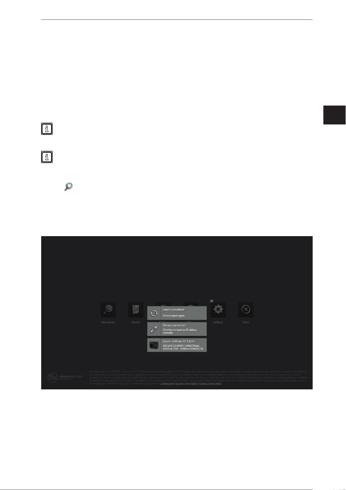
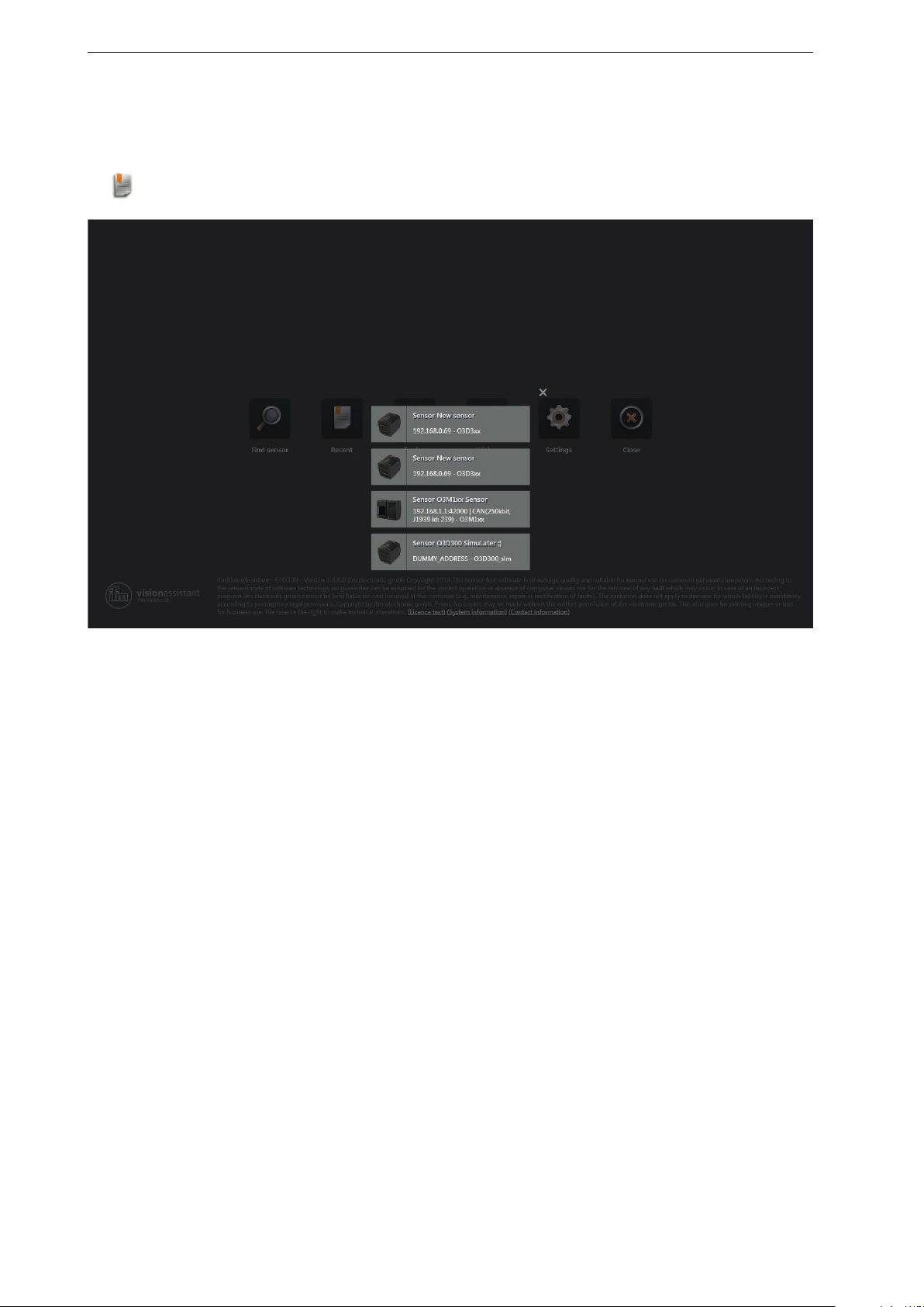
4.1.1 Direct search
UK
► Click .
> The ifm Vision Assistant searches for connected devices via the Ethernet connection.
> All devices found are shown in a list for selection. If there is a CAN bus connection, the CAN settings
are shown additionally.
► Click on the button of the found device in order to establish connection.
► If the ifm Vision Assistant does not find a device automatically:
● Check if the device is correctly connected and ready for operation and click on [Search completed]
to start a new search.
● Connect the device directly with the PC without any additional network devices in the connection
(e.g. router).
● Click on [Manual connection] and enter the connection settings manually
(→ „4.1.2 Manual connection“).
11

ifm Vision Assistant O3M
Buttons and notifications after the direct search:
Button and notification Description
Starts a new search.
Makes it possible to enter the IP address manually (→ „4.1.2 Manual connection“).
Shows connection settings of the CAN bus such as IP address, name of the device and
the firmware version.
Connects the device and continues according to the application data.
12
ifm Vision Assistant O3M
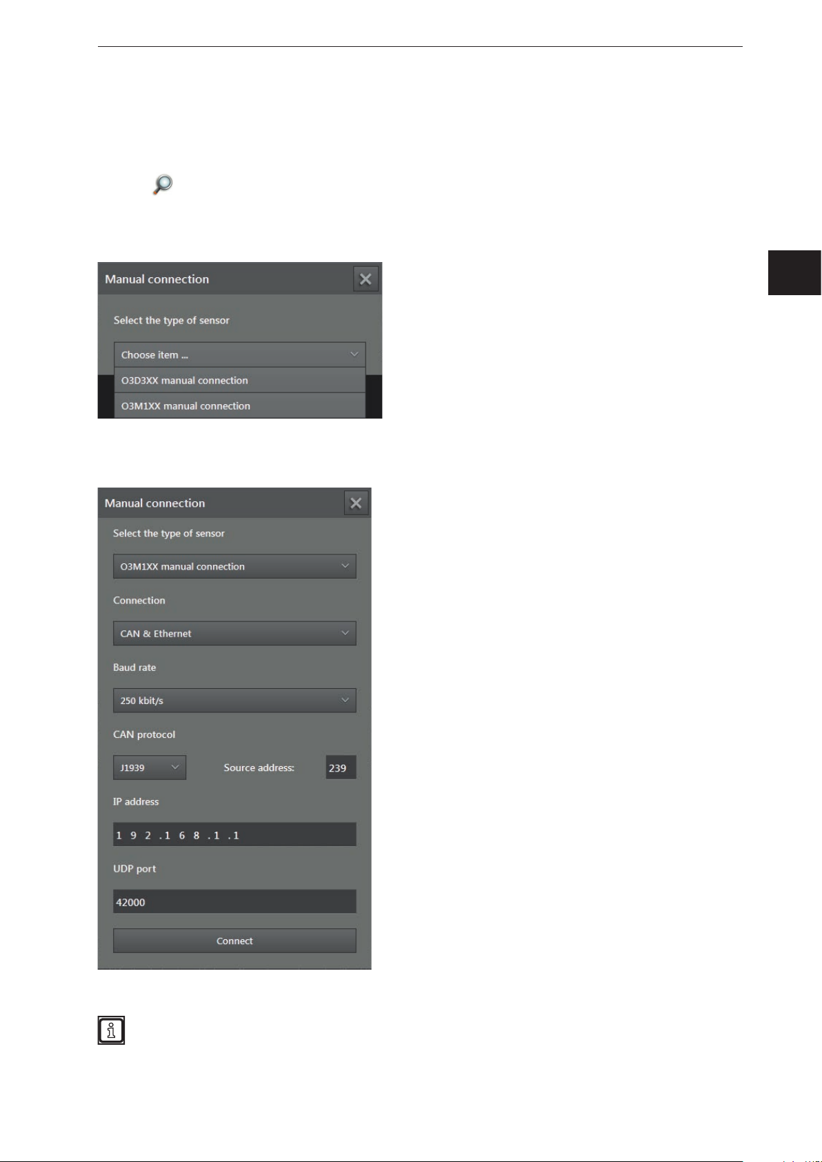
4.1.2 Manual connection
If the ifm Vision Assistant was not able to establish an automatic connection with the device, the
connection settings can be entered manually via the button [Manual connection].
► Click
► Click on [Manual connection].
> The "Manual connection" window is displayed:
► Select "O3M manual connection".
► Enter the IP address of the device (standard: 192.168.0.69).
.
UK
► Click on [Connect].
The IP addresses of device and PC with ifm Vision Assistant must be in the same subnet.
13
ifm Vision Assistant O3M
4.2 Recent
This function opens a selection list of the devices that have already been connected.
Click .
►
► Ensure that the corresponding device is connected with the PC via Ethernet or available in the
network.
► Click on the device in the selection list.
> The ifm Vision Assistant establishes a connection with the device.
14
ifm Vision Assistant O3M
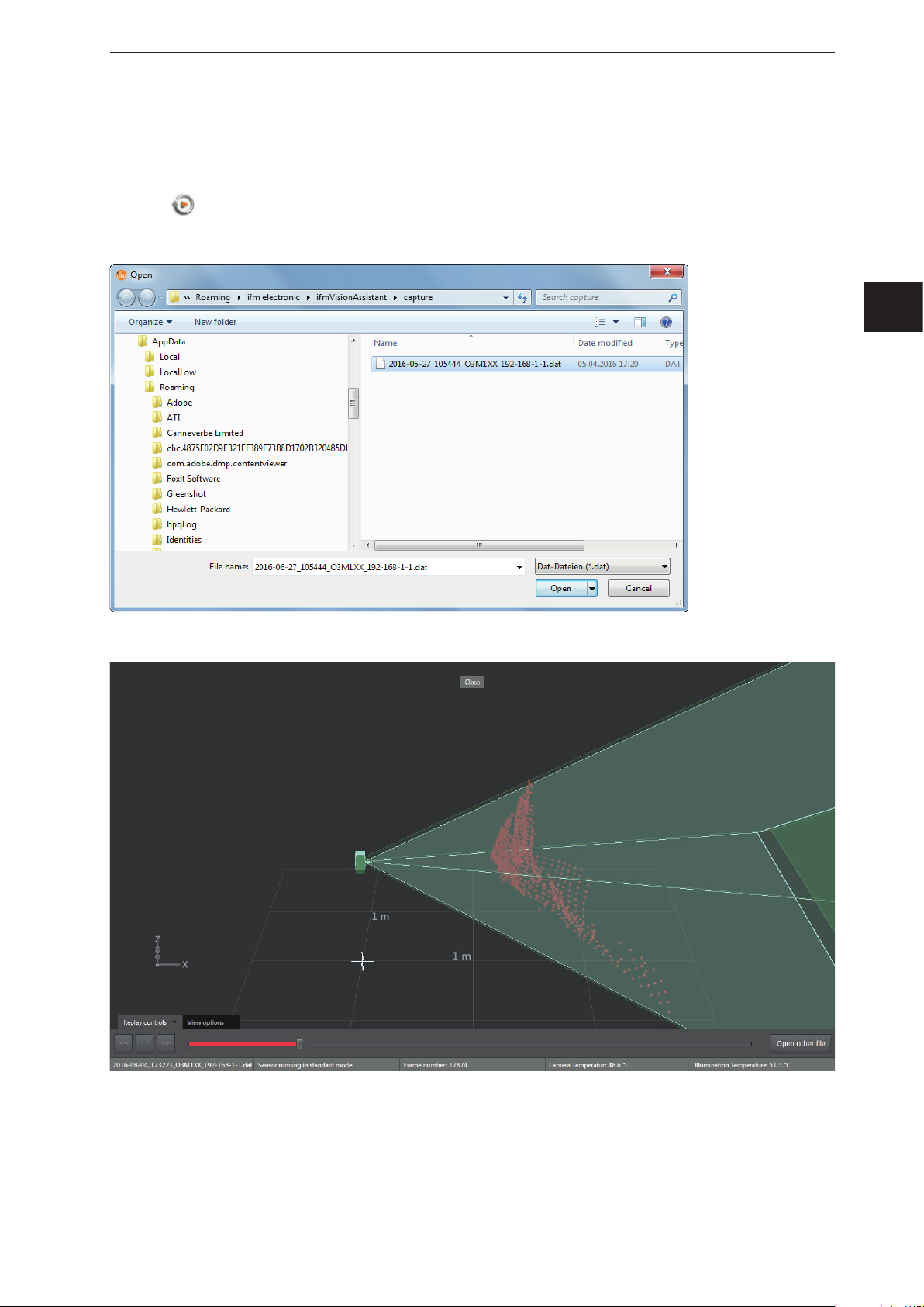
4.3 Replay
With this function, data that has been recorded can be viewed (→ „6 Monitoring window“). No connection
to a device is needed.
► Click
► Select the required file (*.dat) and click on [Open].
> The playback screen appears.
.
UK
15

ifm Vision Assistant O3M
Options on the playback screen:
Tab Option / button Description
Replay
controls
View options – → „6.1 View Options“
–
pause
Down
Up
Start
Progress bar Indicates the current position in the recording.
Stops playback.
Stops playback and shows the previous picture.
Stops playback and shows the next picture.
Continues playback.
By clicking on a position in the progress bar, playback continues at the
corresponding image.
Opens a window in which a file can be selected.
Closes the playback screen and opens the start screen.
► Click on [Close] to return to the start screen.
16
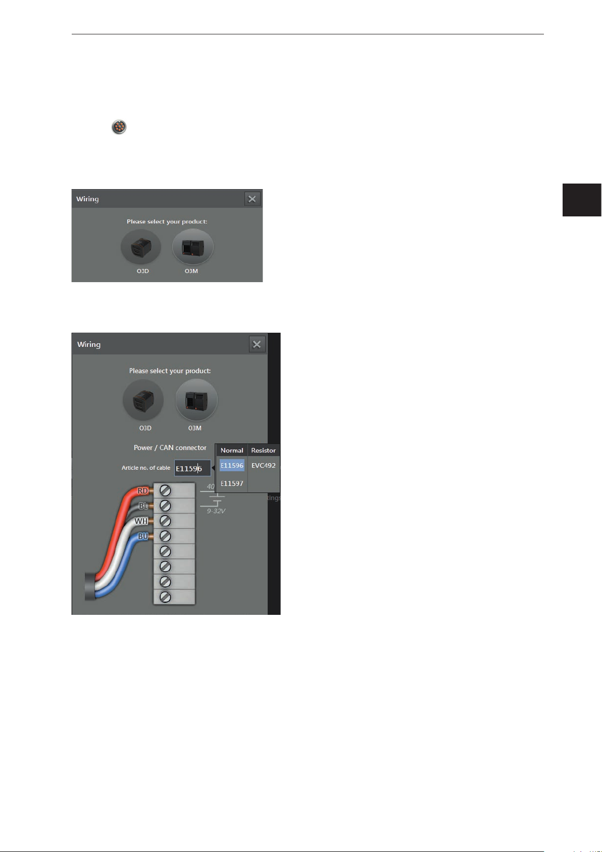
4.4 Wiring
This function allows correct wiring of the voltage supply of the 5-pole connector.
ifm Vision Assistant O3M
► Click
► Selected article [O3M].
> Only necessary if a new device has been selected.
► Click on the selection field [Article number] and select a connection cable from the selection list.
> For the selected cable, the wiring of the voltage supply and the CAN bus is shown.
.
UK
17

ifm Vision Assistant O3M
4.5 Settings
You can use this function to change the language and to switch between full screen and window view.
► Click
.
> The "Settings" window is displayed.
Options in the settings window:
Field Option Description
Language English Selection of the available language.
German
etc.
Full screen
on
"English" is set by default.
Switches between full screen (on) and window view (off).
Full screen is set by default.
off
With the F11 key, you can switch between full screen and window view at any time.
4.6 Close
► Click on to quit the ifm Vision Assistant.
18
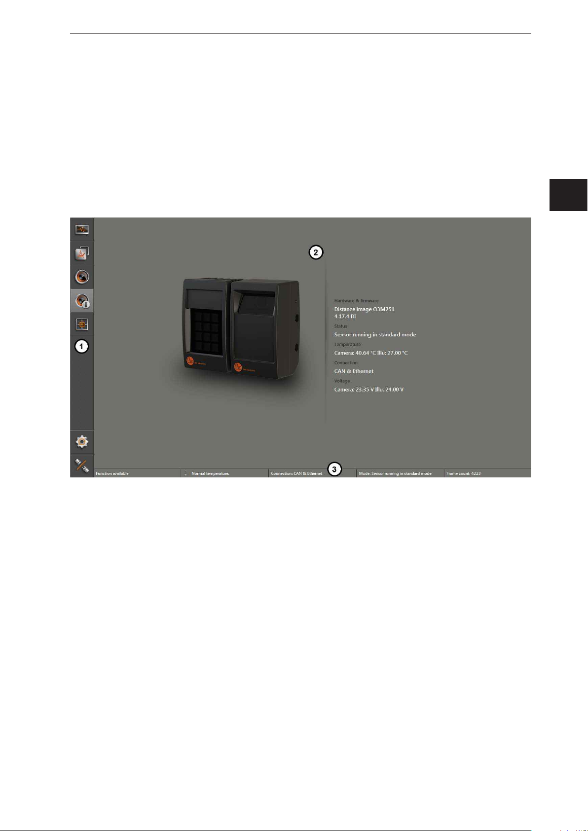
5 Structure of the user surface
The screen of the ifm Vision Assistant has the following areas:
1. navigation bar:
In the navigation bar on the left, the required option can be selected
(→ „5.1 Navigation bar“).
2. main area:
The main area shows the selected option or application.
3. Status bar:
The status bar at the bottom of the screen shows the status information of the device.
ifm Vision Assistant O3M
UK
1: Navigation bar
2: Main area
3: Status bar
19
ifm Vision Assistant O3M
5.1 Navigation bar
The navigation bar on the left features the following options:
Button Name Description
Monitor
Applications
Device setup
Device information
Calibration Settings
Settings Opens the "Settings" window (→ „4.5 Settings“).
Disconnect
Opens a 2D or 3D view and shows the current device data
(→ „6 Monitoring window“).
Opens an overview of the applications (→ „11 2D overlay“).
Managing and adjusting the applications.
Opens the device setup (→ „11 2D overlay“).
For device settings that are independent of the applications.
Shows basic information (e.g. hardware firmware, device status) (→ „8 Device
Information“).
In the calibration settings, the device is calibrated for the intended application
(→ „9 Calibration settings“).
Disconnects the ifm Vision Assistant from the device.
The ifm Vision Assistant returns to the start screen.
5.2 Status bar
The status bar at the bottom of the screen gives the following information:
● Availability status
● Temperature information of the device, e.g. "Temperature normal"
● Connection type of the device, e.g. CAN and Ethernet
● Error mode of the device, e.g. xyz
● Frame count shows the number of frames
The availability status gives information about:
● Usability of the data
● Recognition of soiling (sensor disk dirty or frosted)
● Recognition of spray (can be activated in the programming mode)
5.3 Main area
While the device is operated, the main area shows the monitoring window
(→ „6 Monitoring window“).
When the device is being set up, the main area shows the corresponding screen pages.
20
ifm Vision Assistant O3M
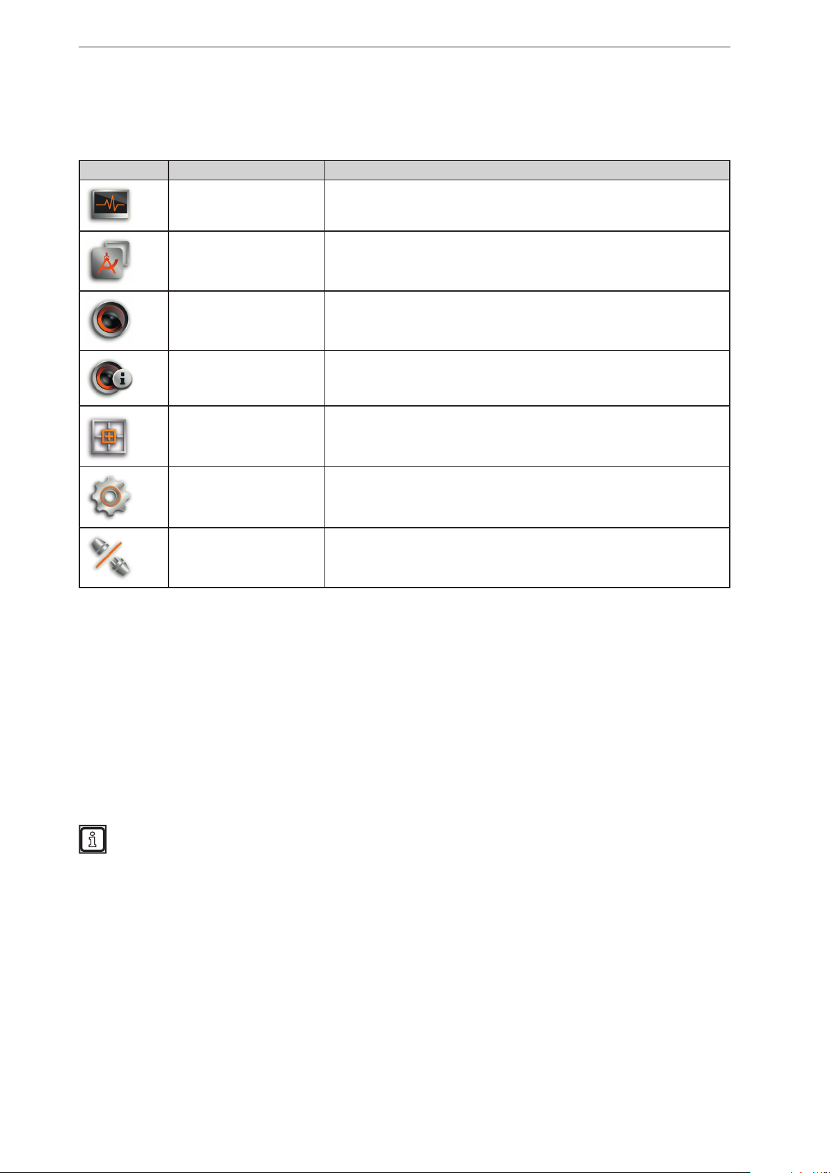
6 Monit oring window
The monitoring window is activated via the [Monitor] button. The unit is in the operating mode. In the
monitoring window, the running application can be monitored but neither interrupted nor changed.
Additionally, system and error information is indicated.
► Click
.
UK
Under the live image of the device, you see the following tabs:
● [View options] (→ „6.1 View Options“)
● [Record options] (→ „6.2 Recording“)
● [Service options] (→ „6.3 Service options“)
6.1 View Options
► Select options:
Button Name Description
2D view Shows the device data as a 2D visualisation (→ „6.1.1 2D View“).
2D3D view Shows the device data as 2D/3D visualisation (→ „6.1.2 2D3D view“).
3D view Shows the device data as a 3D visualisation (→ „6.1.3 3D view“).
The figures in the following chapters are examples. Depending on the objects and the individual
settings, the representation may differ significantly.
21

ifm Vision Assistant O3M
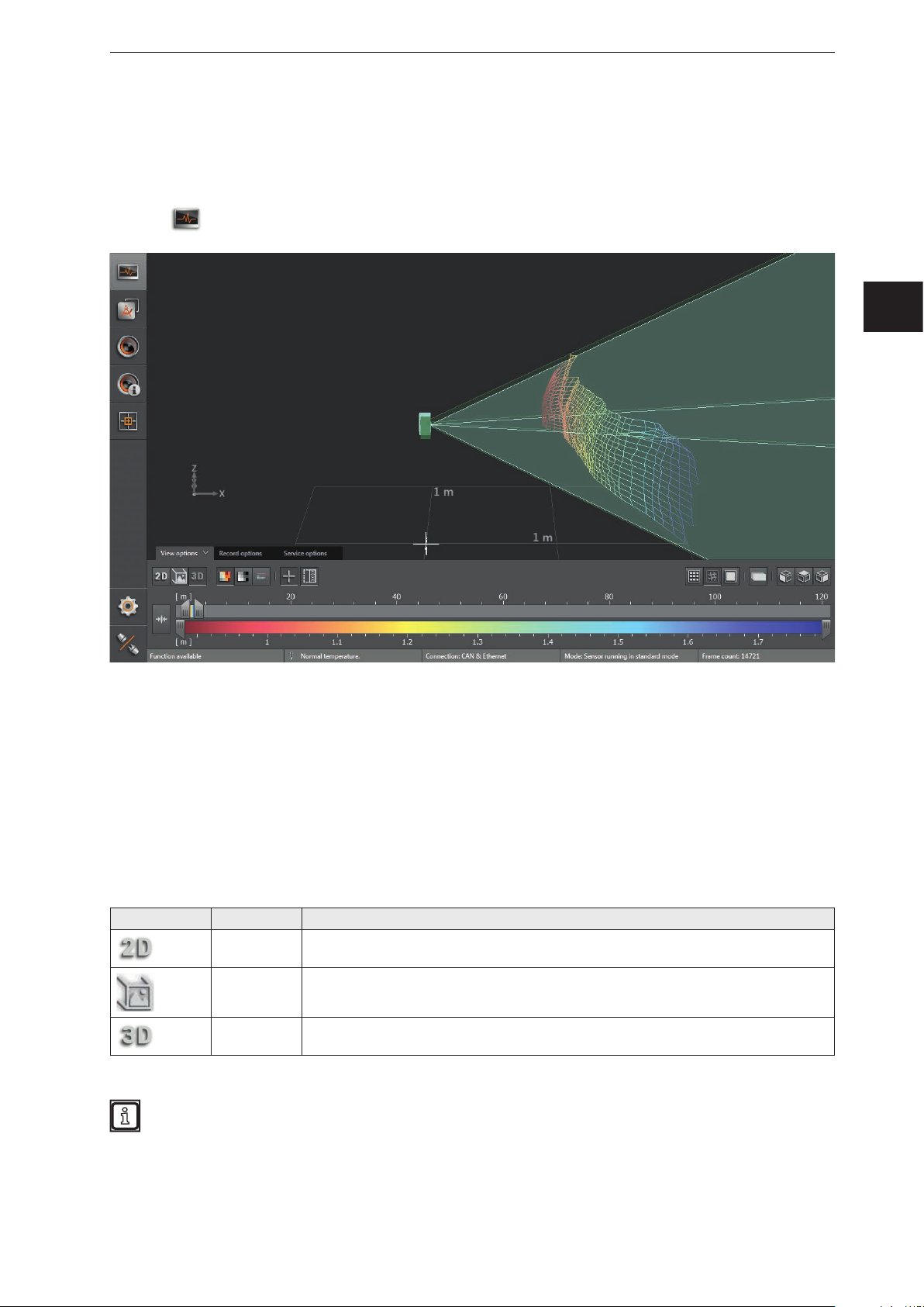
6.1.1 2D View
► Click to show the 2D view.
► Adjust the 2D view.
The following settings are available in the tab "View options":
Button Name Description
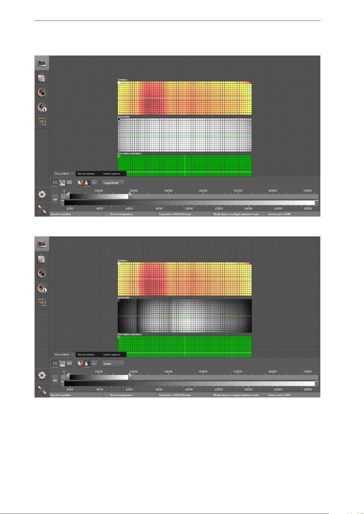
Distance image Visualises the pixels in the 2D view in relation to the distance values.
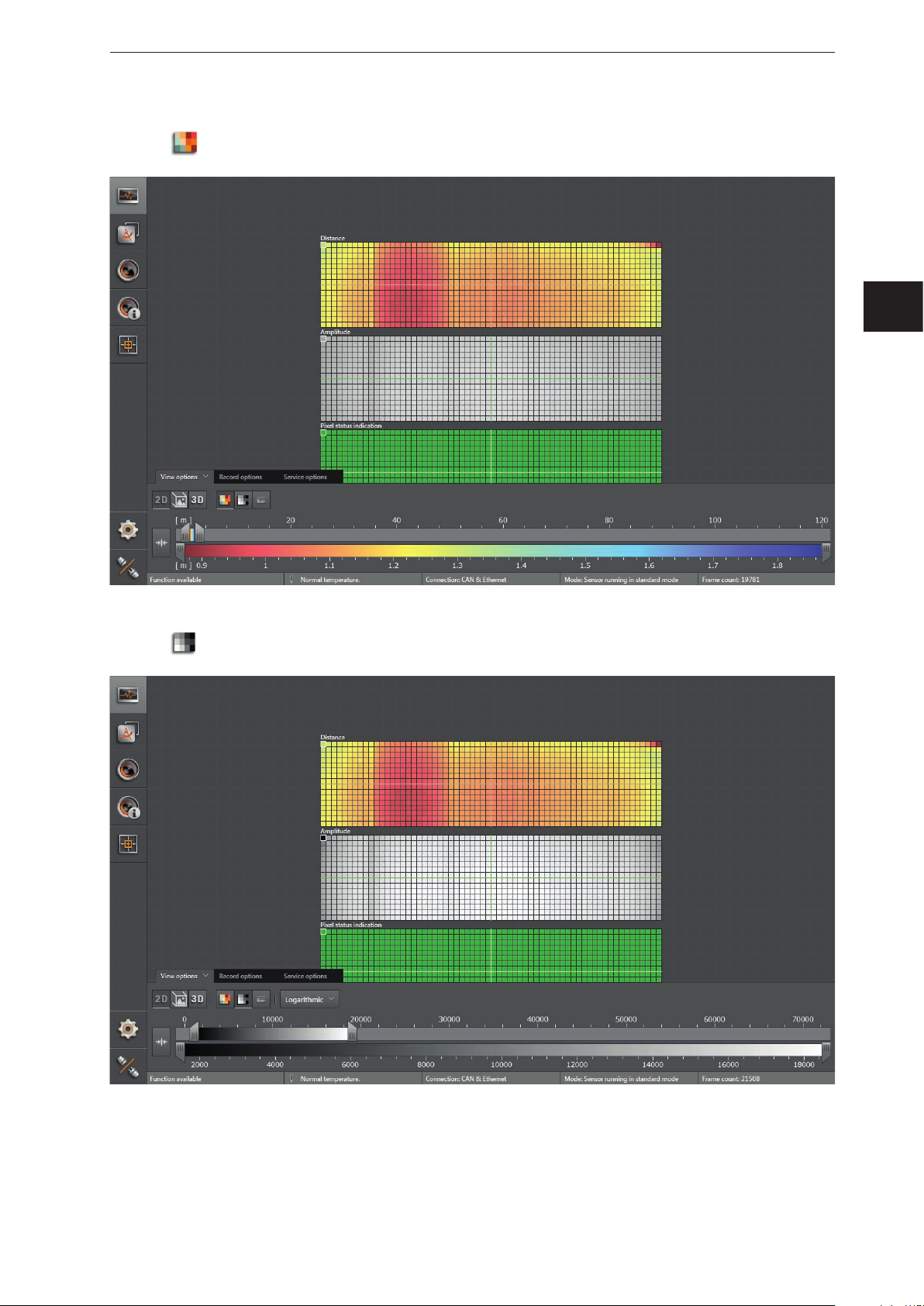
Amplitude image
Logarithmic
Linear
Rescaling
Visualises the pixels in the 2D view in relation to the amplitude values in levels of grey
(brightness).
Visualises the amplitude values of the 2D view in logarithmic levels of grey (only
available for the amplitude image).
Visualises the amplitude values of the 2D view in linear levels of grey (only available for
the amplitude image).
The "linear" view is particularly helpful when setting up the image.
Sets the colour range automatically to an adequate area. The settings of the slider bars
are dismissed.
The display settings (e.g. [Logarithmic] or [Linear]) only change the calculation and type of
visualisation. The application itself is not affected by it.
22
Distance image
ifm Vision Assistant O3M
► Click
to display the distance image.
UK
Amplitude image
► Click
to display the amplitude image.
► Select the required view via [Logarithmic] or [Linear].
23
ifm Vision Assistant O3M
Logarithmic view:
Linear view:
24
ifm Vision Assistant O3M
Pixel properties
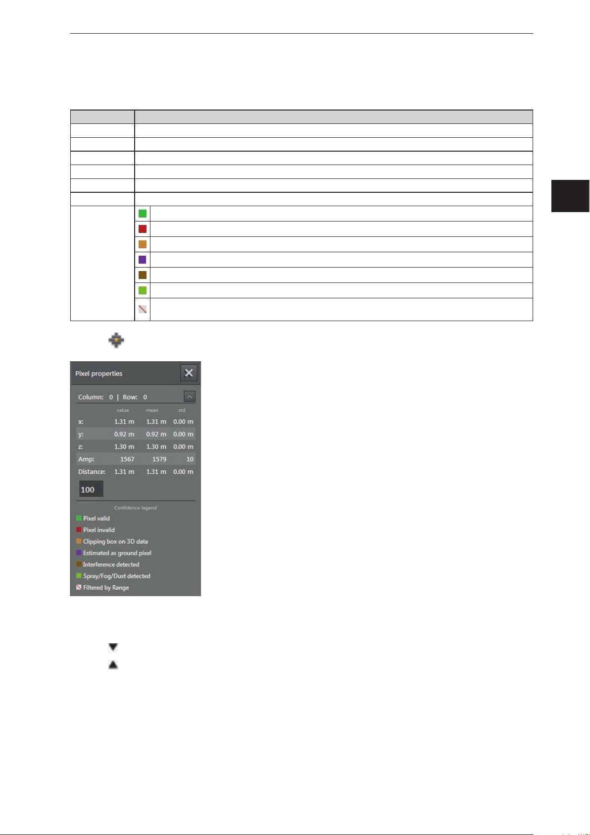
Via this function, the following information about the selected pixel can be displayed:
Field Description
Column | Row Indicates the number of columns and rows of a pixel
x x coordinate of the pixel: current measured value and deviation (related to the world coordinate system)
y y coordinate of the pixel: current measured value and deviation (related to the world coordinate system)
z z coordinate of the pixel: current measured value and deviation (related to the world coordinate system)
Amplitude Amplitude of the pixel
Distance Distance of the pixel to the device
Valid pixel
Invalid pixel (signal too strong or too weak)
Spatially filtered 3D data (→ „10.11 Measuring range“)
Colour legend
Estimated as ground
Pixel detected as disturbed (interference can be produced by neighbouring O3Ms)
Spray / fog / dust detected
Filtered according to distance (if the pixel is outside the set distance, the ifm Vision Assistant is marked as
invalid. )
UK
► Click to open the "pixel properties" window.
► Click on the pixel in the 2D view.
> Position, amplitude and distance of the pixel are indicated in metres.
► Click
► Click
to open extended information.
to close extended information.
25
ifm Vision Assistant O3M
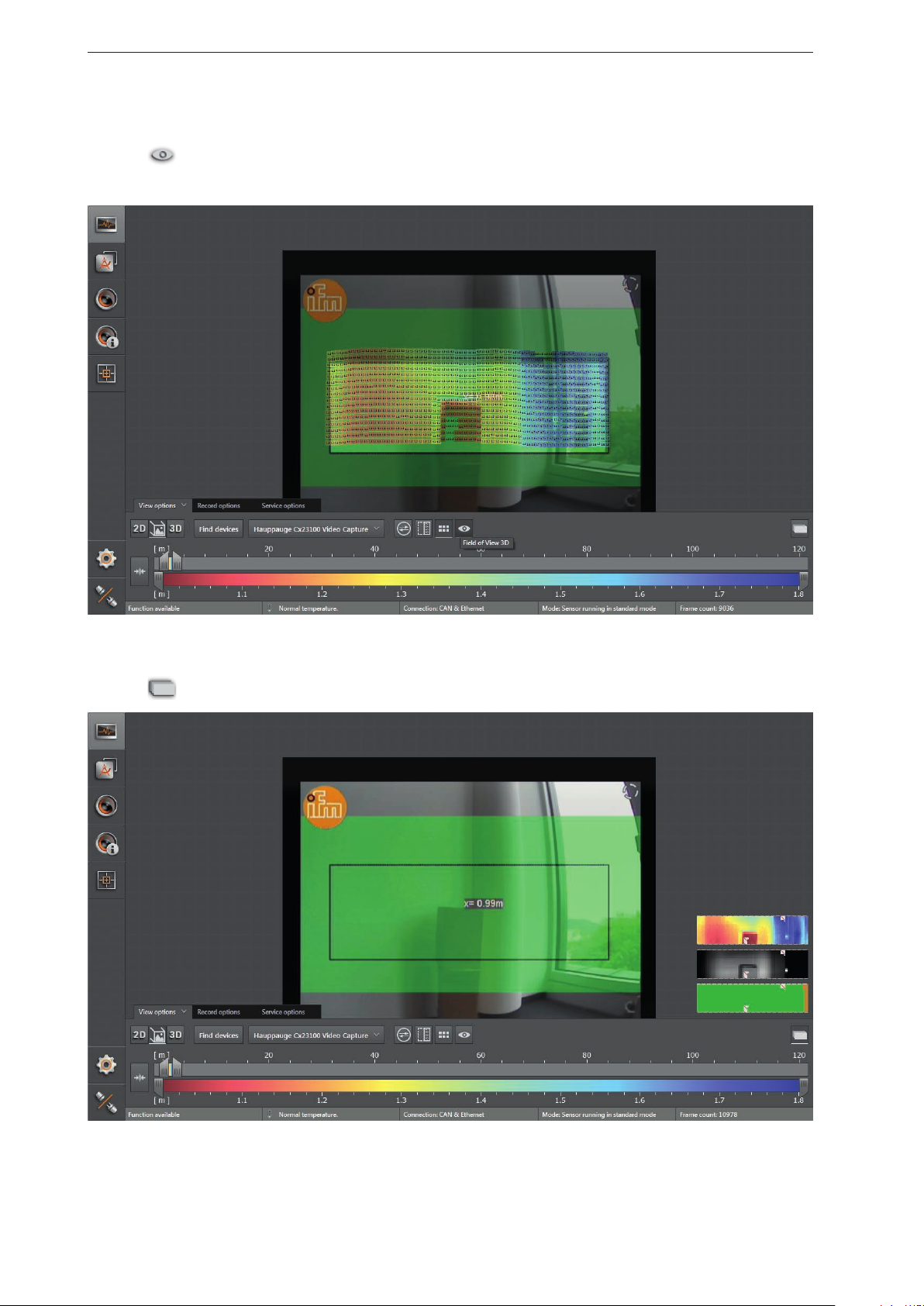
6.1.2 2D3D view
The 2D3D view is only possible with the O3M2xx devices.
► Click
to show the 2D3D view.
► Adjust the 2D3D view.
The following settings are available in the tab "View options":
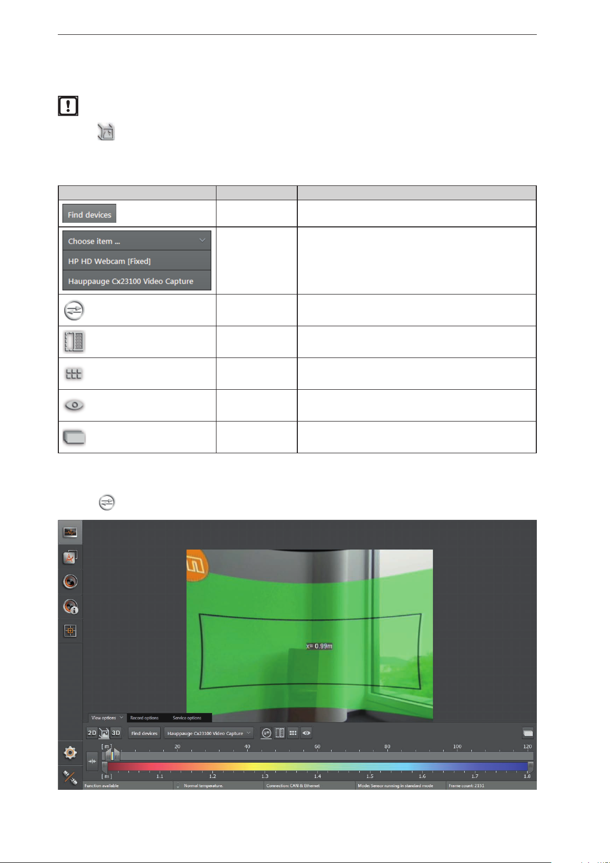
Button Name Description
Search for video
converter
Select video
converter
2D rectification Eliminates geometric distortions in the image data.
Spatially filtered 3D
data
Pixel Shows the distance values per pixel.
Visible 3D range Highlights the visible 3D range.
Searches for connected compatible video converters.
Connects a compatible video converter.
Shows the spatially filtered 3D data.
2D rectification
► Click
to activate the 2D rectification.
2D preview Shows the 2D data as an overlay within the 2D3D view.
26
Spatially filtered 3D data
ifm Vision Assistant O3M
► Click
> Which 3D data is to be spatially filtered can be configured in chap. „10.11 Measuring range“.
to activate the spatially filtered 3D data.
UK
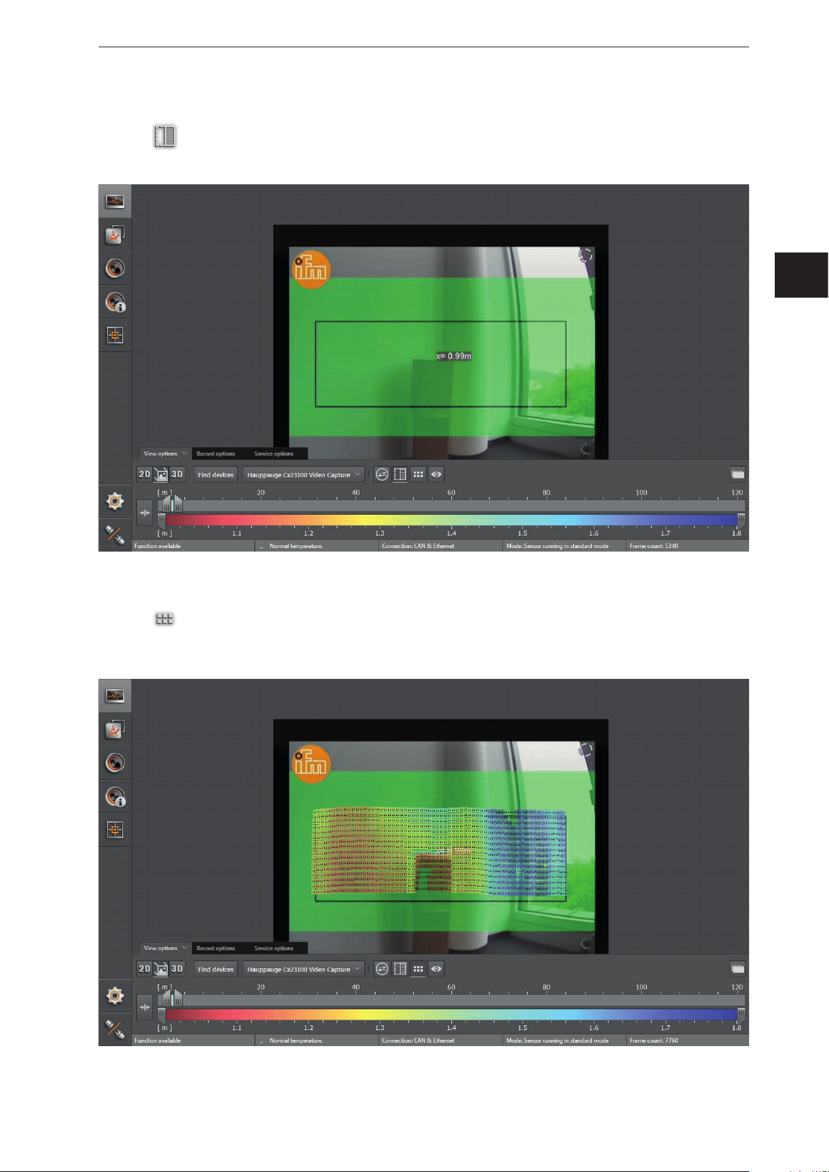
Pixel
► Click
> Each pixel contains the distance as a numeric value. The colour shade depends on the measured
distance of the pixel and the setting of the colour scale (→ „6.1.4 Slider bar“).
to display the distance values per pixel.
27
ifm Vision Assistant O3M
Visible 3D range
► Click
> The area outside the visible 3D range is visualised in a darker shade.
to activate the visible 3D range.
2D preview
► Click
to show the 2D data as an overlay within the 2D3D view.
28
ifm Vision Assistant O3M
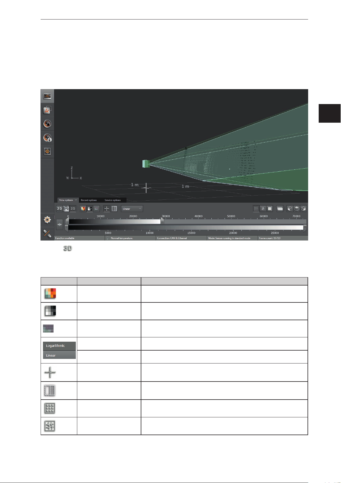
6.1.3 3D view
The 3D view is a visualisation of the 3D views of the device and the illumination unit. The individual vision
cones of the 3D views have different colours:
● Device: green
● Illumination unit: light green
UK
► Click to show the 3D view.
► Adjust the 3D view.
The following settings are available in the tab "View options":
Button Name Description
Distance image Visualises the pixels in the 3D view in relation to the distance values.
Amplitude image
Confidence
Logarithmic
Linear
Origin Shows and hides the origin of the coordinate system in the 3D view.
Spatially filtered 3D data Shows the spatially filtered 3D data.
Dots Shows the data as a pixel cloud.
Visualises the pixels in the 3D view in relation to the amplitude values in levels
of grey (brightness).
Shows the pixels of the 3D view with the corresponding status from the colour
legend (→ Pixel properties, previous page).
Visualises the amplitude values of the 3D view in logarithmic levels of grey (only
available for the amplitude image).
Visualises the amplitude values of the 3D view in linear levels of grey (only
available for the amplitude image).
Grid Shows the data as a grid.
29
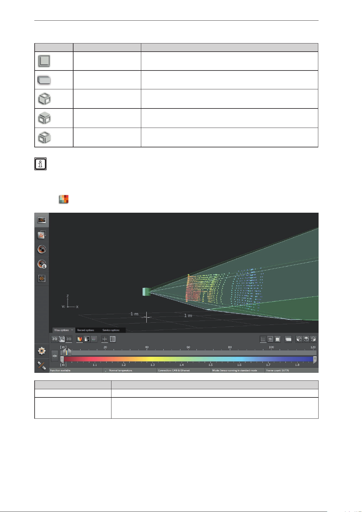
ifm Vision Assistant O3M
Button Name Description
Surface model Shows the ascending slopes as colour gradients.
2D preview Shows the 2D data as an overlay within the 3D view.
Default view 1 Turns the 3D view to the xy level.
Default view 2 Turns the 3D view to the xz level.
Default view 3 Turns the 3D level to the yz level.
The settings of the view (e.g. [Logarithmic] or [Linear]) only change the calculation and type of
visualisation. The application itself is not affected by it.
Distance image
► Click
to display the distance image.
Visualisation in the 3D image Description
Pixel position Space coordinate of the point (x, y, z coordinates).
Distance (x-coordinate).
Pixel colour
The colour shade depends on the measured distance of the point and the setting of the colour
scale (→ „6.1.4 Slider bar“).
30
 Loading...