

Page 1

Software Manual
ifm Vision Assistant
for mobile 2D/3D sensors
O3M150
O3M151
O3M160
O3M161
O3M250
O3M251
O3M260
O3M261
UK
706424 / 03 02/2018
Page 2

ifm Vision Assistant O3M
Contents
1 Preliminary note ....................................................................6
1.1 Symbols used..................................................................6
1.2 Safety instructions ..............................................................6
1.3 Further documents ..............................................................6
2 System requirements ................................................................7
2.1 Software ......................................................................7
2.2 Hardware and accessories........................................................7
3 Installation.........................................................................8
3.1 Hardware .....................................................................8
3.2 Mounting accessories............................................................8
3.3 Software (ifm Vision Assistant).....................................................9
4 Start page........................................................................10
4.1 Find sensor...................................................................11
4.1.1 Direct search .............................................................11
4.1.2 Manual connection .........................................................13
4.2 Recent .....................................................................14
4.3 Replay .....................................................................15
4.4 Wiring .....................................................................17
4.5 Settings .....................................................................18
4.6 Close .....................................................................18
5 Structure of the user surface .........................................................19
5.1 Navigation bar ................................................................20
5.2 Status bar ....................................................................20
5.3 Main area ....................................................................20
6 Monitoring window .................................................................21
6.1 View Options .................................................................21
6.1.1 2D View .................................................................22
6.1.2 2D3D view ...............................................................26
6.1.3 3D view .................................................................29
6.1.4 Slider bar ................................................................35
6.2 Recording ....................................................................36
6.3 Service options................................................................38
7 Device setup......................................................................40
7.1 Device .....................................................................41
7.1.1 Name ...................................................................41
7.1.2 General settings wizard .....................................................41
7.1.3 Firmware update...........................................................50
7.1.4 Export settings ............................................................51
7.1.5 Import settings ............................................................51
7.1.6 Reboot the sensor .........................................................52
7.1.7 Online parameter setting ....................................................53
7.2 CAN settings..................................................................54
7.3 Ethernet .....................................................................55
8 Device Information .................................................................57
9 Calibration settings.................................................................58
9.1 What is calibration? ............................................................58
9.2 World coordinate system ........................................................60
9.3 Reference point of the device.....................................................60
9.4 Position of the device ...........................................................61
9.5 Reference point of the illumination unit .............................................63
9.6 Position of the illumination unit....................................................63
9.7 Mounting angle of the device .....................................................64
9.7.1 Normal mode .............................................................65
9.7.2 Expert mode..............................................................65
9.8 Automatic calibration ...........................................................66
9.8.1 Equipment failure causes....................................................69
2
Page 3

ifm Vision Assistant O3M
10 Image settings ...................................................................70
10.1 Live image display ............................................................71
10.1.1 Pixel properties...........................................................72
10.2 Applying filters ...............................................................73
10.2.1 Example of area monitoring . . . . . . . . . . . . . . . . . . . . . . . . . . . . . . . . . . . . . . . . . . . . . . . . .73
10.3 Signal quality filter ............................................................73
10.4 Noise reduction filter...........................................................74
10.5 Detection of spray/fog/dust......................................................75
10.6 Soiling detection ..............................................................76
10.6.1 Setting the sensitivity ......................................................76
10.6.2 Removal of soiling ........................................................77
10.7 Frame rate ..................................................................77
10.8 Modulation frequency mode .....................................................78
10.8.1 Fixed modulation frequencies................................................78
10.8.2 Random modulation frequencies .............................................79
10.9 Intelligent data averaging .......................................................80
10.9.1 Operating principle ........................................................81
10.9.2 Example of a signal noise reduction...........................................81
10.9.3 Example for increasing the number of valid pixels................................82
10.10 Reflector threshold value ......................................................83
10.11 Measuring range.............................................................84
10.11.1 Exclusion area ..........................................................85
UK
11 2D overlay.......................................................................86
11.1 Overlay options...............................................................87
11.2 Pallet .....................................................................87
11.2.1 Add text.................................................................88
11.2.2 Adding a vector...........................................................89
11.2.3 Adding a graphic. .........................................................90
11.2.4 Live ticker ...............................................................91
11.3 Variant options of the OD firmware ................................................92
11.4 Variant options of the DI firmware.................................................93
11.4.1 Visualising 3D ROIs as a moving wall .........................................93
11.4.2 Visualisation of 3D ROIs as a projection on the floor ..............................98
11.4.3 Visualisation of 2D ROIs...................................................103
12 DI firmware - basic functions .......................................................107
12.1 ROI mode ..................................................................107
12.2 Global settings ..............................................................108
12.3 Several ROIs ...............................................................109
12.3.1 Min/max values and separation .............................................110
12.3.2 Result type . . . . . . . . . . . . . . . . . . . . . . . . . . . . . . . . . . . . . . . . . . . . . . . . . . . . . . . . . . . . . 111
12.3.3 Output value............................................................112
12.3.4 Reference value for min/max . . . . . . . . . . . . . . . . . . . . . . . . . . . . . . . . . . . . . . . . . . . . . . . 115
12.3.5 Existing ROIs ...........................................................117
12.3.6 Select group option.......................................................117
12.4 ROI groups .................................................................11 7
12.5 ROIs ....................................................................118
13 Firmware OD - object detection .....................................................119
13.1 Object recognition............................................................119
13.2 Collision avoidance...........................................................121
13.2.1 The "intelligent" collision avoidance mode .....................................122
13.2.2 Collision avoidance mode "Intelligent with side collision"..........................125
13.2.3 Collision avoidance mode "zone-based" ......................................126
14 Firmware LG - line guidance........................................................129
14.1 Max. angle to the driving direction ...............................................130
14.2 3D line structure .............................................................130
14.3 Automatic ground plane detection ...............................................131
14.4 Search area for line detection...................................................132
14.5 Additional crop edge settings ...................................................133
14.6 Filter on line output (low pass) ..................................................133
14.7 Steering computation .........................................................134
3
Page 4

ifm Vision Assistant O3M
14.8 CAN data for vehicle movement.................................................134
15 Logic editor.....................................................................136
15.1 General creation rules ........................................................136
15.2 Place and connect modules ....................................................137
15.2.1 Generate example .......................................................138
15.2.2 Place new logic module in main area.........................................138
15.2.3 Delete a module .........................................................138
15.2.4 Set a module ...........................................................139
15.2.5 Connect modules . . . . . . . . . . . . . . . . . . . . . . . . . . . . . . . . . . . . . . . . . . . . . . . . . . . . . . . .141
15.2.6 Delete module connections ................................................141
15.3 Description of the "Input" modules ...............................................142
15.3.1 "Digital CAN input signals" module...........................................142
15.3.2 "Analogue CAN input signals" module ........................................142
15.3.3 Example for "Analogue CAN input signals" module..............................143
15.3.4 "Extrinsic calibration" module...............................................144
15.3.5 "Diagnostic" module ......................................................144
15.4 Description of the "Input" modules – Firmware DI ...................................146
15.4.1 "Basic function" module ...................................................146
15.4.2 "Input value of index" module...............................................147
15.4.3 Example for the "Input value of index" module..................................148
15.5 Description of the "Input" modules – Firmware OD ..................................149
15.5.1 "Object detection" module .................................................149
15.5.2 "Zone-based" module.....................................................151
15.5.3 "Time-based" module .....................................................151
15.5.4 "Input value of index" module...............................................152
15.6 Description of the "Input" modules – Firmware LG...................................154
15.6.1 "Line detection" module ...................................................154
15.6.2 "Input value of index" module...............................................155
15.7 Description of the "Memory function" modules......................................156
15.7.1 "Teach" module..........................................................157
15.7.2 Example for the "Teach" module ............................................157
15.7.3 "RAM write" module ......................................................159
15.7.4 "RAM read" module ......................................................159
15.7.5 Example: "Exponential smoothing filter" for "RAM write" / "RAM read" modules........160
15.7.6 Example "Event counter" for "RAM write" / "RAM read" modules ...................161
15.8 Description of the "Arithmetic" modules ...........................................162
15.8.1 Examples for processing input signals........................................164
15.9 Description of the "Digitalisation" modules.........................................167
15.10 Description of the "Logical functions" modules.....................................168
15.11 Description of the "Vector-specific functions" modules ...............................169
15.11.1 Example for the "Vector Min" module ........................................170
15.12 Description of the "Output" modules.............................................170
15.12.1 "Digital output" module...................................................170
15.12.2 Example for the "Digital output" module......................................171
15.12.3 "Analogue output" module ................................................172
15.12.4 Example for the "Analogue output" module ...................................173
15.13 Description of the switches "Enable CAN output" ..................................174
15.14 Description of the "Logic teach commands".......................................174
16 Annex .......................................................................175
16.1 Network settings.............................................................175
16.2 Text replacements and conditional codes..........................................178
16.2.1 Example . . . . . . . . . . . . . . . . . . . . . . . . . . . . . . . . . . . . . . . . . . . . . . . . . . . . . . . . . . . . . . .178
16.2.2 Hints for the usage .......................................................179
16.2.3 Text replacement - common codes for all variants ...............................179
16.2.4 Text replacement – DI specific codes .........................................180
16.2.5 Text replacement – OD specific codes ........................................181
16.3 Connect O3M to external devices ...............................................187
16.3.1 Ethernet (UDP) .........................................................187
16.3.2 CAN (J1939, CANOpen) ..................................................187
16.4 Glossary ...................................................................188
4
Page 5

ifm Vision Assistant O3M
UK
Licences and trademarks
Microsoft
Corporation. Adobe® and Acrobat® are registered trademarks of Adobe Systems Inc.
All trademarks and company names used are subject to the copyright of the respective companies. This device contains (maybe modified)
open source software which is subject to special licensing terms. For copyright information and licensing terms please refer to: www.ifm.
com/int/GNU
For software subject to the GNU General Public License or the GNU Lesser General Public License the source code can be requested
against payment of the copying and shipping costs.
®
, Windows®, Windows Vista®, Windows 7®, Windows 8®, Windows 8.1® and Windows 10® are registered trademarks of Microsoft
5
Page 6

ifm Vision Assistant O3M
1 Preliminary note
This document describes the following tasks with the 3D sensor of the O3M product family and the ifm
Vision Assistant software:
● Setting the parameters of the sensor (in the following referred to as "device")
● Setting up the applications using the ifm Vision Assistant
● Monitoring the applications with the ifm Vision Assistant
As soon as an application has been installed on the device, the device can be operated without the ifm
Vision Assistant.
1.1 Symbols used
► Instructions
> Reaction, result
[…] Designation of keys and buttons
"…" Name of display text
→ Cross-reference
Important note
Non-compliance may result in malfunction or interference.
Information
Supplementary note
1.2 Safety instructions
Please read the operating instructions prior to set-up of the device. Ensure that the device is suitable for
your application without any restrictions.
If the operating instructions or the technical data are not adhered to, personal injury and/or damage to
property can occur.
1.3 Further documents
Document
Operating instructions
Short instructions
The documents can be downloaded at:
www.ifm.com
6
Page 7

ifm Vision Assistant O3M
2 System requirements
2.1 Software
The following software versions are required for operation:
● Operating system: Windows 7 (32/64 bits), Windows 8.1 (32/64 bits), Windows 10 (32/64 bits)
● Application software: ifm Vision Assistant 1.8.9.0
● Firmware DI: 4.21.x
● Firmware OD: 4.21.x
● Firmware LG: 4.21.x
UK
The required software can be found at
Other versions of the ifm Vision Assistant may contain changed or new functions which are not
described in this software manual.
www.ifm.com
.
2.2 Hardware and accessories
The following hardware is required for operation:
● Sensor of the O3M family
● PC with x86 or x64 type processor
● Screen: min. 1024 x 768 pixels, 32-bit colour depth
The following accessories are required for operation:
● Cable for network connection (Ethernet) for parameter setting, M12 connector/RJ45 connector, 4
poles, e.g. article no. E11898 (2 m), E12283 (5 m)
● Illumination unit
● Article no. O3M950 for O3M15x and O3M25x
● Article no. O3M960 for O3M16x and O3M26x
● MCI connection cable between sensor and illumination unit, article no. E3M121, E3M122 or E3M123
● Power supply cable for the illumination unit, article no. E3M131, E3M132 or E3M133
● Sensor cable for CAN bus and power supply, article no. E11596, E11597 or
EVC492 (EVC492 incl. terminating resistor)
● CAN USB interface "CANfox", article no. EC2112
● CANfox adapter cable, article no. EC2114
● Power supply 24 V, minimum 2.4 A, e.g. article no. DN4012
You will find further information about available accessories at
www.ifm.com
.
7
Page 8
ifm Vision Assistant O3M
3 Installation
3.1 Hardware
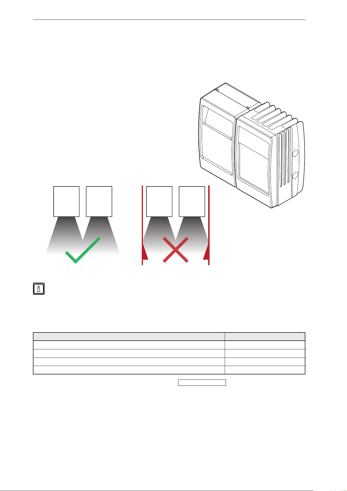
The mobile 3D sensor is operated as a system together with the illumination unit.
During installation note the following:
► Operate sensor and illumination unit in conjunction.
► Install sensor and illumination unit between 0 and 2.80 m
apart.
> Select the matching MCI connection cable depending on
the distance.
► Keep the area illuminated by the illumination unit free from
any obstructions in a close range (up to 50 cm)
(see figure below).
► Use cables with strain relief.
Sensor Illumination
unit
Sensor Illumination
unit
Further information about the electrical connection and the correct pin connection
→ Short instructions or operating instructions.
3.2 Mounting accessories
Depending on the intended mounting location and the type of installation, the following mounting
accessories are available:
Description Art. no.
Mounting set "U-tube" (u-shaped fixture with adjustment options for O3Mxxx housings) E3M100
Mounting set for rod mounting Ø 14 mm (clamp and bracket for O3Mxxx housings) E3M103
Rod, angled Ø 14 mm, length 130 mm, M12 E20939
Rod, angled Ø 14 mm, length 200 mm, M12 E20941
You can find more information about the accessories at:
8
www.ifm.com
Page 9
ifm Vision Assistant O3M
3.3 Software (ifm Vision Assistant)
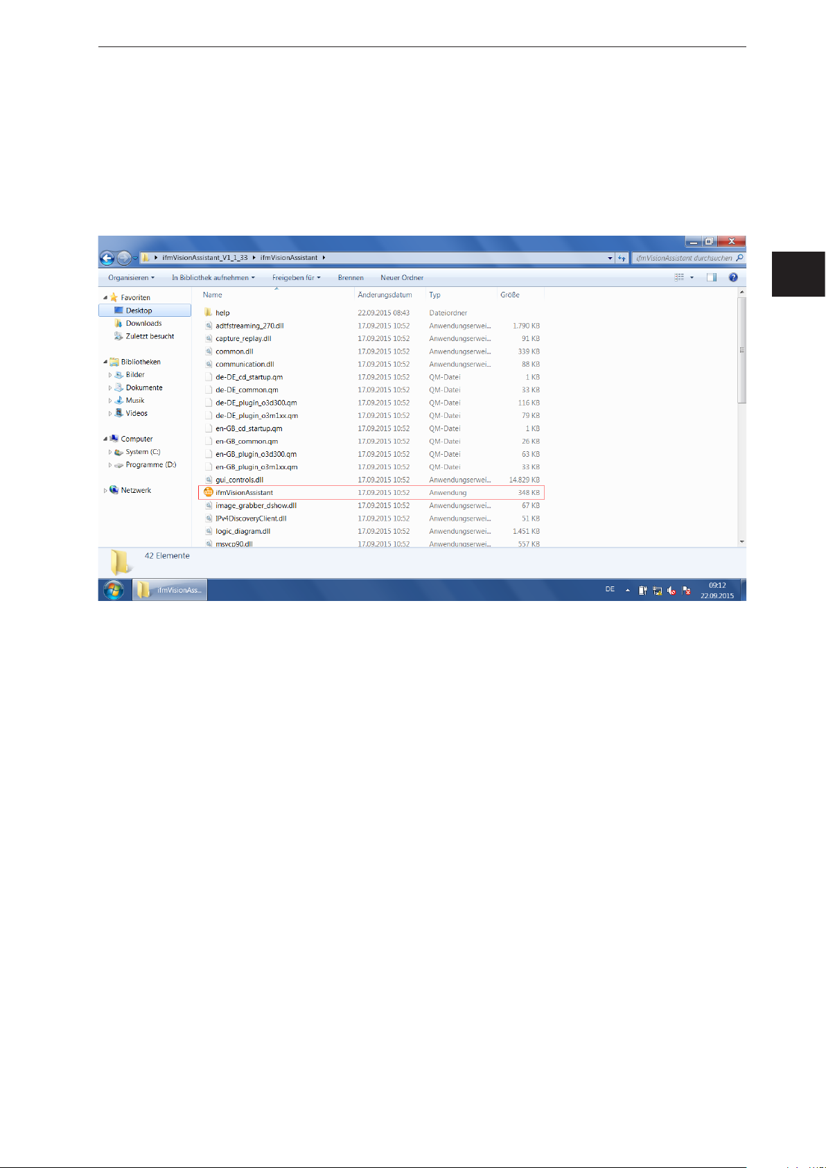
► Insert the data carrier with the ifm Vision Assistant software.
Alternative: Download ifm Vision Assistant software from the ifm website:
www.ifm.com → Service → Download
► Copy the Zip file "ifmVisionAssistant" into an appropriate directory on the PC and unzip.
► Start the "ifmVisionAssistant" application file.
UK
> The start page of the ifm Vision Assistant opens.
► If the start page does not appear after 5–10 seconds, please check if the software requirements are
complied with and if all files are properly unzipped.
9
Page 10
ifm Vision Assistant O3M
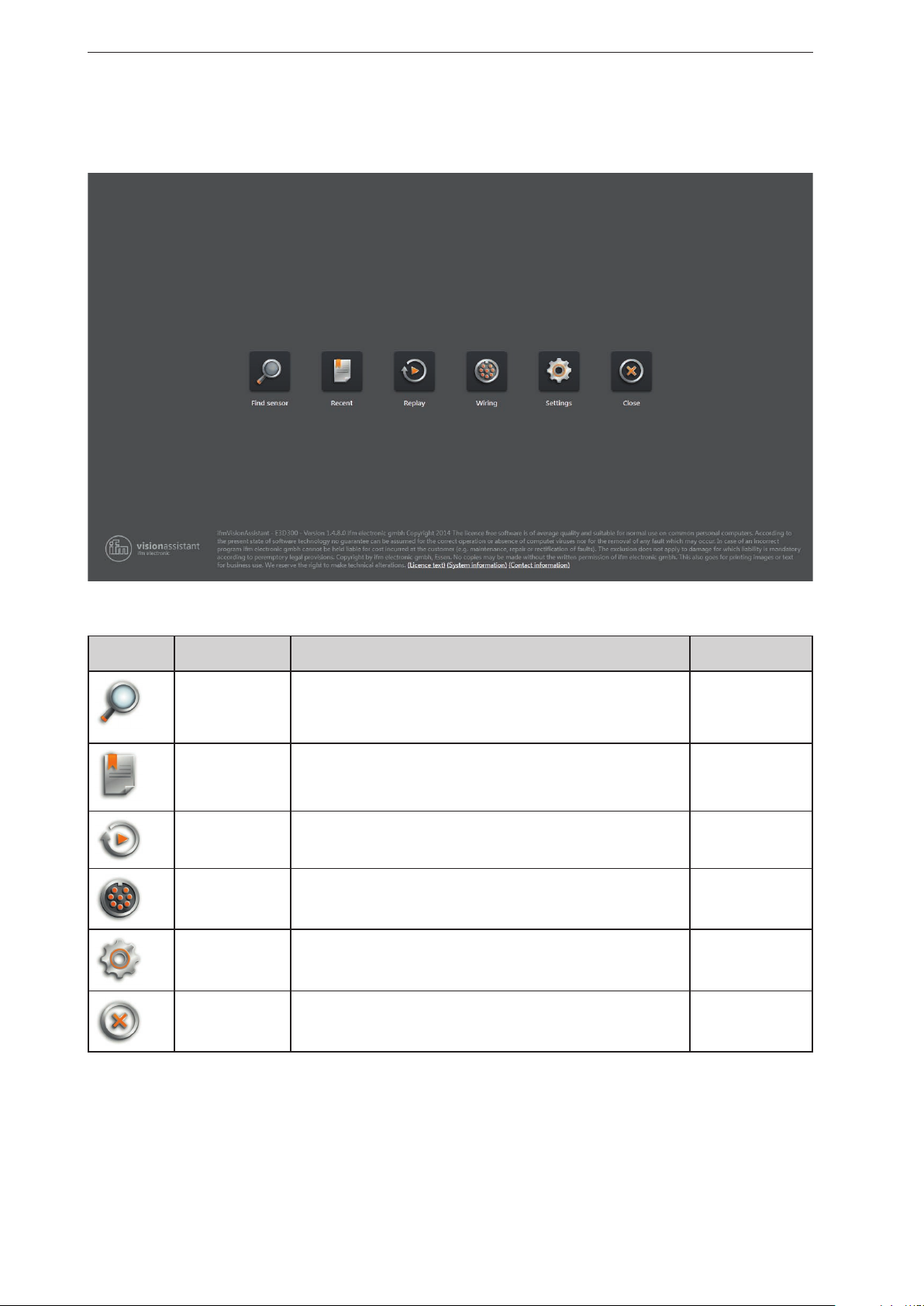
4 Start page
On the start page, the basic functions of the ifm Vision Assistant can be selected.
Basic functions of the start page:
Symbol name Function The device must
Find sensor Connection with the new added device.
Searches for connected devices and displays a selection list of the
devices found (→ „4.1 Find sensor“).
Recent Connection with the device that has connected itself successfully once
before.
Opens a selection list of the devices which have been connected
before (→ „4.2 Recent“).
Replay Plays recorded sequences (→ „4.3 Replay“). no
Wiring Display of the wiring of the voltage supply.
The display is used to simplify the connection during set-up
(→ „4.4 Wiring“).
Settings Language and image mode setting of the user interface
(→ „4.5 Settings“).
Close Quits the ifm Vision assistant. no
be connected
yes
yes
no
no
10
Page 11
ifm Vision Assistant O3M
4.1 Find sensor
With this function, it is possible to search for the connected devices or to establish a manual connection
with a connected device.
► Ensure that the device and the PC are ready for operation and that there is a CAN bus and Ethernet
connection.
> If the device is neither connected via CAN bus nor via Ethernet, only a restricted 3D visualisation is
possible and the connection is not automatically established.
> If the device is connected via Ethernet and not via CAN bus, no parameters can be written to the
device. Only monitoring is possible.
If possible, always connect the device both via CAN bus and Ethernet. Otherwise, functionality
is restricted. This documentation assumes that the device is connected via both CAN bus and
Ethernet.
The following ports must be open (if necessary, adjust the settings of the firewall):
● UDP: 42000
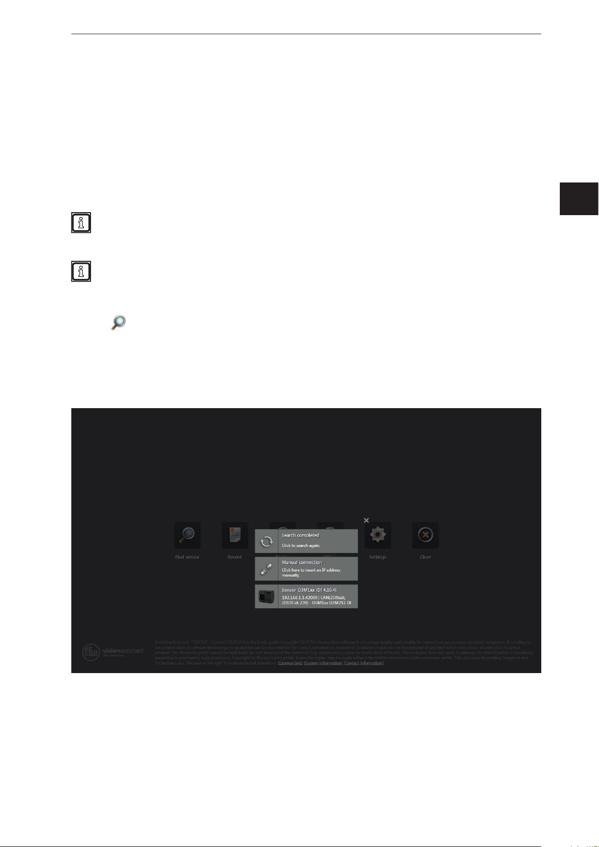
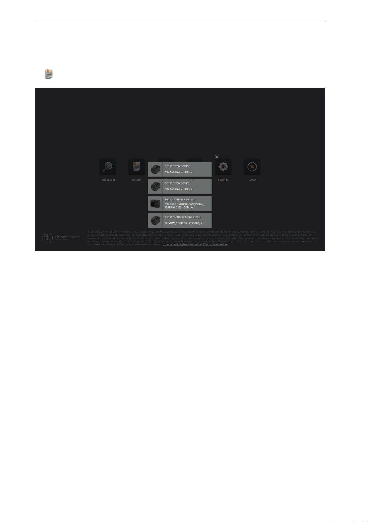
4.1.1 Direct search
UK
► Click .
> The ifm Vision Assistant searches for connected devices via the Ethernet connection.
> All devices found are shown in a list for selection. If there is a CAN bus connection, the CAN settings
are shown additionally.
► Click on the button of the found device in order to establish connection.
► If the ifm Vision Assistant does not find a device automatically:
● Check if the device is correctly connected and ready for operation and click on [Search completed]
to start a new search.
● Connect the device directly with the PC without any additional network devices in the connection
(e.g. router).
● Click on [Manual connection] and enter the connection settings manually
(→ „4.1.2 Manual connection“).
11
Page 12

ifm Vision Assistant O3M
Buttons and notifications after the direct search:
Button and notification Description
Starts a new search.
Makes it possible to enter the IP address manually (→ „4.1.2 Manual connection“).
Shows connection settings of the CAN bus such as IP address, name of the device and
the firmware version.
Connects the device and continues according to the application data.
12
Page 13
ifm Vision Assistant O3M
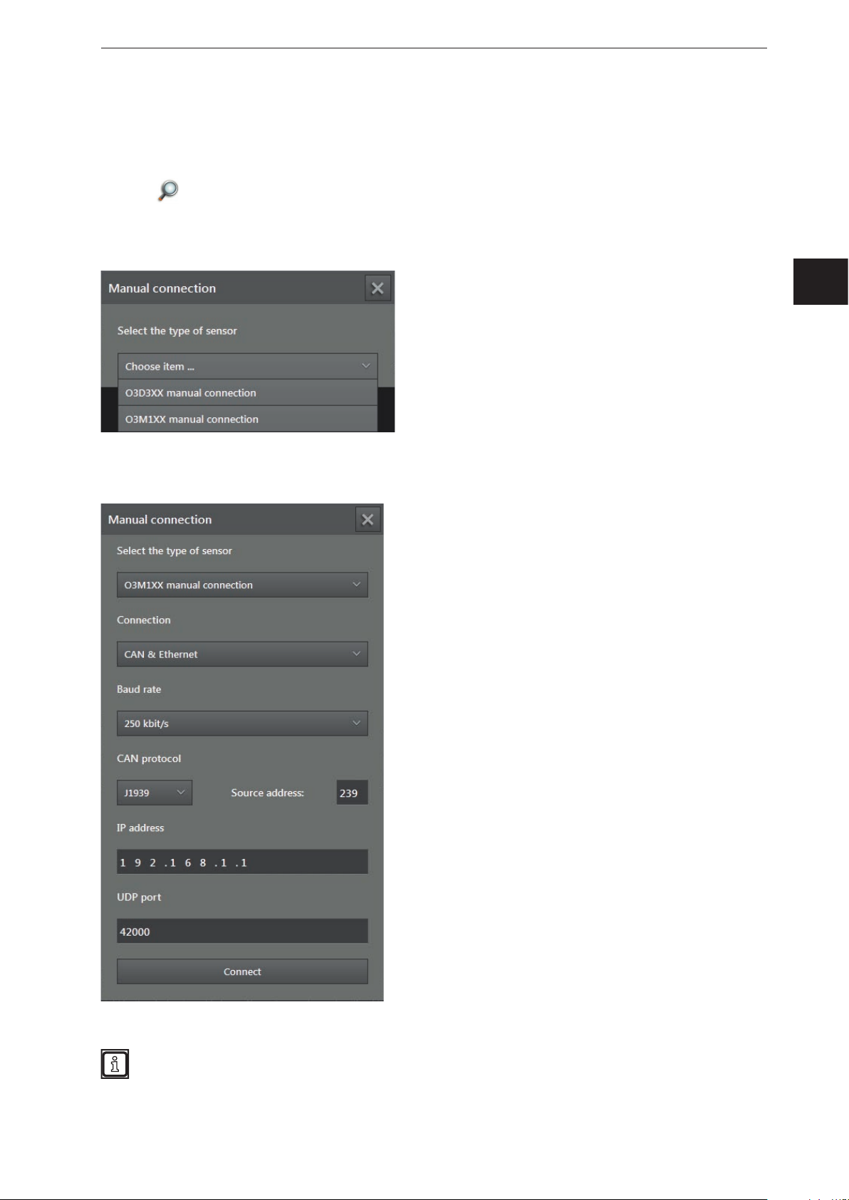
4.1.2 Manual connection
If the ifm Vision Assistant was not able to establish an automatic connection with the device, the
connection settings can be entered manually via the button [Manual connection].
► Click
► Click on [Manual connection].
> The "Manual connection" window is displayed:
► Select "O3M manual connection".
► Enter the IP address of the device (standard: 192.168.0.69).
.
UK
► Click on [Connect].
The IP addresses of device and PC with ifm Vision Assistant must be in the same subnet.
13
Page 14
ifm Vision Assistant O3M
4.2 Recent
This function opens a selection list of the devices that have already been connected.
Click .
►
► Ensure that the corresponding device is connected with the PC via Ethernet or available in the
network.
► Click on the device in the selection list.
> The ifm Vision Assistant establishes a connection with the device.
14
Page 15
ifm Vision Assistant O3M
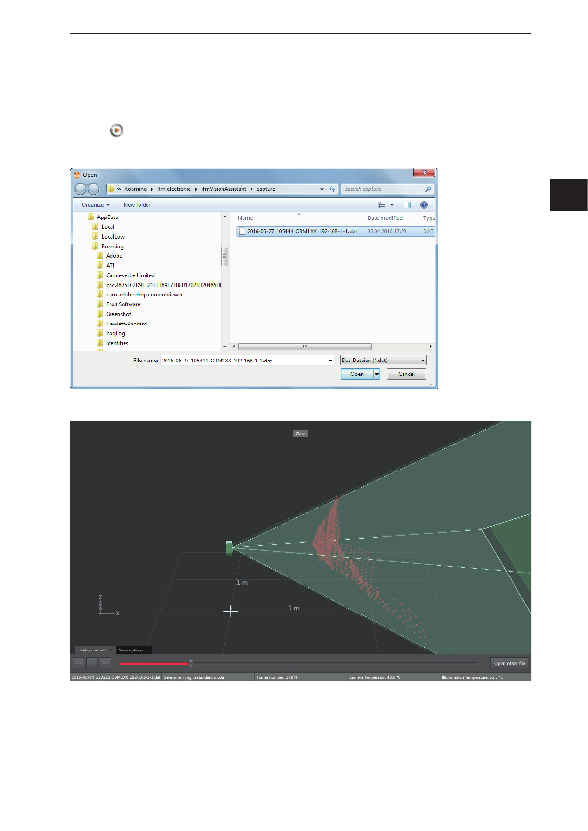
4.3 Replay
With this function, data that has been recorded can be viewed (→ „6 Monitoring window“). No connection
to a device is needed.
► Click
► Select the required file (*.dat) and click on [Open].
> The playback screen appears.
.
UK
15
Page 16

ifm Vision Assistant O3M
Options on the playback screen:
Tab Option / button Description
Replay
controls
View options – → „6.1 View Options“
–
pause
Down
Up
Start
Progress bar Indicates the current position in the recording.
Stops playback.
Stops playback and shows the previous picture.
Stops playback and shows the next picture.
Continues playback.
By clicking on a position in the progress bar, playback continues at the
corresponding image.
Opens a window in which a file can be selected.
Closes the playback screen and opens the start screen.
► Click on [Close] to return to the start screen.
16
Page 17
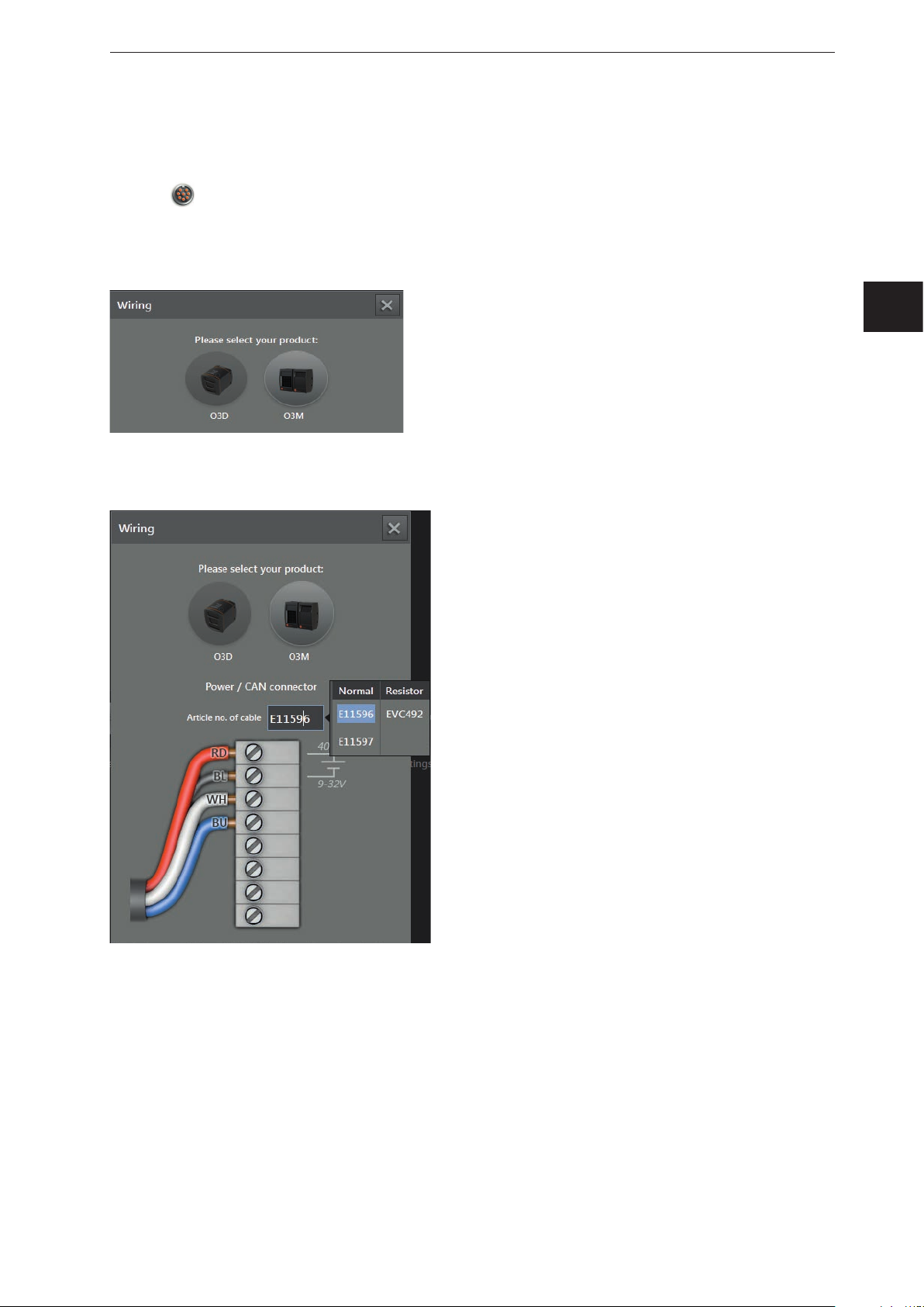
4.4 Wiring
This function allows correct wiring of the voltage supply of the 5-pole connector.
ifm Vision Assistant O3M
► Click
► Selected article [O3M].
> Only necessary if a new device has been selected.
► Click on the selection field [Article number] and select a connection cable from the selection list.
> For the selected cable, the wiring of the voltage supply and the CAN bus is shown.
.
UK
17
Page 18

ifm Vision Assistant O3M
4.5 Settings
You can use this function to change the language and to switch between full screen and window view.
► Click
.
> The "Settings" window is displayed.
Options in the settings window:
Field Option Description
Language English Selection of the available language.
German
etc.
Full screen
on
"English" is set by default.
Switches between full screen (on) and window view (off).
Full screen is set by default.
off
With the F11 key, you can switch between full screen and window view at any time.
4.6 Close
► Click on to quit the ifm Vision Assistant.
18
Page 19
5 Structure of the user surface
The screen of the ifm Vision Assistant has the following areas:
1. navigation bar:
In the navigation bar on the left, the required option can be selected
(→ „5.1 Navigation bar“).
2. main area:
The main area shows the selected option or application.
3. Status bar:
The status bar at the bottom of the screen shows the status information of the device.
ifm Vision Assistant O3M
UK
1: Navigation bar
2: Main area
3: Status bar
19
Page 20
ifm Vision Assistant O3M
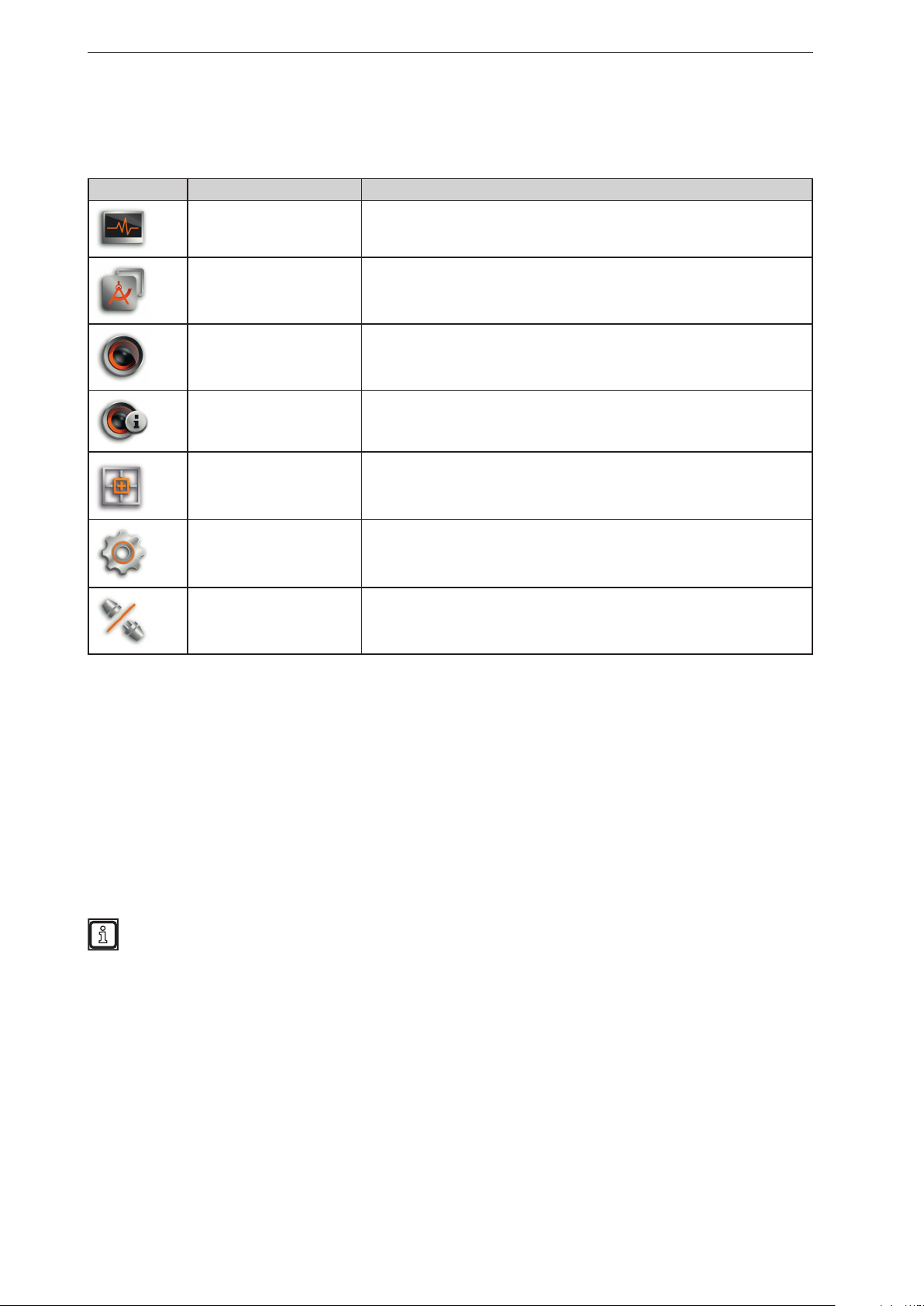
5.1 Navigation bar
The navigation bar on the left features the following options:
Button Name Description
Monitor
Applications
Device setup
Device information
Calibration Settings
Settings Opens the "Settings" window (→ „4.5 Settings“).
Disconnect
Opens a 2D or 3D view and shows the current device data
(→ „6 Monitoring window“).
Opens an overview of the applications (→ „11 2D overlay“).
Managing and adjusting the applications.
Opens the device setup (→ „11 2D overlay“).
For device settings that are independent of the applications.
Shows basic information (e.g. hardware firmware, device status) (→ „8 Device
Information“).
In the calibration settings, the device is calibrated for the intended application
(→ „9 Calibration settings“).
Disconnects the ifm Vision Assistant from the device.
The ifm Vision Assistant returns to the start screen.
5.2 Status bar
The status bar at the bottom of the screen gives the following information:
● Availability status
● Temperature information of the device, e.g. "Temperature normal"
● Connection type of the device, e.g. CAN and Ethernet
● Error mode of the device, e.g. xyz
● Frame count shows the number of frames
The availability status gives information about:
● Usability of the data
● Recognition of soiling (sensor disk dirty or frosted)
● Recognition of spray (can be activated in the programming mode)
5.3 Main area
While the device is operated, the main area shows the monitoring window
(→ „6 Monitoring window“).
When the device is being set up, the main area shows the corresponding screen pages.
20
Page 21
ifm Vision Assistant O3M
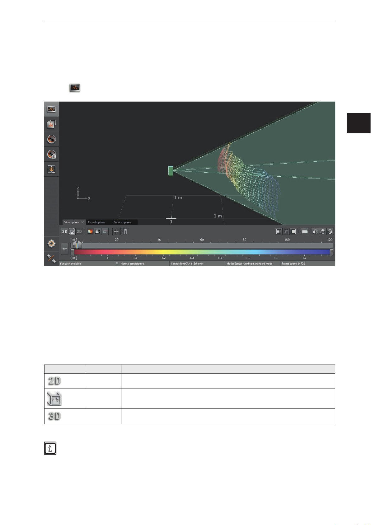
6 Monit oring window
The monitoring window is activated via the [Monitor] button. The unit is in the operating mode. In the
monitoring window, the running application can be monitored but neither interrupted nor changed.
Additionally, system and error information is indicated.
► Click
.
UK
Under the live image of the device, you see the following tabs:
● [View options] (→ „6.1 View Options“)
● [Record options] (→ „6.2 Recording“)
● [Service options] (→ „6.3 Service options“)
6.1 View Options
► Select options:
Button Name Description
2D view Shows the device data as a 2D visualisation (→ „6.1.1 2D View“).
2D3D view Shows the device data as 2D/3D visualisation (→ „6.1.2 2D3D view“).
3D view Shows the device data as a 3D visualisation (→ „6.1.3 3D view“).
The figures in the following chapters are examples. Depending on the objects and the individual
settings, the representation may differ significantly.
21
Page 22
ifm Vision Assistant O3M
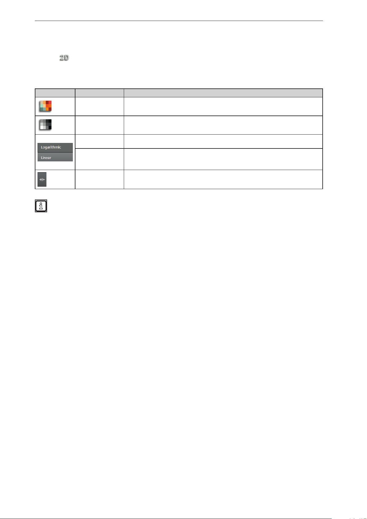
6.1.1 2D View
► Click to show the 2D view.
► Adjust the 2D view.
The following settings are available in the tab "View options":
Button Name Description
Distance image Visualises the pixels in the 2D view in relation to the distance values.
Amplitude image
Logarithmic
Linear
Rescaling
Visualises the pixels in the 2D view in relation to the amplitude values in levels of grey
(brightness).
Visualises the amplitude values of the 2D view in logarithmic levels of grey (only
available for the amplitude image).
Visualises the amplitude values of the 2D view in linear levels of grey (only available for
the amplitude image).
The "linear" view is particularly helpful when setting up the image.
Sets the colour range automatically to an adequate area. The settings of the slider bars
are dismissed.
The display settings (e.g. [Logarithmic] or [Linear]) only change the calculation and type of
visualisation. The application itself is not affected by it.
22
Page 23
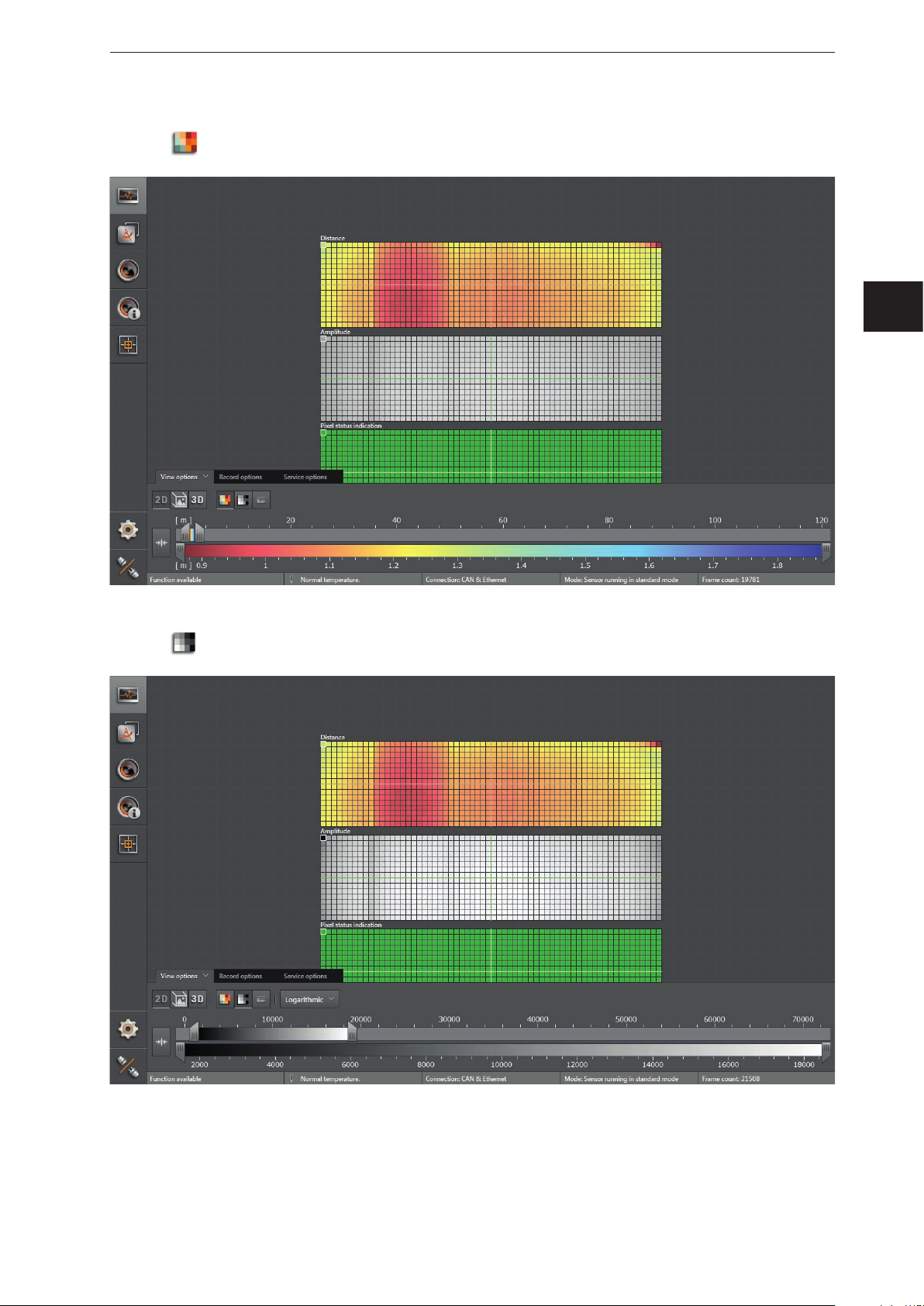
Distance image
ifm Vision Assistant O3M
► Click
to display the distance image.
UK
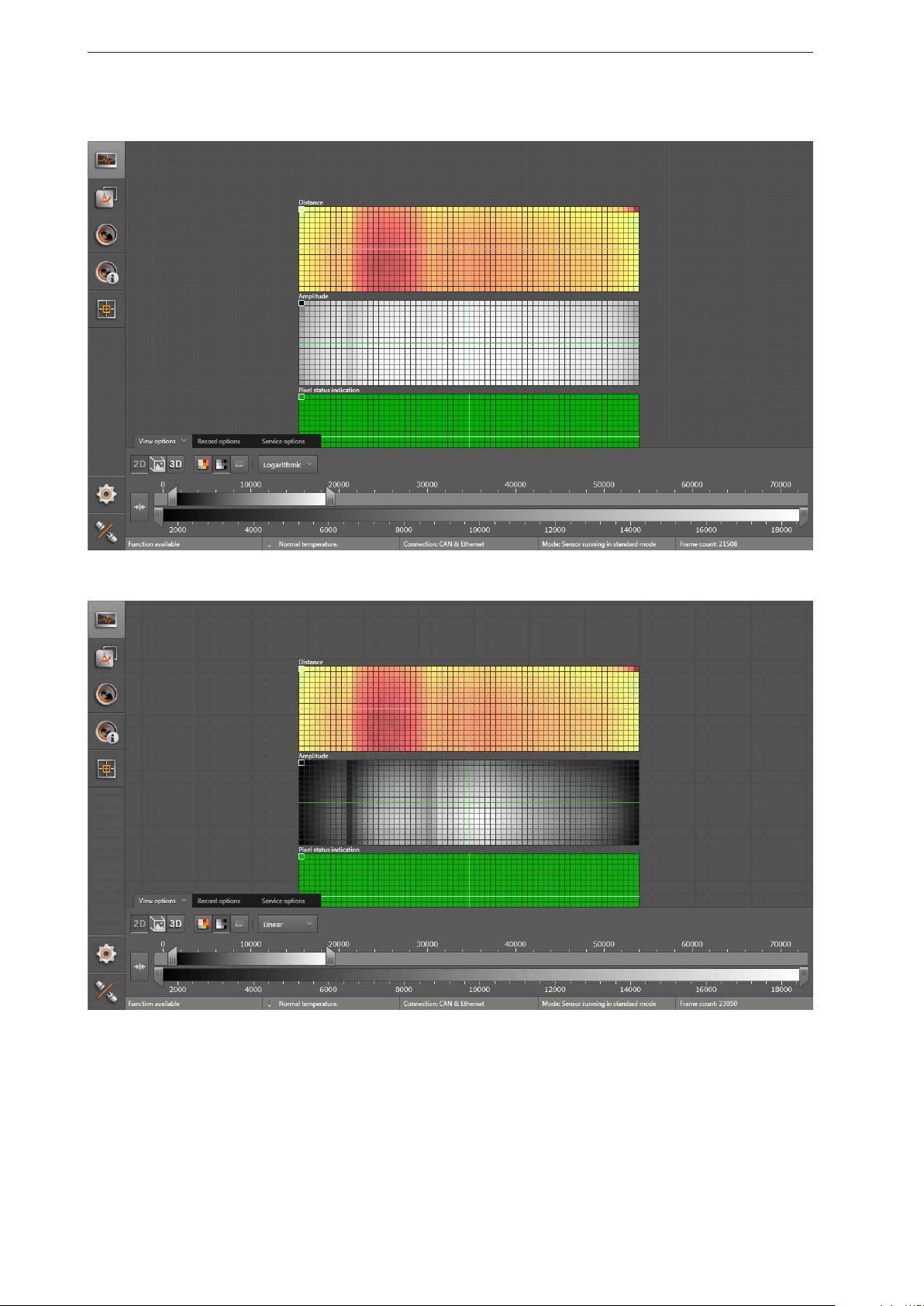
Amplitude image
► Click
to display the amplitude image.
► Select the required view via [Logarithmic] or [Linear].
23
Page 24
ifm Vision Assistant O3M
Logarithmic view:
Linear view:
24
Page 25
ifm Vision Assistant O3M
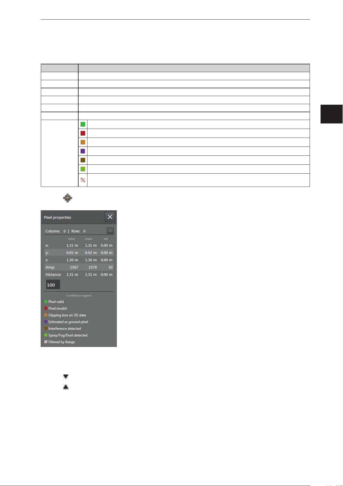
Pixel properties
Via this function, the following information about the selected pixel can be displayed:
Field Description
Column | Row Indicates the number of columns and rows of a pixel
x x coordinate of the pixel: current measured value and deviation (related to the world coordinate system)
y y coordinate of the pixel: current measured value and deviation (related to the world coordinate system)
z z coordinate of the pixel: current measured value and deviation (related to the world coordinate system)
Amplitude Amplitude of the pixel
Distance Distance of the pixel to the device
Valid pixel
Invalid pixel (signal too strong or too weak)
Spatially filtered 3D data (→ „10.11 Measuring range“)
Colour legend
Estimated as ground
Pixel detected as disturbed (interference can be produced by neighbouring O3Ms)
Spray / fog / dust detected
Filtered according to distance (if the pixel is outside the set distance, the ifm Vision Assistant is marked as
invalid. )
UK
► Click to open the "pixel properties" window.
► Click on the pixel in the 2D view.
> Position, amplitude and distance of the pixel are indicated in metres.
► Click
► Click
to open extended information.
to close extended information.
25
Page 26
ifm Vision Assistant O3M
6.1.2 2D3D view
The 2D3D view is only possible with the O3M2xx devices.
► Click
to show the 2D3D view.
► Adjust the 2D3D view.
The following settings are available in the tab "View options":
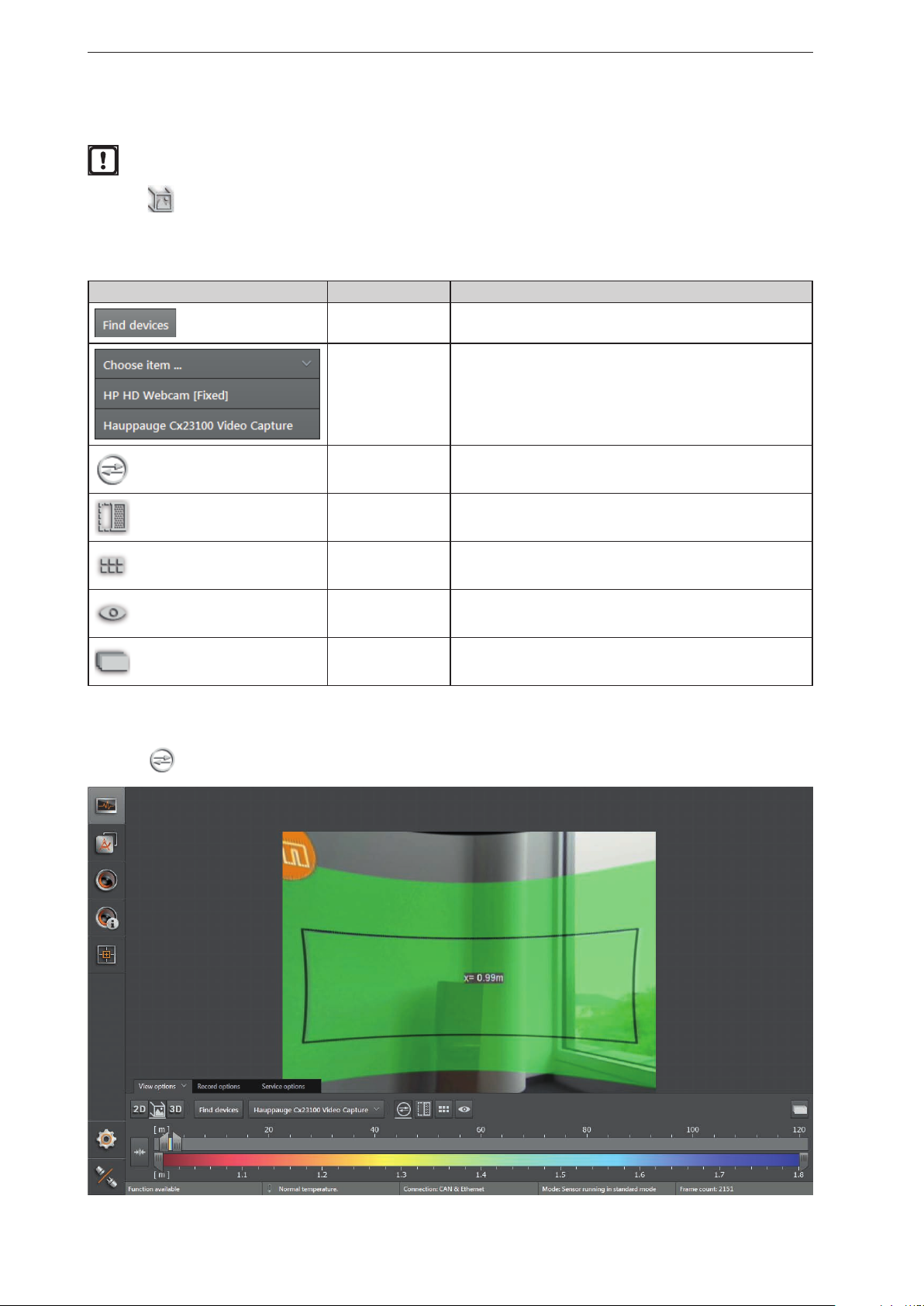
Button Name Description
Search for video
converter
Select video
converter
2D rectification Eliminates geometric distortions in the image data.
Spatially filtered 3D
data
Pixel Shows the distance values per pixel.
Visible 3D range Highlights the visible 3D range.
Searches for connected compatible video converters.
Connects a compatible video converter.
Shows the spatially filtered 3D data.
2D rectification
► Click
to activate the 2D rectification.
2D preview Shows the 2D data as an overlay within the 2D3D view.
26
Page 27
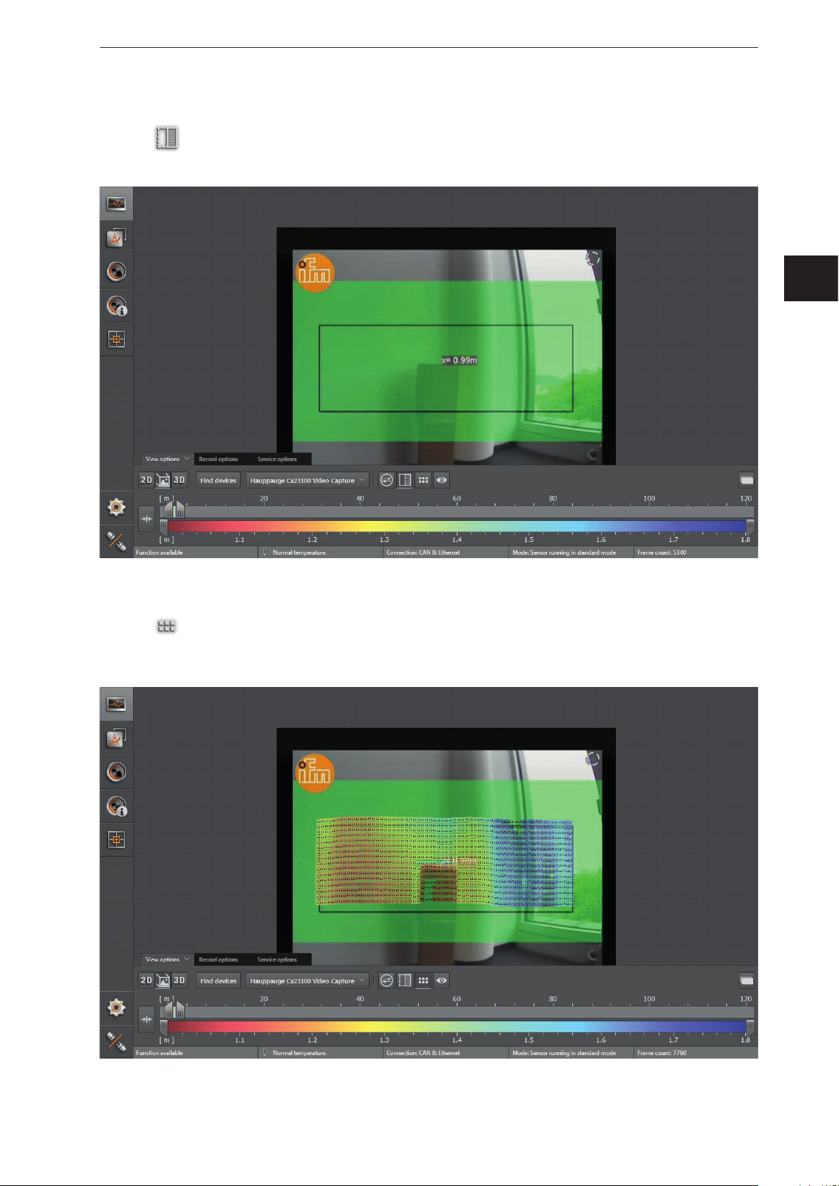
Spatially filtered 3D data
ifm Vision Assistant O3M
► Click
> Which 3D data is to be spatially filtered can be configured in chap. „10.11 Measuring range“.
to activate the spatially filtered 3D data.
UK
Pixel
► Click
> Each pixel contains the distance as a numeric value. The colour shade depends on the measured
distance of the pixel and the setting of the colour scale (→ „6.1.4 Slider bar“).
to display the distance values per pixel.
27
Page 28
ifm Vision Assistant O3M
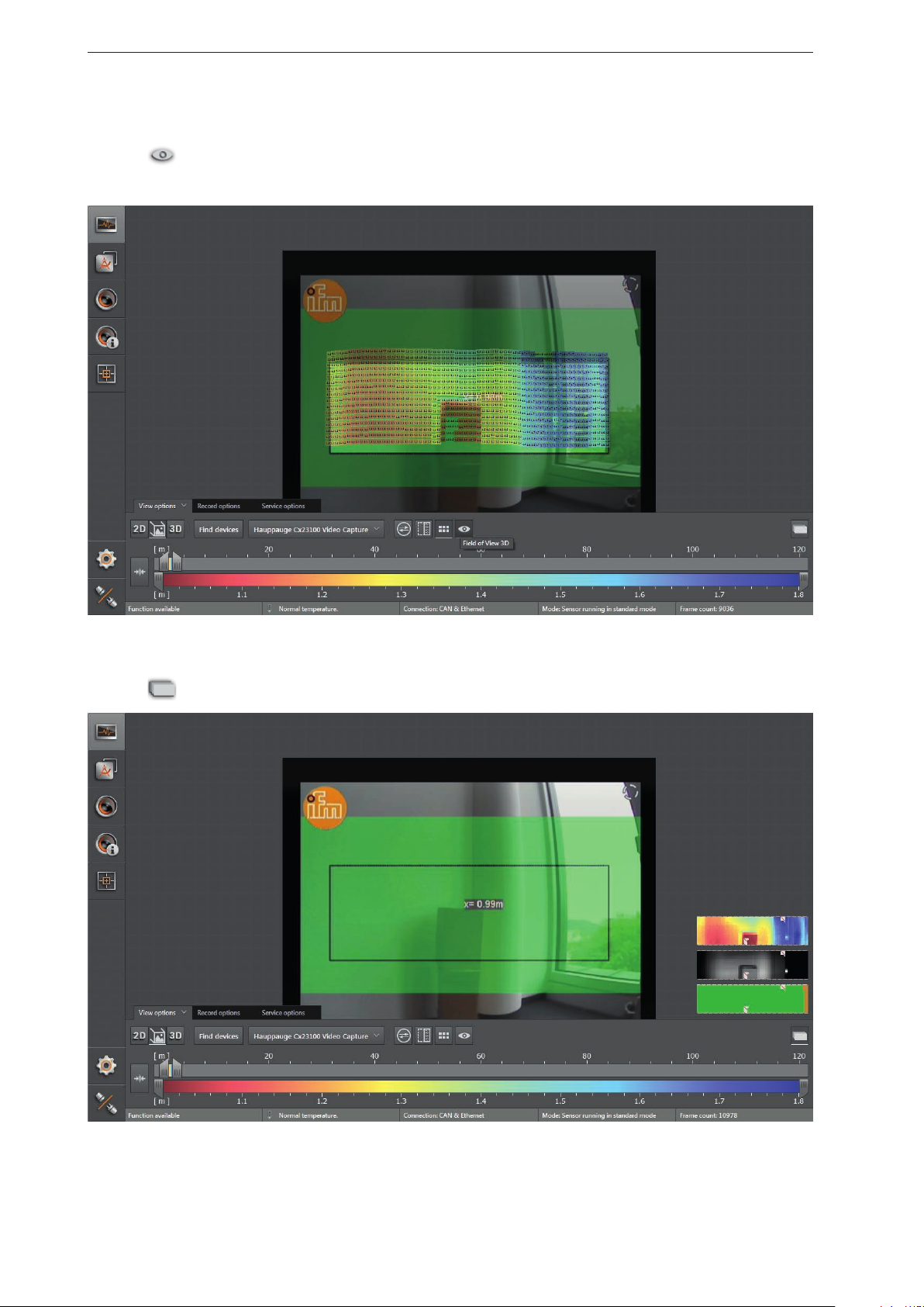
Visible 3D range
► Click
> The area outside the visible 3D range is visualised in a darker shade.
to activate the visible 3D range.
2D preview
► Click
to show the 2D data as an overlay within the 2D3D view.
28
Page 29
ifm Vision Assistant O3M
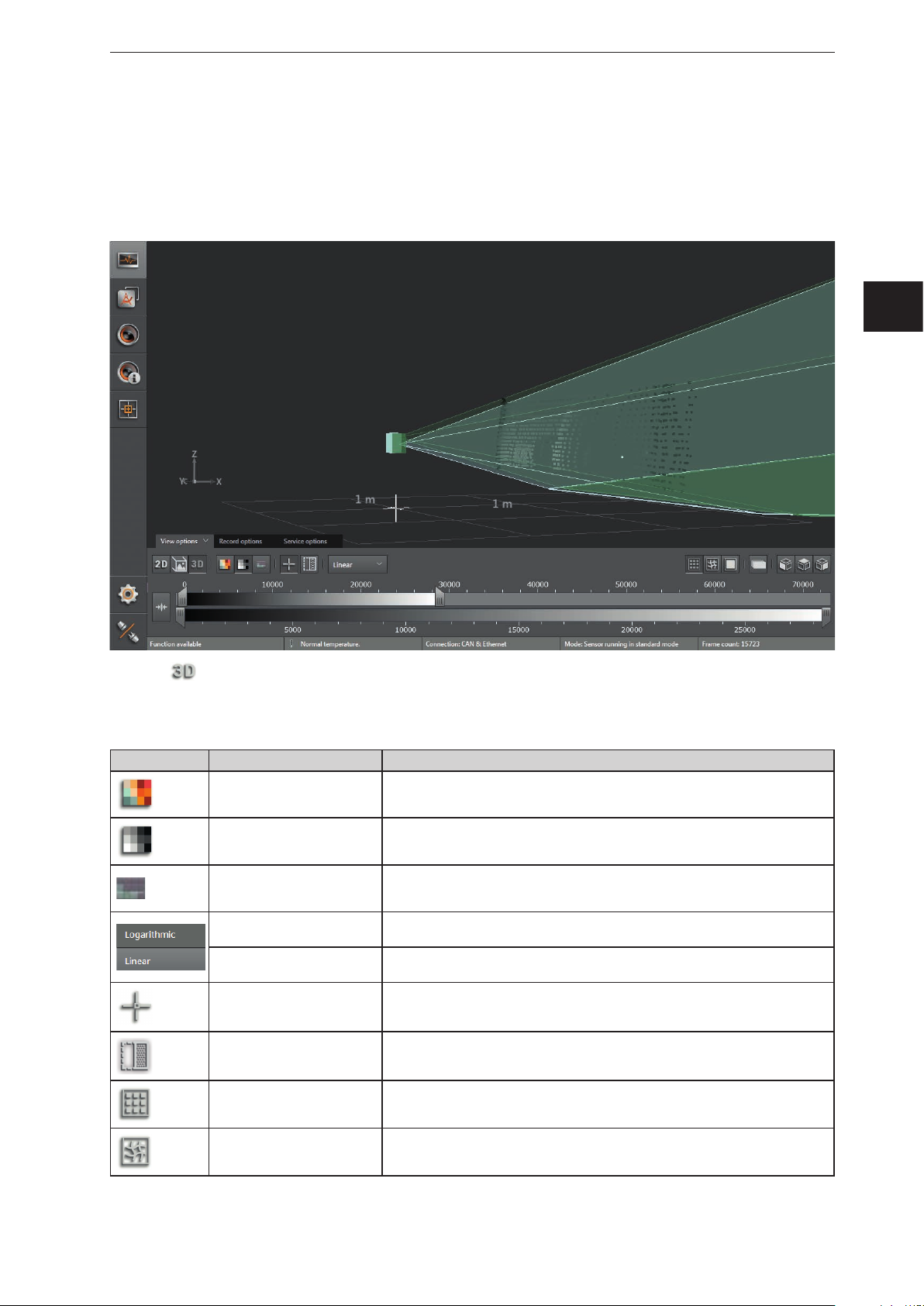
6.1.3 3D view
The 3D view is a visualisation of the 3D views of the device and the illumination unit. The individual vision
cones of the 3D views have different colours:
● Device: green
● Illumination unit: light green
UK
► Click to show the 3D view.
► Adjust the 3D view.
The following settings are available in the tab "View options":
Button Name Description
Distance image Visualises the pixels in the 3D view in relation to the distance values.
Amplitude image
Confidence
Logarithmic
Linear
Origin Shows and hides the origin of the coordinate system in the 3D view.
Spatially filtered 3D data Shows the spatially filtered 3D data.
Dots Shows the data as a pixel cloud.
Visualises the pixels in the 3D view in relation to the amplitude values in levels
of grey (brightness).
Shows the pixels of the 3D view with the corresponding status from the colour
legend (→ Pixel properties, previous page).
Visualises the amplitude values of the 3D view in logarithmic levels of grey (only
available for the amplitude image).
Visualises the amplitude values of the 3D view in linear levels of grey (only
available for the amplitude image).
Grid Shows the data as a grid.
29
Page 30
ifm Vision Assistant O3M
Button Name Description
Surface model Shows the ascending slopes as colour gradients.
2D preview Shows the 2D data as an overlay within the 3D view.
Default view 1 Turns the 3D view to the xy level.
Default view 2 Turns the 3D view to the xz level.
Default view 3 Turns the 3D level to the yz level.
The settings of the view (e.g. [Logarithmic] or [Linear]) only change the calculation and type of
visualisation. The application itself is not affected by it.
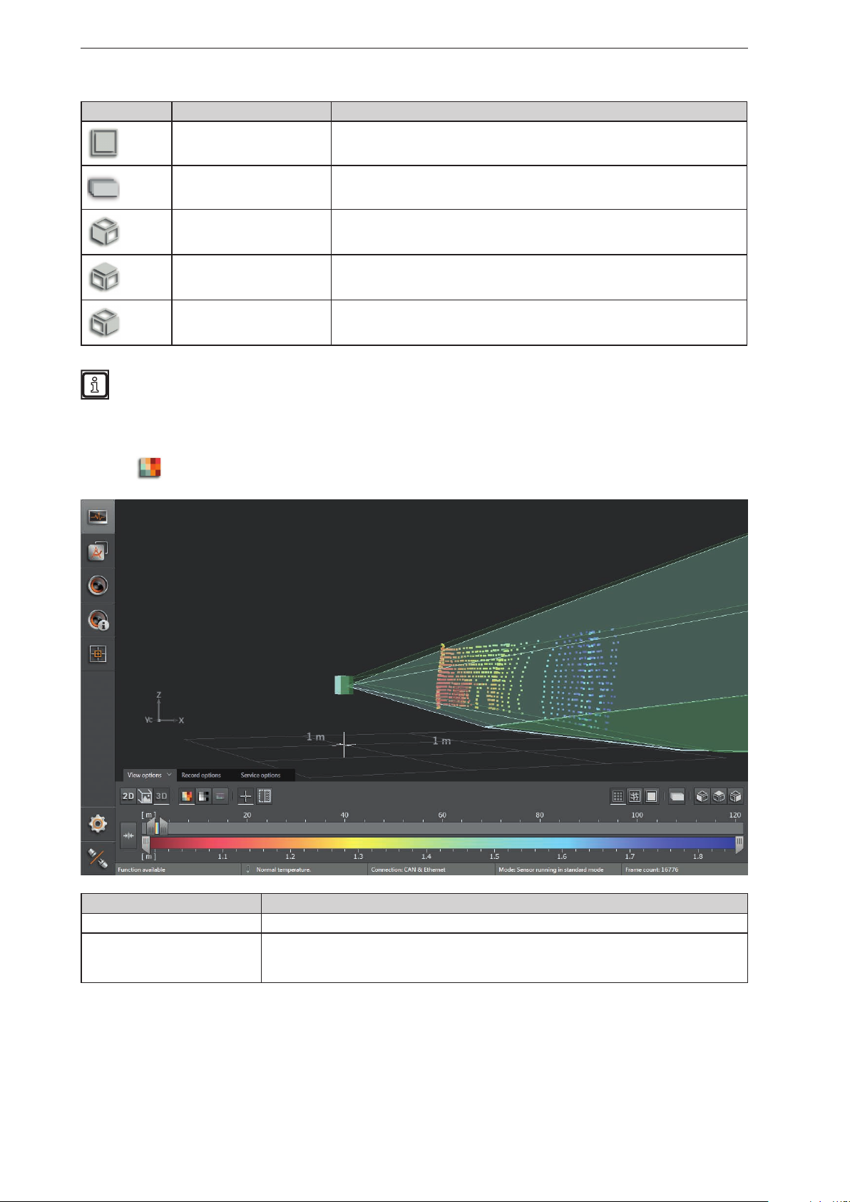
Distance image
► Click
to display the distance image.
Visualisation in the 3D image Description
Pixel position Space coordinate of the point (x, y, z coordinates).
Distance (x-coordinate).
Pixel colour
The colour shade depends on the measured distance of the point and the setting of the colour
scale (→ „6.1.4 Slider bar“).
30
Page 31

Amplitude image
ifm Vision Assistant O3M
► Click
to display the amplitude image.
UK
► Select the required view via [Logarithmic] or [Linear].
Visualisation in the 3D image Description
Pixel position Space coordinate of the point (x, y, z coordinates).
Amplitude value.
Pixel colour (grey-scale)
Black Amplitude value ≤ minimum of the set scale.
White Amplitude value ≥ maximum of the set scale.
The brightness follows the measured amplitude and the setting of the grey scale (→ „6.1.4
Slider bar“).
31
Page 32

ifm Vision Assistant O3M
Views in the coordinate system
The 3D view can be turned into a preset view in the coordinate system.
► Click
> The object is shown on the yz level.
to show the rear view.
► Click to show the top view.
> The object is shown on the xy level.
32
Page 33

► Click to show the side view.
> The object is shown on the xz level.
ifm Vision Assistant O3M
UK
Visualisation pattern
► Click
to show the 3D view as a pixel cloud.
33
Page 34

ifm Vision Assistant O3M
► Click to show the 3D view as a grid.
► Click to show the ascending slopes in the 3D view as a surface model.
34
Page 35

ifm Vision Assistant O3M
6.1.4 Slider bar
With the slider bar, the colour range of the display can be set manually. The results of the application are
not changed by it.
● Distance image: Measuring range in metres (from-to)
● Amplitude image: Measuring range in amplitudes (from-to)
Setting the colour range
Operating element Description
Automatic
range
selection
Upper
slider bar
Lower
slider bar
Colour range
The button sets the colour range automatically to an appropriate area. The settings of the slider
bars are dismissed.
With the upper slider bar, the colour range for the distance or amplitude image can be roughly
set.
With the lower slider bar, the set colour range can be fine-adjusted.
The set colour range can be shifted using the left mouse button without changing the size of the
range.
The vertical white lines within the colour range indicate the colour range that is fine-adjusted
with the lower slider bars.
► The upper slider bar can be set to the required colour range.
► Set the lower slider bar to fine-adjust the colour range.
> The scale of the lower slider bar corresponds with the colour range that is set above.
UK
35
Page 36

ifm Vision Assistant O3M
6.2 Recording
This function is used to make recordings of any length of Ethernet and CAN data.
► Select the duration of the recording in the "Record options" tab (1, 2, 4, 8 minutes or infinite duration).
The space required is about 56 MB/minute (with debug data approx. 160 MB/minute).
► Click
► Click
> The debug data is necessary to analyse service requests.
► Click
> The "Save As" window opens with a standard storage location and standard file name:
● Standard storage location: "…\ifm electronic\ifmVisionAssistant\capture" (the exact and complete
● Standard file name: "yyyy-mm-dd_hhmmss_O3M1XX_192-168-1-1.dat"
> All measurement and process data is recorded (e.g. recognised objects and results of the
applications).
to start a recording.
to additionally record debug data.
to additionally record the CAN data.
storage location depends on the Windows version and settings)
The file name consists of year, month, day and the IP address of the device.
Example: The file "2016-06-27_154754_O3M1XX_192-168-1-1.dat" was recorded on 27 June
2016 at 15:47:54 on the device with IP address 192.168.1.1.
36
Page 37

ifm Vision Assistant O3M
UK
► Click [Save].
> The recording starts and the recorded time is displayed next to the
Example: 1 minute and 5 seconds of the set 2 minutes are displayed as 01:05/02:00.
> The recording ends automatically as soon as the set recording time is reached. In case the duration is
set to "infinite", the recording is limited by the free memory capacity of the data carrier.
button.
► Click again to manually stop the recording before the set recording duration is reached.
> The sequence is stored and can be played back using the [Replay] option on the start screen.
37
Page 38

ifm Vision Assistant O3M
6.3 Service options
Via the service options function, the error memory and the system overview can be displayed. The
service options contain software and hardware information that can be displayed and stored.
The error memory and the system overview are used to analyse service requests.
Error memory export
► Click on [Show error memory].
► Click on [Export error memory].
> The error memory is stored as text format (*.txt).
38
Page 39

Show system overview
► Click on [Show system overview].
> The "System status" window appears.
ifm Vision Assistant O3M
UK
► Click on [Export system status] to save the system overview.
► Click on [X] to close the system overview.
39
Page 40

ifm Vision Assistant O3M
7 Device setup
In the device setup, the basic settings of the device and the applied networks is set.
► Click
> The "Device setup" screen appears.
Configurations in the device setup:
● Device (→ „7.1 Device“)
● Set the name of the device
● Execute the assistant for general sensor settings
● Execute firmware update
● Import and export settings
● Reboot the sensor
● Activate online parameter setting
● CAN settings (→ „7.2 CAN settings“)
● Set the network protocol and the network address of the CAN bus
● Ethernet (→ „7.3 Ethernet“)
● Set the process interface
.
40
Page 41

7.1 Device
In the "Device" window, basic settings of the device can be made.
► Click on [Device].
> The "Device" window appears.
Functions
Field Button Description
Name – Editable field to set the device name
General settings
wizard
firmware update [Update]
Import / Export
Reboot the sensor [Reboot sensor] Reboots the device.
[Start] Starts the assistant for general sensor settings
Installs a firmware update.
The current version of the firmware is shown next to the button.
[Export] Creates a copy of the settings and applications on the PC.
[Import] Saves a copy of the settings and applications that are on the PC to the device.
7.1.1 Name
The name of the device can be edited at will.
ifm Vision Assistant O3M
UK
► Click on the input box.
► Enter name.
► Click
to save the changes.
7.1.2 General settings wizard
The "General settings wizard" adjusts the device to the corresponding application. At the beginning, the
assistant retrieves basic settings about the application of the device. At the end, the device is set by the
assistant.
► Click on [Start].
> The general settings wizard appears.
The general settings wizard starts automatically after flashing a firmware (→ „7.1.3 Firmware
update“).
41
Page 42

ifm Vision Assistant O3M
► Click on [Start].
42
Page 43

Button Name Description
Use the setting "stationary" for the installation on:
● stationary vehicles
● objects
Stationary
● moving vehicles that are stationary during device operations
With the setting "stationary", higher averaging settings can be used (→
„10.9 Intelligent data averaging“).
ifm Vision Assistant O3M
Moving vehicle
Use the "vehicle" setting for installation on moving vehicles (→ „The "moving
vehicle" setting“).
► Click on [stationary] or [moving vehicle].
> The [moving vehicle] setting requires additional settings.
► Click on [Next].
"Stationary" setting
In the following, the general setting "stationary" is described.
UK
Button Name Description
Set the frame rate of the device according to the ambient temperature:
● 85°C: Frame rate of 25 Hz
● 75°C: Frame rate of 33 Hz
Ambient temperature
● 65°C: Frame rate of 50 Hz
Always use the highest possible frame rate.
43
Page 44

ifm Vision Assistant O3M
Button Name Description
Use the "Outdoors" setting if strong environmental influences are to be
expected in the application. The setting affects the:
● Filter signal quality (→ „10.3 Signal quality filter“)
● Noise reduction filter (→ „10.4 Noise reduction filter“)
Application
Use the "Indoors" setting if insignificant environmental influences are to be
expected in the application. The setting affects the:
● Filter signal quality (→ „10.3 Signal quality filter“)
● Noise reduction filter (→ „10.4 Noise reduction filter“)
Activate the "Visibility conditions" setting if the visibility conditions are
often bad. The setting affects the:
● Filter signal quality (→ „10.3 Signal quality filter“)
Visibility conditions
Detection of soiling
● Spray detection (→ „10.5 Detection of spray/fog/dust“)
Dusty and foggy environmental conditions require stronger data
filtering. The "Visual conditions" setting reduces the device's
range.
Setting the sensitivity of the soiling detection:
The setting affects the: Soiling detection
(→ „10.6 Soiling detection“).
► Click on [Next].
Slider bar Name Description
Set the speed of the objects that are detected by the
Typical object
speed
device using the slider bar "Typ. object speed". The
setting improves the data quality.
The setting affects the: Intelligent data averaging (→
„10.9 Intelligent data averaging“).
► Click on [Next].
44
Page 45

ifm Vision Assistant O3M
The result settings affect the connection of the device within the application.
The connection settings between ifm Vision Assistant and the device are described in chapter
„4.1.2 Manual connection“.
Button Name Description
Use the "CAN" setting if the measurement results of the
application are transferred via CAN.
Using the results
Repetition rate
Results via
Ethernet
Use the "Ethernet" setting if the measurement results of the
application are transferred via Ethernet.
Use the "CAN & Ethernet" setting if the measurement results
of the application are transferred via CAN and Ethernet.
The setting determines the repetition rate of the data. A high
repetition rate increases the data flow-rate.
The repetition rate of the data depends on the ambient
temperature
(→ Seite 43, image settings - environment).
The setting affects the: Data refresh to CAN / Ethernet in
relation to the sensor cycle (→ „7.2 CAN settings“) / (→ „7.3
Ethernet“).
The "Only function results" setting sends object data and ROI
results via Ethernet (no 3D pixel data). The setting reduces
the data flow-rate via Ethernet.
The setting "All results (full 3D data + functional results)"
sends 3D pixel data, object data and ROI results via
Ethernet. The setting increases the data flow-rate via
Ethernet.
UK
► Click on [Next].
45
Page 46

ifm Vision Assistant O3M
The "moving vehicle" setting
In the following, the general setting "moving vehicle" is described.
Button Name Description
Set the speed of the vehicle.
The setting affects the: Intelligent data averaging (→ „10.9
Vehicle speed
Object speed
Several vehicles
Intelligent data averaging“).
In case of high vehicle speeds, it is recommended
to reduce the value of the intelligent data averaging
(→ „10.9 Intelligent data averaging“).
Setting the speed of the objects.
The setting affects the: Intelligent data averaging (→ „10.9
Intelligent data averaging“).
In case of high object speeds, it is recommended
to reduce the value of the intelligent data averaging
(→ „10.9 Intelligent data averaging“).
If several vehicles with devices move in the working area,
this may produce measurement errors.
The "Yes" setting applies random modulation frequencies for
the devices.
The "Yes" setting affects the: Modulation frequency mode
(→ „10.8 Modulation frequency mode“)
The setting "no" affects: Intelligent data averaging (→ „10.9
Intelligent data averaging“)
► Click on [Next].
46
Page 47

ifm Vision Assistant O3M
UK
Button Name Description
Set the frame rate of the device according to the ambient temperature:
● 85°C: Frame rate of 25 Hz
● 75°C: Frame rate of 33 Hz
Ambient temperature
Application
Visibility conditions
Detection of soiling
● 65°C: Frame rate of 50 Hz
Always use the highest possible frame rate.
Use the "Outdoors" setting if strong environmental influences are to be
expected in the application. The setting affects the:
● Filter signal quality (→ „10.3 Signal quality filter“)
● Noise reduction filter (→ „10.4 Noise reduction filter“)
Use the "Indoors" setting if insignificant environmental influences are to be
expected in the application. The setting affects the:
● Filter signal quality (→ „10.3 Signal quality filter“)
● Noise reduction filter (→ „10.4 Noise reduction filter“)
Activate the "Visibility conditions" setting if the visibility conditions are
often bad. The setting affects the:
● Filter signal quality (→ „10.3 Signal quality filter“)
● Spray detection (→ „10.5 Detection of spray/fog/dust“)
Dusty and foggy environmental conditions require stronger data
filtering. The "Visual conditions" setting reduces the device's
range.
Use the setting "Soiling detection" to set the sensitivity of the soiling
detection:
The setting affects the: Soiling detection
(→ „10.6 Soiling detection“).
► Click on [Next].
47
Page 48

ifm Vision Assistant O3M
The result settings affect the connection of the device within the application.
The connection settings between ifm Vision Assistant and the device are described in chapter
„4.1.2 Manual connection“.
Button Name Description
Use the "CAN" setting if the measurement results of the
application are transferred via CAN.
Using the results
Repetition rate
Use the "Ethernet" setting if the measurement results of the
application are transferred via Ethernet.
Use the "CAN & Ethernet" setting if the measurement results
of the application are transferred via CAN and Ethernet.
The setting determines the repetition rate of the data. A high
repetition rate increases the data flow-rate.
The repetition rate of the data depends on the ambient
temperature
(→ Seite 43, image settings - environment).
The setting affects the: Data refresh to CAN / Ethernet in
relation to the sensor cycle (→ „7.2 CAN settings“) / (→ „7.3
Ethernet“).
► Click on [Next].
48
Page 49

ifm Vision Assistant O3M
UK
► Click on [Ready].
> The setting of the device via the assistant "General sensor settings" is finished.
49
Page 50

ifm Vision Assistant O3M
7.1.3 Firmware update
The current firmware is on the supplied data carrier or can be downloaded from the internet if needed:
www.ifm.com → Service → Download
The DI firmware is installed by default on the device. The following firmware is currently available:
● DI - Basic functions (standard firmware)
● OD - Object detection and collision avoidance
● LG - Line guidance
All settings and applications will be deleted when the firmware is updated.
► Export the settings before the firmware update.
► Click on [Refresh] to update the firmware.
> A safety query is displayed.
► Click on [Ok].
> The "Open" window appears.
► Select the required firmware file (*.fcr).
► Click on [Open].
> The firmware is being updated. After that, the ifm Vision Assistant re-establishes the connection to the
device.
After the firmware update, the following window appears:
Start the assistant by clicking on [Ok] in order to adjust the settings for the corresponding applications.
Error messages
Error message Solution
If the connection to the device is interrupted during a firmware
update, this error message appears.
►Restore the firmware via the manual connection (→ „4.1.2
Manual connection“).
50
If the connected device of the illumination unit is compatible
with the firmware, the error message below appears.
►Use a different firmware version or compatible hardware.
Page 51

ifm Vision Assistant O3M
7.1.4 Export settings
With the "Export" function, all settings and applications are exported from the device to the PC.
► Click on [Export] to start the export of the settings.
> The "Save As" window appears.
UK
► Enter the name and click on [Save].
> The settings will be saved to a file with the extension .o3m1xxcfg.
7.1.5 Import settings
With the "Import" function, the settings and applications are imported from the OC to the device.
Existing settings and applications are overwritten during the import.
► If necessary, export the existing settings beforehand.
► Click on [Import] to start the import of the settings.
51
Page 52

ifm Vision Assistant O3M
> The "Open" window appears.
► Select the required file with the ending .o3m1xxcfg and click on [Open].
> The settings will be imported.
7.1.6 Reboot the sensor
The device can be rebooted using the [Reboot sensor] button.
► Click on [Reboot the sensor].
> The device reboots.
> The ifm Vision Assistant establishes a new connection with the device.
► If the new connection to the device fails, search the device via
manually.
on the start screen or connect it
52
Page 53

ifm Vision Assistant O3M
7.1.7 Online parameter setting
With the [Online parameterisation] switch, the online parameter setting of the device is activated.
When "online parameterisation" is activated, changed parameters will be immediately written to the
device. The changes are visible within a very short time (real-time).
The changes are written in a volatile partition of the RAM and are lost e.g. when the device is
rebooted.
UK
► Save the changes permanently by clicking on
If "online parameterisation" is deactivated, changed parameters are only written after clicking on
[Save]. The changes are stored in a non volatile partition of the RAM and will be visible after approx. 15
seconds.
"Online parameterisation" is deactivated by default.
"Online parameterisation" can be used by controllers (CAN controllers). Adequate libraries are
available for ifm mobile controllers with CAN input
(→ „16.3 Connect O3M to external devices“).
[Save].
53
Page 54

ifm Vision Assistant O3M
7.2 CAN settings
In the "CAN settings" window, different parameters of the CAN bus can be set.
► Click on [CAN settings].
> The "CAN settings" window appears.
Functions
Field Description
Selection menu to set the CAN protocol:
CAN protocol
Selection menu to set the baud rate:
Select baud rate
Editable field to set data refreshing via the CAN bus. Frequent refreshing utilises more CAN bus capacity
Refresh rate on
CAN relating to
frame rate of
sensor
Source address
Node ID
which may slow down response times. The following refresh rates can be set:
● 1: Each image of the device updates the data via the CAN bus (high CAN bus capacity utilisation)
● 2: Every second image of the device refreshes the data via the CAN bus
● 3: Every third image of the device refreshes the data via the CAN bus
● 4: Every fourth image of the device refreshes the data via the CAN bus
● 5: Every fifth image of the device refreshes the data via the CAN bus (low CAN bus capacity utilisation)
Editable field to set the source address. Default value is "239". The field is only visible if the CAN protocol
"J1939" is set.
Editable field to set the node ID, default value is "10". The field is only visible if the CAN protocol "CANopen"
is set.
54
Page 55

Field Description
Selection menu to set the behaviour of several sensors on one CAN bus.
ifm Vision Assistant O3M
Synchronisation
of several
sensors on one
CAN
To synchronise several devices, one device is set as "Exposure Master". The Exposure Master sends sync
messages to further devices.
Further devices are set as "Exposure slave 2 (time shifted)" or "Exposure slave 1 (simultaneous)" The devices
receive the sync messages of the Exposure Master and synchronise themselves correspondingly.
►Set further devices as "Exposure slave 1 (simultaneous)" if the fields of view of the devices do not overlap.
►Set further devices as "Exposure slave 2 (time shifted)" if the fields of view of the devices do not overlap.
It is possible to synchronise several units on one CAN bus if the following points apply:
● The CAN protocol "J1939" is set.
● The frame rate is set to 25 Hz or 33 Hz.
● The Exposure Master has source address "239".
To ensure that the synchronisation is as error-free as possible, it is recommended to set up a separate CAN
bus for the devices.
7.3 Ethernet
In the "Ethernet" window, the network settings of the device are changed.
► Click on [Ethernet].
> The "Ethernet" window appears.
UK
55
Page 56

ifm Vision Assistant O3M
Functions
Field Description
IP address Editable field to set the IP address of the device. Default value is "192.168.1.1".
Subnet mask Editable field to set the subnet mask. Default value is "255.255.255.0".
IP destination Editable field to set the IP address of the receiver. Default value is "255,255,255,255".
UDP port Editable field to set the UDP port. Default value is "42000".
Editable field to set the data update via Ethernet. Frequent refreshing utilises more Ethernet
capacity which may slow down response times. The following refresh rates can be set:
● 1: Each image of the device refreshes the data via Ethernet (high Ethernet capacity utilisa-
Update rate on Ethernet related
to frame rate of sensor
Output pixel data
(distance, amplitude)
tion)
● 2: Every second image of the device refreshes the data via Ethernet
● 3: Every third image of the device refreshes the data via Ethernet
● 4: Every fourth image of the device refreshes the data via Ethernet
● 5: Every fifth image of the device refreshes the data via Ethernet (low Ethernet capacity
utilisation)
With this switch, the pixel data output via Ethernet can either be activated or deactivated.
Deactivating the pixel data reduces the bus load because only the functional results will be
transmitted. By default, the switch is set to "on".
In the interface descriptions, the CAN and Ethernet interfaces are described in detail.
► Enter network settings in the input fields.
► Click
to save the changes.
> The ifm Vision Assistant writes the new settings to the device.
> The ifm Vision Assistant establishes a new connection with the device:
► If the new connection to the device fails, search the device via on the start screen or connect it
manually.
56
Page 57

ifm Vision Assistant O3M
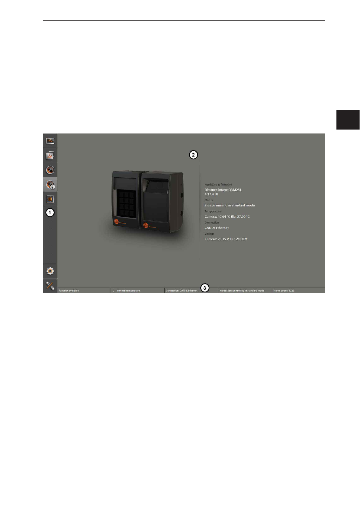
8 Device Information
The device information gives the current information about the device and the applied networks.
► Click
.
> An image of the device and the device information is shown.
UK
Field Description
Hardware & firmware Applied hardware, installed firmware version and the application
Status Device status
Temperature Temperature of the device and the illumination unit
Connection The type of connection between the ifm Vision Assistant and the device
Voltage Terminal voltage of the device and the illumination unit
57
Page 58

ifm Vision Assistant O3M
9 Calibration settings
In the calibration settings, the device can be calibrated for the intended application.
► Click
> The calibration settings are shown.
.
1: 3D view from above (not adjustable)
2: 3D view (freely adjustable)
9.1 What is calibration?
The device provides 3D coordinates for each pixel. The 3D coordinates always relate to the coordinate
origin of the world coordinate system. The calibration settings make it possible to freely define the world
coordinate system and to adjust the device to it.
The help options in the calibration settings are adapted to mobile machines. Regardless of this, the
calibration settings can be used for any application.
The three coordinate axes are X, Y and Z. The reference point of the 3D coordinate system can be
defined at will. Examples:
● measured object distance related to the device
● front part of a vehicle
● any reference point of a machine
The calibration settings provide the tools that are necessary for this.
58
Page 59

ifm Vision Assistant O3M
1
2 m
2
3
X = 2 m
2.5 m
1
2 m
2
3
X = 2 m
5 m
In the figure below, the significance of the world coordinate system is outlined as an example. The
provided 3D coordinates are always provided in the calibrated world coordinate system. This makes
it possible that the processing of the coordinate positions can take place regardless of the installation
position and angle of the device.
UK
The image above shows two different mounting positions of the device on a mobile machine. In both
cases, the world coordinate system is defined identically (1). For both mounting positions, the internal
measured value of the device differs by the mounting position (2).
By correctly calibrating the device to the world coordinate system, the same X value is provided for the
object and both mounting positions (within the world coordinate system).
59
Page 60

ifm Vision Assistant O3M
2
1
9.2 World coordinate system
The 3D data measured by the device is provided in the world coordinate system. To ensure that the world
coordinate system can be adapted to the application, the transformation between the device coordinate
system and the world coordinate system must be communicated to the system.
The device offers manual setting of the world coordinate system and automatic fine adjustment of the
world coordinate system.
The world coordinate system is defined as a right-handed, right-angled coordinate system. In the
ifm Vision Assistant, the pixels are always drawn in the currently set world coordinate system.
The world coordinate system is represented with its three axes (1). The coordinate origin is represented
by a cross (2). The rectangular pattern on the X/Y level represents the ground level (grid 1 m). The Z axis
looks up from the ground level. The X axis looks in the machine's direction of travel.
In the illustration, the device's visible range is dark green. The visible range of the illumination unit is
light green in the illustration. The areas are an aid to determine if the overlapping area of device and
illumination unit sufficiently covers the working area
9.3 Reference point of the device
The reference point of the device is defined in order to determine the correct position of the device in the
world coordinate system.
The reference point of the device is determined via the lateral reference socket (1). The reference socket
cuts the coordinate origin in the middle of the sensor (2).
60
Page 61

ifm Vision Assistant O3M
9.4 Position of the device
The following describes how the position of the device is indicated in the ifm Vision Assistant.
The following explanations refer to a reference surface to which the device is oriented. For
vehicles, the reference surface is, in most cases, the road surface. A wall or a virtual plane can be
selected as reference surface.
UK
The sensor orientation determines the installation of the device:
● vertical to the surface (portrait format)
● horizontal to the surface (landscape format)
The pictograms in the figure indicate the position of the device (view from the front).
Please consider the position of sensor screen when orienting the sensor. In the figure above, the
sensor screen is marked with a dot.
If none of the pictograms corresponds with the mounted device, please chose the pictogram that
looks most similar. The precise adjustment can be carried out later.
In this section, the reference surface is parallel to the X/Y level. The position of the reference point is
described in chapter 9.3.
With the fields "X position of sensor" and "Y position of sensor", the device can be relocated in the world
coordinate system. Due to this, the coordinate origin can be relocated to a point that is most adequate for
the application. Since the 3D coordinates of the device are provided in this world coordinate system, in
most cases, no further calculation is necessary.
In the field "Z position (height) of the sensor", the position of the device is indicated on the Z axis. The Z
axis is vertical to the reference surface. The Z position indicates the mounting height of the device.
61
Page 62

ifm Vision Assistant O3M
Z
X
Example
The following figure illustrates how to apply the world coordinate system to an application.
The reference point, the origin of the world coordinate system, is set in the front axle of the vehicle (grey
cross). The distance of the device to the reference point on the X axis is entered in the field "X position of
sensor". The distance of the device to the reference point on the Y axis is entered in the field "Y position
of sensor". The distance of the device to the reference point on the Z axis is entered in the field "Z
position of sensor".
Finally, the 3D data is calculated taking into account the entered position of the device.
The signs for the X/Y/Z axes depend on the corresponding coordinate direction in the world
coordinate system. In the figure above, the device on the X axis has a negative sign (against
driving direction) and on the Z axis a positive sign.
62
Page 63

ifm Vision Assistant O3M
1
9.5 Reference point of the illumination unit
The reference point of the illumination unit is defined in order to determine the correct position of the
illumination unit in the world coordinate system.
UK
The reference point of the illumination unit is in the centre of the illumination screen (1).
9.6 Position of the illumination unit
The following describes how the position of the illumination unit is indicated in the ifm Vision Assistant.
The illumination unit is an essential element of an O3M system. The two-housing design of the system
has been developed to meet the requirement that in certain cases is helpful to separate the illumination
and the sensor (e.g. in fog or dust).
In order to calculate the emitted signals correctly into 3D coordinates, the position of the illumination unit
must be adjusted in relation to the device.
The illumination unit shines in the direction of the measuring range. The visible range of the illumination
unit is indicated light green in the ifm Vision Assistant. Usually, the device and the illumination unit are
mounted next to each other.
The pictograms in the figure indicate the position of the illumination unit (view from the front):
● (1): illumination unit mounted to the left of the device
● (2): illumination unit mounted to the right of the device
● (3): illumination unit mounted separately from the device
If the illumination unit is mounted separately from the device (3), the position of the illumination unit must
be specified. The switch (4) determines how the position of the illumination unit is specified:
63
Page 64

ifm Vision Assistant O3M
Y
Absolute in the world coordinates: The position of the illumination
unit (1) is specified with the absolute coordinates of the world
coordinate system.
X
1
Z
Relative to the sensor: the position of the illumination unit (1)
is specified in relation to the device (2) in the world coordinate
system.
Y
X
12
Z
9.7 Mounting angle of the device
The device is capable of compensating mounting angles and to convert the 3D data into the desired
orientation.
For example, it is possible to transform the pixels of the road level irrespectively of the pitch angle of the
device, so that the pixels are parallel to the X axis. For the transformation, the device needs information
about its orientation in relation to the world coordinate system.
Al in all, three angles can be set. The angles are indicated as follows:
● (1): angle of pitch
● (2): angle of rotation
● (3): angle of roll
2
1
3
2
1
3
The figure shows the angles in relation to the orientation of the sensor.
Please note which sensor orientation is set when entering the angles
(→ „9.4 Position of the device“).
The angles can be set in two ways:
● normal mode
2
1
3
● expert mode
64
Page 65

ifm Vision Assistant O3M
9.7.1 Normal mode
In the normal mode, the angle of pitch and the angle of rotation can be set. The angle of roll is not
specified.
It is best to mount the device with an angle of roll of 0 degrees.
The angle of pitch is set in degrees in the field "Pitch angle of sensor and illumination".
The angle of rotation is set via the four buttons (1). The arrows on the four buttons indicate the driving
direction of the vehicle. The camera that is shown above the arrows shows the device's direction of view.
In the input box (2), the angle of rotation can be set precisely.
UK
The angle of roll is determined and corrected automatically if the automatic calibration function is
later used (→ „9.8 Automatic calibration“).
9.7.2 Expert mode
The switch (1) is used to activate the expert mode. In the expert mode, the rotation of the device is
entered separately for the X, Y and Z axis in the world coordinate system.
The image shows three input boxes for the rotation of the device. Depending on the orientation of the
sensor, the input boxes already contain values (→ „9.4 Position of the device“). With the values, the
overall rotation is calculated.
65
Page 66

ifm Vision Assistant O3M
Y
XYZ
The overall rotation is calculated by multiplying the rotation matrices. The
rotations around the X, Y and Z axis are described by the rotation matrices
X
R_y
R_x
R_z
The figure on the right shows the coordinate system of the device
originating from the reference point. The definition of the coordinate
axes is necessary for the configuration of the expert mode.
R_x, R_y and R_z. The rotation matrices R_x, R_y and R_z are formed
internally from the Euler angles that are entered in the input boxes.
The indices x, y and z describe the axis of rotation in the coordinate
system of the device. The overall rotation R of the device coordinate
system into the world coordinate system is defined as matrix multiplication:
Z
R = R_x * R_y * R_z
9.8 Automatic calibration
The device can be calibrated automatically in the world coordinate system. Especially setting the
orientation angle of the device is simplified by the automatic calibration.
For the automatic calibration, the following conditions must be met:
1. The origin of the world coordinate system must be placed on a plane.
2. Plane must be adjusted so that it covers a large part of the visible 3D image panel.
The automatic calibration is also possible if the origin of the world coordinate system is not on the
plane. Then, the height of the device is set to the reference level and, after the automatic calibration,
again referred to the actual world coordinate system.
3. If the automatic calibration is carried out for the first time, the position and the rotation of the device
must be set and stored manually.
Necessary accuracy for the manual setting of the position and the rotation:
● Height estimation above the plane: approx. +-0.5 m
● Angle of pitch: approx. +-10%
If the conditions are met, the automatic calibration can be released with the illustrated button.
66
Page 67

ifm Vision Assistant O3M
After the automatic calibration is released, the following note appears.
Please read the note and confirm by clicking "Ok".
If the automatic calibration is released, the following status information and settings are displayed.
UK
After the automatic calibration is started, the status information is displayed under (1).
The setting bar (2) restricts the area along the X and Y axis.
The button "Start calibration" (3) starts the automatic calibration.
After the start, a blue transparent cube is shown in the 3D view. The cube shows the search zone for the
reference level in three dimensions.
67
Page 68

ifm Vision Assistant O3M
The markings (1) show objects in the search zone that interfere with the automatic calibration.
► Reduce the search zone with the setting bar (2).
In the following figure, the search zone has been limited. The interfering objects are not considered.
The automatic calibration can now be restarted.
During the automatic calibration, the parameters are written to the device. This can take up to 15
seconds. The progress of the automatic calibration is shown next to the button.
The 3D view shows how well the automatic calibration works.
68
Page 69

ifm Vision Assistant O3M
● The colours yellow and orange signalise that the automatic calibration is not yet satisfactory.
● The colour green signalises that the automatic calibration will be successful.
The colours change during the automatic calibration.
After the automatic calibration is finished, the 3D values of the plane are placed on the plane grid:
UK
9.8.1 Equipment failure causes
The following causes can prevent the automatic calibration.
Cause Description
The initial values for height,
inclination and orientation of the
device are not accurate enough
The search zone is too small Remove interfering objects during the automatic calibration. Set a larger search zone.
There is no sufficiently large plane in
the device's field of view
There are not enough valid pixels in
the search zone
The level pixels cannot be detected in the blue search zone. Correct the following values:
● sensor orientation
● Z position of the sensor
● angle of pitch
Rotate the device to carry out the plane calibration.
Important: The rotation must not affect the angle of pitch or the angle of roll.
Alternatively, put a plane object into the field of view.
The device is mounted in a very high position. In this case, highly reflective material on the
ground can help.
69
Page 70

ifm Vision Assistant O3M
10 Image settings
In the image settings, the image of the device can be changed with different filters and parameters.
The image settings are divided into three areas:
1: Live image display (→ „10.1 Live image display“)
2: Image settings
3: Functions
70
Page 71

ifm Vision Assistant O3M
10.1 Live image display
The live image display shows the live image of the device in 2D or 3D. In the default 2D view, the live
image in the three views is displayed simultaneously:
● Distance: The pixels are shown in colour depending on the distance value.
● Amplitude: The pixels are shown in shades of grey depending on the amplitude value.
● Confidence: The pixels are displayed in accordance with the legend of the pixel properties.
UK
In the view options, it is possible to change between a 2D and 3D view. The "view options" are
described in chapter (→ „6.1 View Options“).
71
Page 72

ifm Vision Assistant O3M
10.1.1 Pixel properties
In the 2D view, the properties of a selected pixel can be displayed.
In the figure above, the pixel in column 0 and row 0 is selected.
The pixel properties contain the following values of a pixel:
Field Pixel property
Column | Row Column and row number
x x coordinates Measured value, average value and deviation [m]
y y coordinates: Measured value, average value and deviation [m]
z z coordinates: Measured value, average value and deviation [m]
Amp Amplitude
Distance Distance
In the pixel properties, the legend of the pixel status indication is also explained.
In the pixel status indication, a pixel can have one of the following statuses:
Pixel
status
Description
Pixel valid
Pixel invalid, e.g. signal too strong or too weak
Pixel is within the range of spatially filtered data (→ „10.11 Measuring range“)
Pixel estimated as ground pixel
Pixel interference detected, e.g. caused by adjacent devices (→ „10.8 Modulation frequency
mode“)
Spray/fog/dust detected (→ „10.5 Detection of spray/fog/dust“)
Pixel filtered by distance. The pixel is outside the set distance. The distance is set in the view
options (→ „6.1 View Options“)
The legend of the pixel status indication is only valid for the pixel status indication.
72
Page 73

ifm Vision Assistant O3M
10.2 Applying filters
The setting of the filters depends on the application and the environment. The filters must be set
separately for each application. When setting the filters, several aspects must be considered.
When looking at the filtered data, there is scope for interpretation, for example, due to noisy pixels.
The combination of different filters increases the reliability. However, a slight degree of uncertainty
always remains.
10.2.1 Example of area monitoring
For a better understanding of the connections between filter and application, the application "area
monitoring" and possible uncertainties are explained as an example.
The application "area monitoring" is supposed to trigger an alarm if a person enters a specific area.
The filters "signal quality filter" and "noise reduction filter" are set to [low] / [weak]. For these settings,
there are not many uncertainties caused by noisy pixels.
The filter "soiling detection" is set to [high sensitivity]. With this setting, there are not many uncertainties
caused by fog, water or ice.
Possible uncertainties due to wrongly interpreted pixels are tolerable since the security staff can inspect
the situation.
10.3 Signal quality filter
The "Signal quality filter" can filter pixels of dark objects. This reduces the number of incorrect
measurements. It does not matter how far the pixels are away. Typical applications are:
● Filtering image zones with dark objects
● Filtering invalid pixels caused by fog
● Filtering invalid pixels caused by very close objects (< 0.5 m)
Dark objects are objects that reflect little light in the infrared range (850 nm).
To the human eye, dark objects are often quite visible in the infrared range. How much light an
object reflects at 850 nm can be verified in the monitoring screen with the amplitude image (→ „6
Monitoring window“).
UK
Do not use the signal quality filter to track dark objects in the infrared range.
Depending on the setting, the filter works with low, medium or high sensitivity. The higher the sensitivity,
the more pixels are filtered and marked as invalid.
Test the ideal filter setting under difficult conditions:
● strong sunlight
● wet surfaces
73
Page 74

ifm Vision Assistant O3M
The filtered pixels are invalid (pixel properties set to 0) and cannot be used for applications.
The "signal quality filter" additionally filters noisy pixels with medium and high sensitivity. Do not
use the "noise reduction filter" simultaneously since otherwise too many invalid pixels will be
filtered.
10.4 Noise reduction filter
The "Noise reduction filter" filters pixels with excessive noise. The filter estimates the noise level and the
errors that are caused by movements that are too fast.
Depending on the setting, weak, medium or strong noise is filtered. The higher the filter is set, the lower is
the decision threshold of the filter.
Test the ideal filter setting under difficult conditions:
● strong sunlight
● wet surfaces
Do not use the noise reduction filter for the following applications:
● counting a specific number of valid pixels,
● following the movement of an object's edges.
The filters "intelligent data averaging" and "noise reduction filter" can be used simultaneously with
the following settings:
● Noise reduction filter set to "weak" or "off"
● Intelligent data averaging set to "high" (→ „10.9 Intelligent data averaging“)
74
Page 75

10.5 Detection of spray/fog/dust
"Spray/fog/dust detection" can mark recognised pixels as spray/fog/dust
(→ „10.1.1 Pixel properties“).
Spray may distort the measurement results. Spray is:
● dust
● humidity / fog
● particle clouds
ifm Vision Assistant O3M
UK
The distortion of measurement results caused by spray can be reduced by increasing the lateral distance
between the device and the illumination unit.
Test the ideal filter setting under difficult conditions:
● strong sunlight
● wet surfaces
When detecting reflectors, the distance between the device and the illumination must be as short
as possible. Otherwise, the reflectors will not be properly recognised.
In narrow and closed locations, spray/fog/dust can only be recognised with restrictions.
The pixels recognised as spray, fog or dust are invalid (pixel properties set to 0) and cannot be
used for applications.
If more than 30% of the pixels are recognised as spray, fog or dust, the "availability" bit is set to
0 (not available). The status of the bit can be retrieved via the CAN and Ethernet interface. In the
interface descriptions, the CAN and Ethernet interfaces are described in detail.
75
Page 76

ifm Vision Assistant O3M
10.6 Soiling detection
The "Soiling detection" recognises soiling of the device's front screen. A soiled front screen leads to
incorrect measuring results. A dedicated LED regularly checks the permeability of the front screen and
detects soiling.
Typical types of soiling are:
● Ice
● Dust
● Humidity/fog/water
● Oil/grease
Soiling of the front screen of the illumination unit is not recognised.
The current degree of soiling is indicated as a percentage value in the status bar in the bottom left corner.
In the status bar, "Function available" is displayed if no soiling is detected:
The degree of soiling (warning value) is provided as a percentage value via CAN and can be evaluated in
applications.
Test the ideal filter setting under difficult conditions:
● strong sunlight
● wet surfaces
10.6.1 Setting the sensitivity
Depending on the setting, the filter works with low, medium or high sensitivity.
The following table shows the sensitivity with which soiling is recognised most reliably.
Dirt Low sensitivity Medium sensitivity High sensitivity
Ice recognised recognised recognised
Dead leaves recognised recognised recognised
Dust partially recognised recognised recognised
Humidity/fog/water not recognised partially recognised recognised
Dirt not recognised not recognised recognised
The setting "high sensitivity" detects smallest degrees of soiling and may lead to false alerts.
Highly reflective objects close to the device (< 0.5 m) are detected as soiling.
76
Page 77

ifm Vision Assistant O3M
10.6.2 Removal of soiling
Depending on the soiling, use one of the following methods of removal:
Dirt Method of removal
Ice ► scratch the ice off carefully or
► wait until the device is warmed up and the ice has melted
(depends on the ambient temperature)
Dust ► remove with a damp micro-fibre cloth
Humidity/fog/water ► remove with a micro-fibre cloth
Oil/grease ► remove using a cleaning agent
Due to the hysteresis, it takes a few seconds after the soiling is removed before "Function
available" appears in the status bar.
10.7 Frame rate
The "frame rate" of the device, i.e. the frequency with which the images are captured, can be set.
UK
The frame rate is set as Hertz [Hz] frequency. The default value is 50 Hz.
A low frame rate has several advantages:
● low bus load
● low electric power (important factor for battery-operated systems)
● reduced heating of the illumination unit
Choose the highest possible frame rate when using the device on mobile machines.
77
Page 78

ifm Vision Assistant O3M
10.8 Modulation frequency mode
The "Modulation frequency mode" enables the use of several devices in the same field of view.
Each device uses several modulation frequencies to increase the range. If more than one device is
needed for an application, interferences may occur. The devices interfere with each other by using the
same modulation frequency.
With the "Modulation frequency mode", you can assign different modulation frequencies to the devices.
The modulation frequency is set in the "Modulation frequency mode":
You can choose among the following:
● three frequency sets with fixed default modulation frequencies
● one frequency set with a random choice of modulation frequencies
Test the ideal filter setting under difficult conditions:
● strong sunlight
● wet surfaces
10.8.1 Fixed modulation frequencies
The fixed frequency sets consist of three modulation frequencies which cannot be changed.
1 2 3
f
f
f
f
f
f
f
f
f
The fixed frequency sets are suited for applications with the following properties:
● fixed device position (no vehicles)
● maximum of three devices in one field of view
The noise level of the fixed modulation frequencies is lower than the one of the random modulation
frequencies (→ „10.8.2 Random modulation frequencies“).
► Use the fixed modulation frequencies by preference.
78
Page 79

ifm Vision Assistant O3M
10.8.2 Random modulation frequencies
The random modulation frequencies apply a method that changes the frequency with each image
(arbitrary frequency hopping). The frequencies are selected randomly.
f1
f2
f12
f13
UK
The frequency set with random selection of modulation frequencies is suited for applications with the
following properties:
● mobile use of the devices (AGV, drone, vehicles, etc.)
● more than three devices in the field of view
When using the random modulation frequencies, interferences are possible. The interferences are
recognised and the affected pixels are marked as invalid.
► Use the fixed modulation frequencies by preference.
79
Page 80

ifm Vision Assistant O3M
10.9 Intelligent data averaging
The "intelligent data averaging" accesses raw data of the device and calculates an average value of the
raw data. Typical applications are:
● Signal noise reduction (→ „10.9.2 Example of a signal noise reduction“)
● Increase the number of valid pixels (→ „10.9.3 Example for increasing the number of valid pixels“)
● Compensation of bright sunlight
● Improve the recognition of distant objects
● Improve the recognition of objects with low reflectivity
The set value indicates the number of raw data (frames) that are to be used for the calculation of the
average value.
The intelligent data averaging may only be used with fixed modulation frequencies
(→ „10.8.1 Fixed modulation frequencies“).
The calculation of the average value causes a motion blur effect.
► Select the "low" setting if the application has objects with high dynamics.
Test the ideal filter setting under difficult conditions:
● strong sunlight
● wet surfaces
The intelligent data averaging can reduce the sensitivity of the noise reduction filter (→ „10.4 Noise
reduction filter“).
80
Page 81

ifm Vision Assistant O3M
10.9.1 Operating principle
The device can calculate average values in two different ways:
● Basic functions (→ „11 2D overlay“)
● Intelligent data averaging
For the calculation of average values via the basic functions, only the valid pixels in an ROI are used.
For the calculation of average values via the intelligent data averaging, the raw data is used. The raw
data contains valid and invalid pixels. The intelligent data averaging can make invalid pixels valid again.
10.9.2 Example of a signal noise reduction
In the following, you will find an example of how the intelligent data averaging reduces the signal noise.
Example Description
The device is oriented towards a car park
with cars.
The distances between the device and
cars are indicated by means of the
colours (→ „6 Monitoring window“):
● 1st row of cars in red
● 2nd row of cars in yellow
● 3rd row of cars in blue
Monitoring screen
Calculation of the average value with low
sensitivity:
UK
Monitoring screen
Calculation of the average value with high
sensitivity:
Result:
The signal noise is significantly reduced.
81
Page 82

ifm Vision Assistant O3M
10.9.3 Example for increasing the number of valid pixels
In the following, you find an example of how the intelligent data averaging increases the number of valid
pixels.
Example Description
The device is oriented towards a car park
with cars.
The distances between the device and
cars are indicated by means of the
colours (→ „6 Monitoring window“):
● 1st row of cars in red
● 2nd row of cars in yellow
● 3rd row of cars in blue
Monitoring screen
The calculation of the average value is
switched off:
Monitoring screen
Calculation of the average value with low
sensitivity:
Result:
The number of valid pixels has increased.
82
Page 83

ifm Vision Assistant O3M
10.10 Reflector threshold value
The filter "Reflector threshold value" can filter pixels of bright objects. It does not matter how far the pixels
are away. Typical applications are:
● Filtering image zones with bright objects
The filter "Reflector threshold value" only works with the firmware
"OD - Object Detection and Collision Avoidance" (→ „7.1.3 Firmware update“).
Bright objects are objects that reflect much light in the infrared range. The objects are brighter than
white in the infrared range, e.g. a reflector (cat's eye, reflective tape, etc.).
How much light an object reflects can be verified in the monitoring screen with the amplitude image
(→ „6 Monitoring window“).
Do not use the reflector threshold value filter to track bright objects in the infrared range.
UK
Depending on the setting, the filter works with a low, medium or very high threshold level. The lower the
threshold level, the more pixels are recognised and filtered as a reflector. With a low threshold level, the
probability that a pixel is mistaken for a reflector increases.
When detecting reflectors, the distance between the device and the illumination must be as short
as possible. Otherwise, the reflectors will not be properly recognised.
Test the ideal filter setting under difficult conditions:
● strong sunlight
● wet surfaces
83
Page 84

ifm Vision Assistant O3M
10.11 Measuring range
The measuring range ① isolates the data which is to be used for further calculations. If the measuring
range ① is set, only the data within the min/max values are used for further calculation. The data outside
the min/max values is abandoned and is available for further functions.
Setting the measuring range
► Enter min/max values for the coordinate axes.
①
②
②
z
x
y
The measuring range can be displayed and hidden in the monitoring window
(→ „6 Monitoring window“).
84
Page 85

ifm Vision Assistant O3M
10.11.1 Exclusion area
In addition to the measuring range, up to two exclusion areas ② can be set within the measuring
range ①. The data within the min/max values are excluded from further calculations. This ignores, for
example, attachments in the visible range.
Setting exclusion areas
► Enter min/max values for the coordinate axes.
①
②
UK
The exclusion areas ② are displayed in the monitoring window:
②
z
x
y
Set the exclusion area a bit larger than the objects to be excluded. Thereby, measuring errors on
object edges caused by mixed pixels are excluded by further calculations.
If the 3D pixel data is transmitted via Ethernet, the spatial filtering is marked in the confidence
interval. The originally measured 3D pixel data is additionally available.
85
Page 86

ifm Vision Assistant O3M
11 2D overlay
The 2D overlay is a function which is available for each firmware.
Some functions of the 2D overlay require a specific type of firmware
(→ „7.1.3 Firmware update“).
The 2D overlay is only available for the O3M2xx devices.
The 2D camera of the O3M2xx displays a 2D image of the application. With the 2D overlay, the output
of the 2D image can be set. Additionally, the following elements can be shown as an overlay in the 2D
image:
● Graphics (logos, warning symbols, etc.)
● Text (system status, distance information, etc.)
● Vectors (ellipses, polygons, polylines)
Each element has its own ID. The visibility of the elements can be adjusted in many ways.
The 2D overlay is divided into three areas:
1: Preview of the 2D overlay
2: Settings: Functions
86
Page 87

11.1 Overlay options
With the "overlay options", the way the 2D image is displayed can be set.
The "2D output on" switch activates the output of the 2D image.
If the switch is in the off position, no image is provided via the
analogue video interface of the device.
The "Overlay on" switch activates the overlay. If the switch is in the
off position, only the 2D output is displayed (provided that the 2D
output is activated).
ifm Vision Assistant O3M
The switch "Visualise 3D field of view" activates the visualisation of
a frame in the 2D overlay which indicates the 3D measuring range.
The angle of aperture of the 3D measuring range is smaller on the
vertical axis.
Due to perspective distortions, the display of the 3D
measuring range is merely an indicator.
11.2 Pallet
The "pallet" is used to add texts, vectors (ellipses, polygons, polylines) and images to the 2D overlay.
The pallet contains 4 buttons:
The [Add text] button adds a configurable text to the 2D overlay
(→ „11.2.1 Add text“).
The [Add ellipse] button adds a configurable ellipse to the 2D overlay
(→ „11.2.2 Adding a vector“).
The [Add polygon] button adds a configurable polygon to the 2D overlay
(→ „11.2.2 Adding a vector“).
The [Add polyline] button adds a configurable polyline to the 2D overlay (→ „11.2.2 Adding a
vector“).
UK
87
Page 88

ifm Vision Assistant O3M
11.2.1 Add text
The [Add text] button changes the mouse pointer into a cross hair. After that, a text can be
added to the "Preview of the 2D overlay" by clicking.
By clicking on , the text can be edited and the following window
opens.
The text has the ID 107. Each text has its own ID.
In the "text" field, the text to be displayed can be edited.
In the "text" field, the variables can be used in the form of text
replacement codes (→ „16.2 Text replacements and conditional
codes“).
The text replacement codes start with a "%". By entering the "%" in
the text field, a selection list opens that features the available text
replacement codes. Several text replacement codes additionally
require entering an ID (e.g. the ROI group number).
The functions of the selected text replacement code are shown by
clicking.
The available text replacement codes depend on the installed
firmware.
Only one text replacement code can be used per text field.
4 fonts are available for the text design. The fonts differ in shape and
size.
With the "Colour" field, the text colour can be changed.
With the "Background colour" field, the background colour of the text
can be changed.
88
Page 89

ifm Vision Assistant O3M
In the list "Visible", the visibility of the text can be set.
The visibility of the text can be
coupled to the conditions of the
device.
The available conditions depend on the installed firmware (→ „7.1.3 Firmware update“).
The following conditions are available in each firmware:
● Static
● Operation Mode
UK
● Availability
● Digital I/O
Clicking on
deletes the text.
11.2.2 Adding a vector
The following buttons add a vector to the "Preview of the 2D overlay":
[Add ellipse]: After clicking on the button, the mouse pointer changes into a cross hair. After
clicking on the button, the mouse pointer changes into a cross hair.
[Add polygon]: After clicking on the button, the mouse pointer changes into a cross hair.
Then, the polygon can be drawn in the "Preview of the 2D overlay" by holding the mouse
button.
Drawing the polygon can be quit by double-clicking the mouse button.
[Add polyline]: After clicking on the button, the mouse pointer changes into a cross hair. Then,
the polyline can be drawn in the "Preview of the 2D overlay" by holding the mouse button.
Drawing the polyline can be quit by double-clicking the mouse button.
89
Page 90

ifm Vision Assistant O3M
11.2.3 Adding a graphic.
The following buttons add a graphic to the "Preview of the 2D overlay".
The [Add] button opens the file selection which is used to add
further graphics to the selection shown below.
The selection shows all graphics stored on the device.
The graphics "Icons #2", "Icons #3" and "Icons #4" are already
stored on the device when delivered. Each added graphic is shown
below the icon. Each graphic includes its own ID (e.g.: "#65532").
The following graphic formats are supported:
png, jpg, bmp, ico and gif.
Graphics with transparency are only possible in png format.
By clicking on
With the symbol
from the device.
After clicking on the graphic in the selection, the mouse pointer
turns into a cross hair. Then, the graphic in the 2D overlay is shown
in the "Preview of the 2D overlay".
The graphics can be edited in the "Preview of the 2D overlay":
● move the graphic by holding the mouse button,
● scale the graphic by clicking on the corner dots.
The graphic is always scaled at a fixed aspect ratio. The
graphic can only be scaled up to its original size.
, the graphic can be edited and the following window opens.
The graphic has the ID 6. Each graphic has an own ID.
The graphics are directly saved on the device. Thereby, the
graphics can be controlled via CAN. To control them, the IDs
are required.
In the list "visible", the visibility of the graphic can be set.
, the graphic is deleted from the selection and
90
The visibility of the graphic can be
coupled to the different conditions
of the device.
Page 91

ifm Vision Assistant O3M
The available conditions depend on the installed firmware (→ „7.1.3 Firmware update“).
The following conditions are available in each firmware:
● Static
● Operation Mode
● Availability
● Digital I/O
By clicking on
With the symbol , the graphic is deleted from the selection and from the device.
,the graphics is deleted from the selection, but it stays in the device.
11.2.4 Live ticker
The live ticker shows at a glance whether the video image is active.
If the video image is active, the live ticker is
turning in the top right corner in the "Preview
of the 2D overlay" (1).
UK
By clicking on
The live ticker can be edited in the "Preview of
the 2D overlay":
● Move the live ticker by holding the mouse
button.
, the live ticker can be edited and the following window opens.
The ID of the live ticker is 7.
In the list "Visible", the visibility of the live
ticker can be set.
The visibility of the text can be
coupled to the different conditions
of the device.
91
Page 92

ifm Vision Assistant O3M
The available conditions depend on the installed firmware (→ „7.1.3 Firmware update“).
The following conditions are available in each firmware:
● Static
● Operation Mode
● Availability
● Digital I/O
Clicking on
To restore the live ticker, click on an icon of the live ticker in the selection. The mouse pointer turns
into a cross hair. Then, the live ticker in the 2D overlay is shown in the "Preview of the 2D overlay".
deletes the live ticker. The live ticker can be restored.
11.3 Variant options of the OD firmware
The variant options contain options to display 3D objects in the 2D overlay.
The available options depend on the installed firmware (→ „7.1.3 Firmware update“). The following
options require the OD firmware object detection.
In the field "Max. drawn objects", the maximum number of normal
objects and reflector objects which are simultaneously indicated with
the 2D overlay can be entered. If more objects are recognised as are
specified in the "Max drawn objects" field, the objects at the shortest
distance will be indicated with priority. If "Display reflector objects" is
activated, reflector objects are shown with priority.
The switch "Display normal objects" activates the visualisation of
normal objects in the 2D overlay.
The switch "Display reflector objects" activates the visualisation of
reflector objects in the 2D overlay.
For the visualisation of reflector objects in the 2D overlay, the 3D
reflector recognition must be active. The 3D reflector recognition
can be activated in the object recognition application.
92
Page 93

ifm Vision Assistant O3M
11.4 Variant options of the DI firmware
The variant options contain options to display 3D objects in the 2D overlay.
The available options depend on the installed firmware (→ „7.1.3 Firmware update“). The following
options require the DI firmware basic functions.
With the variant options of the DI firmware, Regions of Interest (ROI)
are shown and configured in the 2D overlay.
The switch "Visualise ROIs" activates the visualisation of ROIs in the
2D overlay.
In the list "ROI visualization design", the way the ROIs are visualised
can be set. The following types of visualisation are available:
● [3D moving wall]
(→ „11.4.1 Visualising 3D ROIs as a moving wall“)
● [3D projection floor projection]
(→ „Colour mode [Colour map]“)
● [2D ROI]
(→ „11.4.3 Visualisation of 2D ROIs“)
11.4.1 Visualising 3D ROIs as a moving wall
The ROI visualisation type "3D moving wall" shows the provision of the
ROI groups in the x, y and z axis (length, width and hight) as a coloured
overlay. The coloured overlay is visualised as a wall.
"Output" refers to the measuring result of the ROI group
(→ „12.2 Global settings“).
The ROI visualisation type "3D moving wall" is only suitable for
three-dimensionally defined ROIs (→ „12.1 ROI mode“).
UK
In the figure on the left, the output of 4 ROI groups is visualised as a
coloured overlay and the X values as a text.
[Colour map] is set as "colour mode".
The "3D ROI frame" is set to [black].
The output of the ROI group can additionally be shown as text. In "text
visualisation ROI results", the control fields can be activated:
● X value
● Y value
● Z value
The text fields can overlap if several ROI groups are provided at
the same time.
93
Page 94

ifm Vision Assistant O3M
Colour mode [Colour map]
In the list "colour mode", the behaviour of the colours of the colour
overlay can be set. The following colour modes are available:
● [Colour map]
The colour changes with the set reference value.
● [Colour switch]
After a threshold value is reached, there is a change between 2
colours.
● [Logic output]
The colour changes according to the condition of the virtual digital
outputs of the ROI groups.
● [Defined colour]
The colour setting is fixed and does not change.
In the colour mode [Colour map], the colour changes with the set
reference value.
The "reference value" defines with which ROI group output the moving
wall shifts. The following reference values can be selected:
● [X] - The moving wall is projected in the Y-Z level and moves with
the reference value X.
● [Y] - The moving wall is projected in the X-Z level and moves with
the reference value Y.
● [Z] - The moving wall is projected in the Y-X level and moves with
the reference value Z.
The reference value additionally defines which ROI group output is
used as basis for the colouring of the moving wall.
The "Map type" defines the type of the colour gradient. You can
choose among the following:
● Colour map 1
● Colour map 1 mirrored
● Colour map 2
● Colour map 2 mirrored
A start and end value can be set:
● Output of the ROI group < start value: The colour of the start value
is used.
94
● Output of the ROI group > end value: The colour of the end values
is applied.
The "preview" graphically shows the set colour map in combination
with the start and end value.
The "3D ROI frame" is configurable:
● By activating the control field, the "3D ROI frame" is shown.
● By clicking on the colour field, the colour of the "3D ROI frame" can
be changed.
Page 95

Colour mode [Colour switch]
ifm Vision Assistant O3M
In the colour mode [Colour switch], there is a change between 2
colours when a threshold is reached.
In the figure on the left, the output of 4 ROI groups and the X and Y
values are visualised as a colour change.
[Colour switch] is set as colour mode.
The "3D ROI frame" is deactivated.
The "reference value" defines the output of the ROI group which the
threshold value takes as a reference. The following reference values
can be selected:
● [X] - The moving wall is projected in the Y-Z level and moves with
the reference value X.
● [Y] - The moving wall is projected in the X-Z level and moves with
the reference value Y.
● [Z] - The moving wall is projected in the Y-X level and moves with
the reference value Z.
The "colour switch threshold" defines the threshold for the colour
change. The threshold value is based on the set reference value.
The "colour direction" determines what is to happen when the
threshold is exceeded or not reached. Change from
● [read to green]
● [green to read]
UK
The "3D ROI frame" is configurable:
● By activating the control field, the "3D ROI frame" is shown.
● By clicking on the colour field, the colour of the "3D ROI frame" can
be changed.
95
Page 96

ifm Vision Assistant O3M
Colour mode [Logic output]
In the colour mode [Logic output] the colour changes in relation to the
condition of the virtual digital outputs of the ROI groups.
When using the standard logic of the device, the virtual output
with the number of the ROI group is used.
► Ensure that the numbering of the virtual outputs is correct if a
logic is used that you have defined yourself.
In the figure on the left, the output of 4 ROI groups and the X and Y
values are visualised as a logic output.
[Logic output] is set to "colour mode".
The "3D ROI frame" is set to [black].
The "reference value" defines with which ROI group output the moving
wall shifts. The following reference values can be selected:
● [X] - The moving wall is projected in the Y-Z level and moves with
the reference value X.
● [Y] - The moving wall is projected in the X-Z level and moves with
the reference value Y.
● [Z] - The moving wall is projected in the Y-X level and moves with
the reference value Z.
The colour fields "Color when output=off" and "Color when output=on"
determine how the moving wall is visualised for the 2 possible
conditions.
The "3D ROI frame" is configurable:
● By activating the control field, the "3D ROI frame" is shown.
● By clicking on the colour field, the colour of the "3D ROI frame" can
be changed.
96
Page 97

Colour mode [defined colour]
ifm Vision Assistant O3M
In the colour mode [defined colour], the colour setting is fixed and
does not change.
In the figure on the left, the outputs of 4 ROI groups are shown as
defined colour.
[Defined colour] is set as "colour mode".
The "3D ROI frame" is shown in [white].
The "reference value" defines with which ROI group output the moving
wall shifts. The following reference values can be selected:
● [X] - The moving wall is projected in the Y-Z level and moves with
the reference value X.
● [Y] - The moving wall is projected in the X-Z level and moves with
the reference value Y.
● [Z] - The moving wall is projected in the Y-X level and moves with
the reference value Z.
The "fixed colour" determines the defined colour for the moving wall.
The the setting of the colour of the moving wall is fixed and does not
change.
The "3D ROI frame" is configurable:
● By activating the control field, the "3D ROI frame" is shown.
● By clicking on the colour field, the colour of the "3D ROI frame" can
be changed.
UK
97
Page 98

ifm Vision Assistant O3M
11.4.2 Visualisation of 3D ROIs as a projection on the fl oor
The ROI visualisation type "3D floor projection" shows the provision of
the ROI groups in the x, y and z axis (length and width) as a coloured
overlay. The coloured overlay is visualised as a projection on the floor.
"Output" refers to the measuring result of the ROI group
(→ „12.2 Global settings“).
The ROI visualisation type "3D floor projection" is only suitable for:
● three-dimensionally defined ROIs (→ „12.1 ROI mode“),
● ROIs lying next to each other (x and y axis)
(not suited for ROIs stacked on top of each other (z axis).
In the figure on the left, the provision of 2 ROI groups is visualised as a
coloured overlay on the floor and the X values as a text.
[Colour map] is set as "colour mode".
The "moving reference line" is set to [white].
The output of the ROI group can additionally be shown as text. In "text
visualisation ROI results", the control fields can be activated:
● X value
● Y value
● Z value
The text fields can overlap if several ROI groups are provided at
the same time.
In the list "colour mode", the behaviour of the colours of the colour
overlay can be set. The following colour modes are available:
● [Colour map]
The colour changes with the set reference value.
● [Colour switch]
After a threshold value is reached, there is a change between 2
colours.
● [Logic output]
The colour changes according to the condition of the virtual digital
outputs of the ROI groups.
● [Defined colour]
The colour setting is fixed and does not change.
98
Page 99

Colour mode [Colour map]
ifm Vision Assistant O3M
In the colour mode [Colour map], the colour changes with the set
reference value.
The "reference value" defines with which output of the ROI group the
"moving reference line" shifts. The following reference values can be
selected:
● [X] - The "moving reference line" is projected in the Y-Z level and
moves with the reference value X.
● [Y] - The projection on the floor is projected in the X-Z level and
moves with the reference value Y.
● [Z] - The projection on the floor is projected in the Y-X level and
moves with the reference value Z.
The reference value additionally defines which provision of the ROI
group is used as basis for the projection on the floor.
The "Map type" defines the type of the colour gradient. You can
choose among the following:
UK
● Colour map 1
● Colour map 1 mirrored
● Colour map 2
● Colour map 2 mirrored
A start and end value can be set:
● Output of the ROI group < start value: The colour of the start value
is used.
● Output of the ROI group > end value: The colour of the end values
is applied.
The "preview" graphically shows the set colour map in combination
with the start and end value.
The "moving reference line" shows the output of the ROI groups
graphically as a line in the projection on the floor. The "moving
reference line" can be set:
● By activating the control field, the "moving reference line" is shown.
● By clicking on the colour field, the colour of the "moving reference
line" can be changed.
99
Page 100

ifm Vision Assistant O3M
Colour mode [Colour switch]
In the colour mode [Colour switch], there is a change between 2
colours when a threshold is reached.
The "reference value" defines with which ROI group output the "moving
reference line" shifts. The following reference values can be selected:
● [X] - The "moving reference line" is projected in the Y-Z level and
moves with the reference value X.
● [Y] - The projection on the floor is projected in the X-Z level and
moves with the reference value Y.
● [Z] - The projection on the floor is projected in the Y-X level and
moves with the reference value Z.
The "colour switch threshold" defines the threshold for the colour
change. The threshold value is based on the set reference value.
The "colour direction" determines what is to happen when the
threshold is exceeded or not reached. Change from
● [read to green]
● [green to read]
The "moving reference line" shows the output of the ROI groups
graphically as a line in the projection on the floor. The "moving
reference line" can be set:
● By activating the control field, the "moving reference line" is shown.
● By clicking on the colour field, the colour of the "moving reference
line" can be changed.
100
 Loading...