

Page 1

Operating instructions
3D camera
O3D301
O3D303
O3D311
O3D313
706397 / 03 10/2015
UK
Page 2

3D camera
2
Inhalt
1. Preliminary note...................................................................4
1.1 Symbols used .................................................................4
1.2 Warnings used ................................................................4
2. Safety instructions .................................................................4
2.1 General ......................................................................4
2.2 Target group ..................................................................4
2.3 Electrical connection............................................................4
2.4 Tampering with the device .......................................................4
3. Functions and features .............................................................5
4. Items supplied ....................................................................5
5. Accessories . . . . . . . . . . . . . . . . . . . . . . . . . . . . . . . . . . . . . . . . . . . . . . . . . . . . . . . . . . . . . . . . . . . . . .5
6. Installation ......................................................................6
6.1 Select installation location .......................................................6
6.2 Additional camera installation guidance .............................................7
6.2.1 Typical warning limits for O3D301 / O3D303 .....................................7
6.2.2 Typical warning limits for O3D311 / O3D313 .....................................8
6.2.3 Reduce surface temperature .................................................8
6.3 Install camera .................................................................9
6.4 Mounting accessories ...........................................................9
7. Electrical connection ..............................................................10
7.1 Wiring .....................................................................10
7.1.1 Pin 1 / 3 (24 V / GND)......................................................11
7.1.2 Pin 2 (trigger input) ........................................................11
7.1.3 Pin 4 / 5 (ready / cascading).................................................11
7.2 Wiring examples ..............................................................12
7.2.1 Trigger image capture with proximity sensor ....................................12
7.2.2 Install several cameras next to each other .....................................13
8. Indicators .....................................................................14
9. Set-up .....................................................................15
9.1 Set parameters of the camera ...................................................15
9.2 Detect object.................................................................15
10. Maintenance, repair and disposal ...................................................16
10.1 Clean .....................................................................16
10.2 Update firmware .............................................................16
10.3 Replace camera .............................................................16
11. Approvals/standards .............................................................16
12. Scale drawings..................................................................17
12.1 O3D303 / O3D313 ...........................................................17
12.2 O3D301 / O3D311 ...........................................................17
13. Appendix .....................................................................18
13.1 Required Ports ..............................................................18
13.2 XML-RPC Interface...........................................................18
13.2.1 Sample XML-RPC command . . . . . . . . . . . . . . . . . . . . . . . . . . . . . . . . . . . . . . . . . . . . . . .18
13.2.2 XML-RPC Objects .......................................................19
13.3 Process Interface ............................................................22
13.3.1 Sending Commands ......................................................22
13.3.2 Receiving Images ........................................................22
13.3.3 Image data .............................................................23
13.3.4 Additional Information for CONFIDENCE_IMAGE ...............................26
13.3.5 Configuration of PCIC Output...............................................27
13.4 Process Interface Command Reference...........................................31
13.4.1 t Command (Asynchronous Trigger)..........................................31
13.4.2 T? Command (Synchronous Trigger) .........................................31
13.4.3 I? Command ............................................................31
Page 3

3
3D camera
UK
13.4.4 p Command ............................................................32
13.4.5 a Command ............................................................33
13.4.6 A? Command ...........................................................33
13.4.7 v Command ............................................................34
13.4.8 V? Command ...........................................................34
13.4.9 c Command ............................................................34
13.4.10 C? Command . . . . . . . . . . . . . . . . . . . . . . . . . . . . . . . . . . . . . . . . . . . . . . . . . . . . . . . . . .35
13.4.11 S? Command ..........................................................35
13.4.12 G? Command ..........................................................36
13.4.13 H? Command . . . . . . . . . . . . . . . . . . . . . . . . . . . . . . . . . . . . . . . . . . . . . . . . . . . . . . . . . .37
13.5 XML-RPC Command Reference ................................................38
13.5.1 Parameter API ..........................................................38
13.5.2 Main Object.............................................................39
13.5.3 Session Object . . . . . . . . . . . . . . . . . . . . . . . . . . . . . . . . . . . . . . . . . . . . . . . . . . . . . . . . . .42
13.5.4 Edit Mode Object ........................................................44
13.5.5 Device Config Object .....................................................45
13.5.6 Device/Network Config Object ..............................................49
13.5.7 Application Config Object ..................................................49
13.5.8 Application/Imager Config Object ............................................51
13.5.9 Image Settings and Filter Parameters ........................................56
Licences and trademarks
Microsoft®, Windows®, Windows XP®, Windows Vista®, Windows 7®, Windows 8® and Windows 8.1®
are registered trademarks of Microsoft Corporation.
Adobe® and Acrobat® are registered trademarks of Adobe Systems Inc.
All trademarks and company names are subject to the copyright of the respective companies.
This device contains (maybe modified) open source software which is subject to special licensing terms.
For copyright information and licensing terms please refer to:
www.ifm.com/int/GNU
For software subject to the GNU General Public License or the GNU Lesser General Public License the
source code can be requested against payment of the copying and shipping costs.
Page 4

3D camera
4
1. Preliminary note
This document is intended for specialists. These specialists are people who are qualified by their
appropriate training and their experience to see risks and to avoid possible hazards that may be caused
during operation or maintenance of the device. The document contains information about the correct
handling of the device.
Read this document before use to familiarise yourself with operating conditions, installation and operation.
Keep this document during the entire duration of use of the device.
1.1 Symbols used
► Instructions
> Reaction, result
[…] Designation of keys, buttons or indications
→ Cross-reference
Important note
Non-compliance may result in malfunction or interference.
Information
Supplementary note
1.2 Warnings used
NOTICE
Warning of damage to property.
2. Safety instructions
2.1 General
These instructions are an integral part of the device. They contain texts and figures concerning the correct
handling of the device and must be read before installation or use.
Observe the operating instructions. Non-observance of the instructions, operation which is not in
accordance with use as prescribed below, wrong installation or incorrect handling can seriously affect the
safety of operators and machinery.
2.2 Target group
These instructions are intended for authorised persons according to the EMC and low-voltage directives.
The device must be installed, connected and put into operation by a qualified electrician.
2.3 Electrical connection
Disconnect the device externally before handling it.
The connection pins may only be supplied with the signals indicated in the technical data and on the
device label and only the approved accessories of ifm may be connected.
2.4 Tampering with the device
In case of malfunctions or uncertainties please contact the manufacturer. Any tampering with the
device can seriously affect the safety of operators and machinery. This is not permitted and leads to the
exclusion of any liability and warranty claims.
Page 5

5
3D camera
UK
3. Functions and features
The O3D3xx 3D camera is an optical camera which measures the distance between the camera and the
nearest surface point by point using the time-of-flight principle. The camera illuminates the scene with an
infrared light source and calculates the distance by means of the light reflected from the surface.
The camera supplies data which describes the captured scene three-dimensionally. This distance data
can be output via Ethernet and evaluated by the user. Parameter setting of the camera is also done via
Ethernet.
The camera may only be used under the operating conditions specified in the data sheet.
The camera safety is rated for use under the following operating conditions:
• Indoor use
• Altitudes up to 2000 m
• Relative air humidity up to max. 90 %, non condensing
• Degree of soiling 3
4. Items supplied
The following items are supplied:
● O3D3xx 3D camera
● USB memory stick with software and documentation
● Brief instructions, ident no. 80227244
The data sheet and other documentation (software manual, etc.) are available on our website:
www.ifm.com
→ Data sheet search → e.g. O3D303 → Operating instructions
5. Accessories
The following accessories are needed for the operation of the camera:
Article number Description
E11950 Power supply cable for camera
E11898 M12 industrial Ethernet connection cable
The ifm Vision Assistant software is available free of charge on our website:
www.ifm.com
→ Service → Download → Industrial imaging
Page 6
3D camera
6
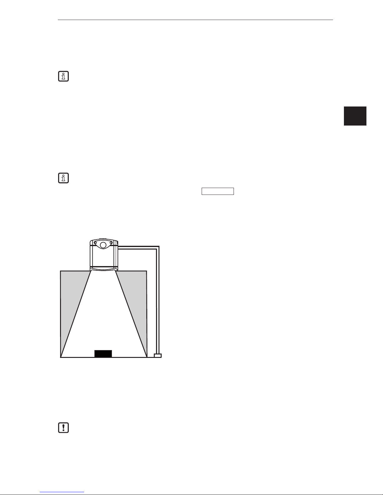
6. Installation
The chapter describes what has to be observed before installation and how to install the camera.
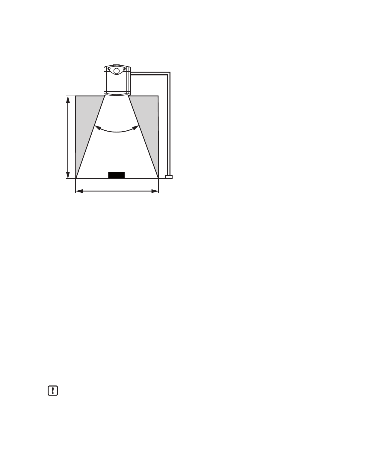
②
①
③
④
⑤
①: Camera
②: Angle of aperture
③: Object
④: Field of view
⑤: Distance between camera and object
6.1 Select installation location
Observe the following instructions for the selection of the installation location:
► The object ③ must be completely in the field of view ④.
> The size of the field of view depends on the camera type and is indicated in the data sheet. The size
of the field of view also depends on the distance of the camera to the object ⑤: With increasing
distance the field of view becomes larger.
► Take tolerances into account when positioning the object.
► When determining the distance between camera and object ⑤ take the measuring range of the camera
into account.
> The measuring range is indicated in the data sheet of the camera.
► Select a distance as small as possible between camera and object ⑤.
> If the distance is as small as possible, the object is detected with the maximum resolution.
► Avoid any strong ambient light and sunlight at the installation location.
> An extraneous light level of over 8 klx (with solar spectrum) causes measurement errors. In fact, only
the infrared component between 800 and 900 nm is of concern.
► Avoid installation in heavily polluted environments.
> In heavily polluted environments the camera lense will get dirty despite downwards orientation ①.
► Avoid transparent panes between the camera ① and the object ③.
> Transparent panes reflect part of the light even if a very clean glass pane is used.
If the instructions are not observed, measurement errors may occur.
Page 7
7
3D camera
UK
6.2 Additional camera installation guidance
The surface temperature of the camera depends on the operating mode, the parameter selection and the
thermal exposure of the camera to the environment.
Make sure that the camera complies with the following requirement:
The surface temperature for easily accessible surfaces may be max. 25 °C higher than the ambient
temperature (to IEC 61010-2-201).
The following diagrams contain typical warning limits as a reference for the installer.
The diagrams are valid for the following operating modes:
● Low [1 exposure]
● Moderate [2 exposures]
● High [3 exposures]
In the event of moderate and high exposures the typical warning limits must be determined via the
sum of the exposure times. The exposure times are indicated in the software ifm Vision Assistant.
Follow one of the instructions if the warning limits are exceeded:
► Reduce the surface temperature (→ 6.2.3).
► Mount the camera in a location or housing that provides protection from the heat source but maintains
air circulation around the camera.
> An increase in the surface temperature of the camera should be prevented.
The parameter "Max. background distance" is set in the ifm Vision Assistant. In the diagrams the
warning limits of the parameter are shown with dashed and continuous lines.
If the camera is in one of the dotted areas, the surface temperature must be reduced, (→ 6.2.3).
If the warning limit is exceeded despite a heat-dissipating installation, it is possible to additionally
mount the contact protection.
If you stay below the typical warning limits in case of normal installation, no measures need to be taken.
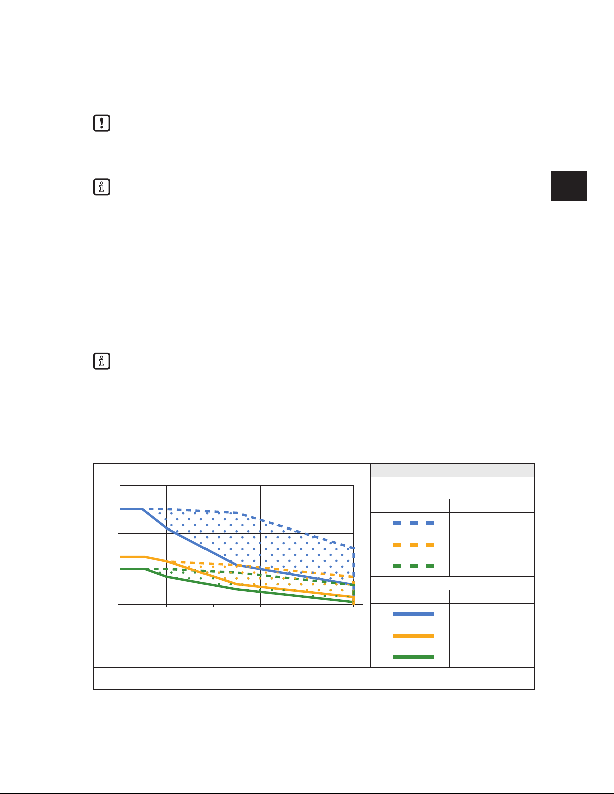
6.2.1 Typical warning limits for O3D301 / O3D303
0
5
10
15
0 2 4 6 8 10
x
y
20
25
Parameter "Max. background distance"
Installation on heat-conductive metal parts
with heat conductor (→ 6.2.3)
Warning limit Parameter
< 5 m
< 30 m
> 30 m
Normal installation
Warning limit Parameter
< 5 m
< 30 m
> 30 m
x = exposure time [ms]
y = frame rate [fps]
Page 8
3D camera
8
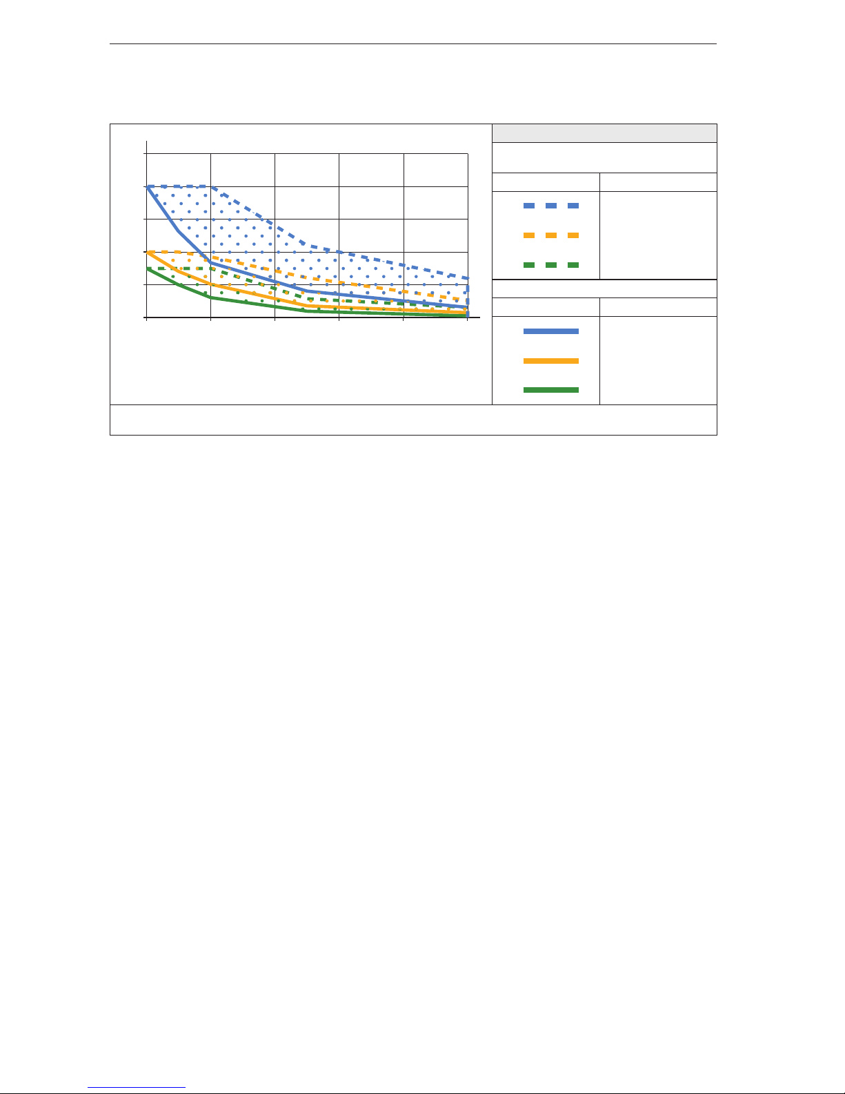
6.2.2 Typical warning limits for O3D311 / O3D313
0
5
10
15
0 2 4 6 8 10
x
y
20
25
Parameter "Max. background distance"
Installation on heat-conductive metal parts
with heat conductor (→ 6.2.3)
Warning limit Parameter
< 5 m
< 30 m
> 30 m
Normal installation
Warning limit Parameter
< 5 m
< 30 m
> 30 m
x = exposure time [ms]
y = frame rate [fps]
6.2.3 Reduce surface temperature
With the following measures the surface temperature can be reduced:
► Mount the camera on heat-conductive metal parts.
> A large-surface contact of the camera with metal parts increases heat dissipation (e.g. aluminium).
► Use a heat conductor when mounting the camera on metal parts.
> The heat-conductive effect is increased by means of the heat conductor. The heat conductor is
available as accessories (→ 6.4).
► Reduce obstructions around the camera. Reduce the density of objects mounted near to the camera.
> Obstructions around the camera and a high installation density may have a negative impact on
convection (air movement).
► Mount one or two heat sinks on the camera.
> The heat sinks increase the surface of the camera, reducing the surface temperature. The heat sinks
are available as accessories (→ 6.4).
► Reduce exposure time, frame rate or max. background distance.
> The operating mode used and the parameters can increase the surface temperature.
Page 9

9
3D camera
UK
6.3 Install camera
Observe the following instructions when installing the camera:
► Mount the camera using 2x M5 screws or mounting set.
> The bore dimensions for the M5 screws are indicated in the data sheet.
> The mounting set is available as accessories (→ 6.4).
► Use strain reliefs for all cables connected to the camera.
Observe the following instructions when installing an O3D301 and O3D311:
► Mount the camera so that the focus adjustment screw can be accessed with a screw driver.
> The position of the focus adjustment screw is indicated in the scale drawing (→ 12).
If the device is permanently used in wet areas, the nut of the M12 Industrial Ethernet cable
(e.g. E11898) may corrode. Use a cable with a high-grade stainless steel nut for permanent use in
wet areas.
6.4 Mounting accessories
Depending on the location and type of installation, you can use the following mounting accessories:
Article number Description
E3D301 Mounting set Smart Camera
E3D302 Cooling Element Smart Camera
E3D303 Heat conductor Smart Camera
E3D304 2x Cooling Element Smart Camera
You can find more information about the accessories at:
www.ifm.com
→ Data sheet search → e.g. O3D303 → Accessories
Page 10
3D camera
10
7. Electrical connection
Observe the following instructions before electrical installation.
NOTICE
The camera must be connected by a qualified electrician. Observe the electrical data in the data sheet.
Camera of protection class III (PC III)
The electric supply must only be made via PELV circuits.
Electric supply must correspond to UL61010-1, chapter 9.4 - Limited Energy:
The overcurrent protection device must switch off a current of 6.6 A in 120 s. For the correct rating of the
overcurrent protection device take the technical data of the camera and wiring into account.
The separation of external circuits must comply with UL61010-2-201, fig. 102.
For cable lengths > 30 m use an additional protection against surge voltages to IEC 6100-4-5.
Disconnect power before connecting the camera.
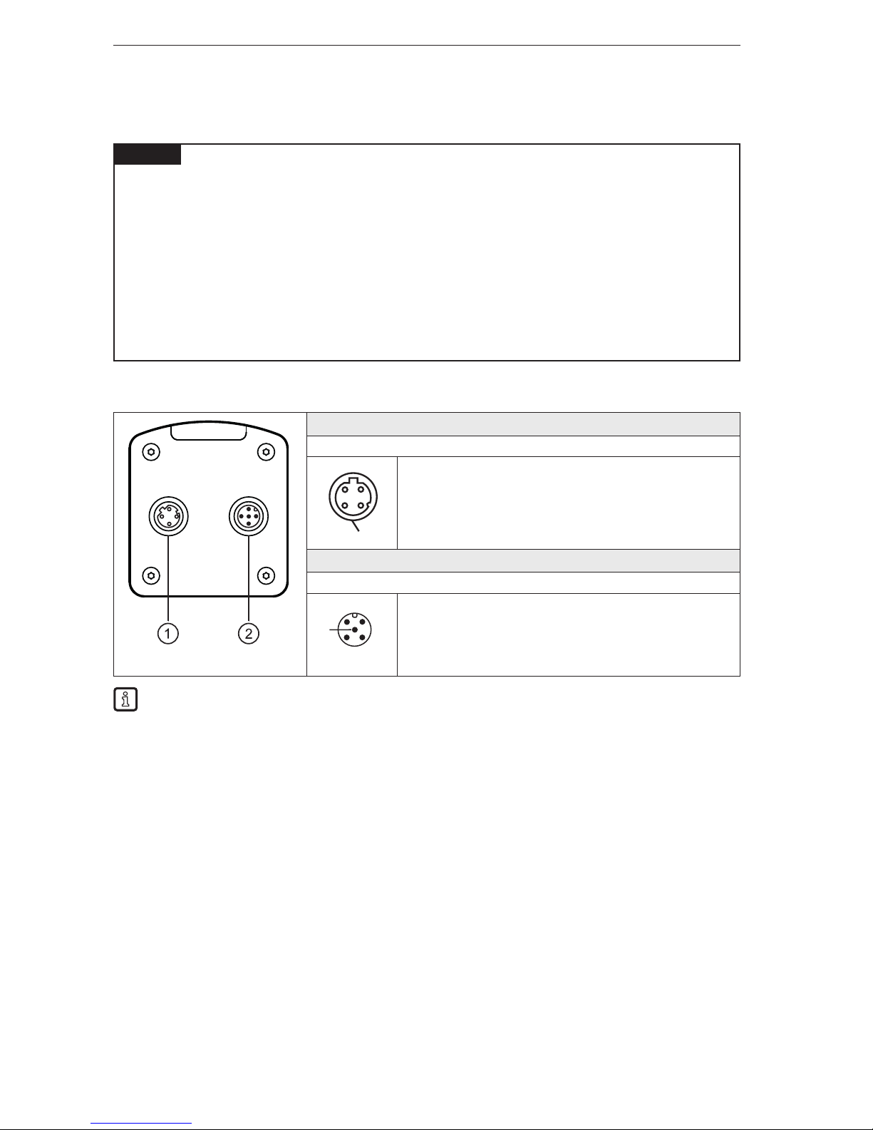
7.1 Wiring
① Ethernet
M12 socket, D-coded, 4 poles
1 TD +
2 RD +
3 TD 4 RD S Shield
② Power supply
M12 connector, A-coded, 5 poles
4
2 1
3
5
1 U+
2 trigger input
3 GND
4 switching output 1 - ready
5 switching output 2 - cascading
The behaviour of the switching inputs and outputs can be set with the software ifm Vision Assistant.
The setting PNP or NPN always applies to all switching inputs and outputs.
When installing actuators and sensors make sure that the setting is correct (e.g. photoelectric
sensors for triggering).
The switching outputs can also be operated as pulse outputs which reset their switching signal
after an adjustable time.
Page 11
11
3D camera
UK
7.1.1 Pin 1 / 3 (24 V / GND)
The permissible voltage range is indicated in the data sheet of the camera.
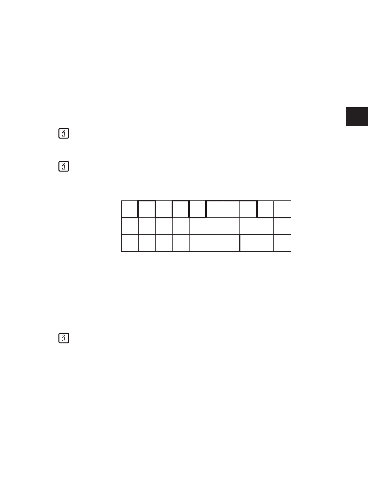
7.1.2 Pin 2 (trigger input)
The image capture of the camera can be triggered with a switching signal via the trigger input.
The following trigger edges can be used:
● Falling edge triggers image capture
● Rising edge triggers image capture
● Falling and rising edges trigger image capture
Further possibilities to trigger the camera:
● Process interface commands (→ 13.3)
● Continuous image capture with fixed frame rate
The trigger input is internally debounced. Depending on the electrical installation debouncing of the
trigger wire is not necessary.
Internal debouncing prevents several short pulses from triggering. The pulse must be at least 2 ms
long to be recognised as a trigger.
7.1.3 Pin 4 / 5 (ready / cascading)
The electrical data of the switching outputs 1 and 2 (ready / cascading) is indicated in the data sheet.
The switching outputs provide the following camera status set as default:
● Switching output 1: "Ready for trigger"
● Switching output 2: "Image capture finished"
"Switching output switched" means that the respective camera status has occurred.
Depending on the setting the camera status can have one of the following values:
● "Ready for trigger"
The camera signals that a new image can be captured. Only with this camera status trigger operations
are processed. For the continuous image capture the camera status "Ready for trigger" is not output.
● "Image capture finished"
The camera signals that the image capture is finished. The camera status can be used for cascading
cameras.
● "Evaluation finished"
The camera signals that image processing is finished. At that moment the switching outputs are
already updated. The image data is transmitted via Ethernet.
● "Error"
The camera signals an internal error. Detailed information about errors can be requested via Ethernet.
image capture
Trigger input
Time [ms]
1 2 3 4 5 6 7 8 9 10 11
Page 12
3D camera
12
7.2 Wiring examples
Wiring examples of the camera are given below.
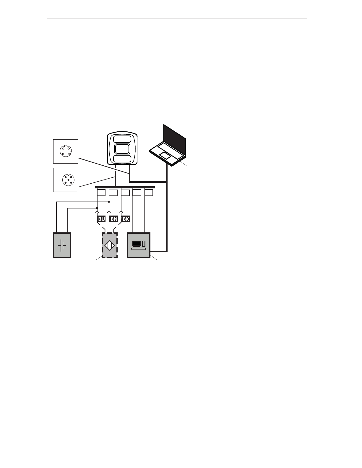
7.2.1 Trigger image capture with proximity sensor
The camera can be triggered externally:
● via Ethernet
● via a proximity sensor connected to the trigger input
The following illustration shows the wiring of the camera with a proximity sensor.
3 1 2 4 5
1 2
34
4
2 1
3
5
DC 24 V
+
-
IN IN
①
② ③
①: Notebook (parameter setting)
②: Proximity sensor
③: Industrial PC (evaluate / trigger)
Page 13
13
3D camera
UK
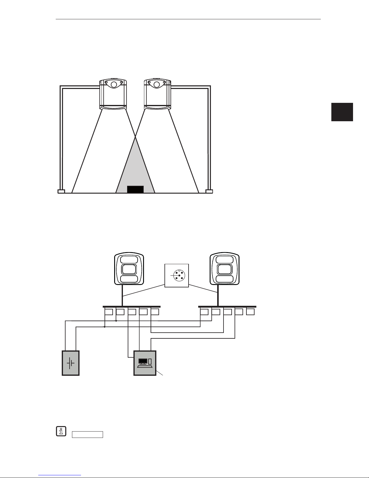
7.2.2 Install several cameras next to each other
Cameras installed next to each other can cause measurement errors due to simultaneous exposure.
①: 1st camera
②: 2nd camera
③: Object
The measurement errors can be avoided in two ways:
● Cascade cameras via HW trigger
During cascading a controller triggers the image capture of the 1st camera. After completion of the
image capture the 1st camera automatically triggers the 2nd camera. The 2nd camera signals the end
of the sequence to the controller.
3 1 2 4 5
4
2 1
3
5
DC 24 V
+
-
IN IN
3 1 2 4 5
①
①: Industrial PC
(evaluate /
trigger)
● Use different frequency channels
With the software ifm Vision Assistant each camera can be assigned its own frequency channel. The
different frequency channels reduce the occurrence of measurement errors.
The ifm Vision Assistant software is available free of charge on our website:
www.ifm.com
→ Service → Download → Industrial imaging
①
②
③
Page 14
3D camera
14
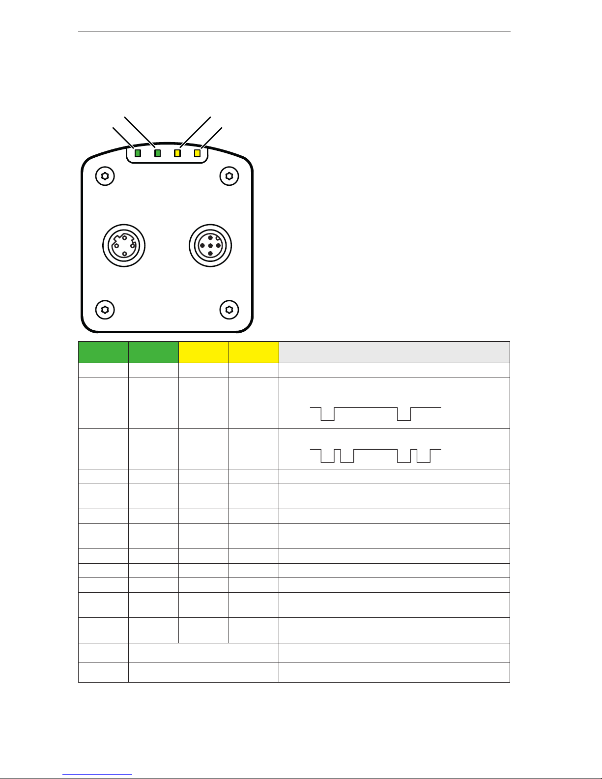
8. Indicators
Via the LED indicators 1 - 4 the camera signals the current operating state.
LED 4
(Ethernet)
LED 1
(Power)
LED 2
(Out 1)
LED 3
(Out 2)
Description
Lights Camera is ready for operation, supply voltage applied
Flashes
at 0.5 Hz
No parameters set or parameter setting was not
loaded into the camera
On
Off
Flashes
2x at 0.5
Hz
Camera is in the parameter setting mode
On
On
Off
Off
Lights Switching output 1 switched
Flashes
at 8 Hz
Switching output 1 shorted
Lights Switching output 2 switched
Flashes
at 8 Hz
Switching output 2 shorted
Lights Ethernet connected
Flashes Ethernet transmitting data
Off Ethernet not connected
Flashes
at 8 Hz
Flashes
at 8 Hz
Camera signals internal error
Flashes
at 2 Hz
Flashes
at 2 Hz
Camera signals correctable error. The error information
can be read via Ethernet
Running light ⇒
Camera booting
Running light ⇐
Camera carrying out firmware update
LED 4 LED 3
LED 1 LED 2
Page 15
15
3D camera
UK
9. Set-up
After power on the camera is put into operation. After 15 seconds the camera is in the evaluation mode
where saved applications are executed. The indicators signal the current operating state (→ 8).
Up to 32 applications can be saved on the camera. Typically, an application contains the following
parameters:
● Image capture: e.g. triggering of the image capture, exposure time, image processing filter
● Interface: Ethernet, switching outputs
The respective application can be activated with the software ifm Vision Assistant or via process
interface commands.
9.1 Set parameters of the camera
The camera parameters can be set in two ways:
● Software ifm Vision Assistant (→ see software manual)
● XML-RPC command (→ 13.5)
The software ifm Vision Assistant and detailed information about the measuring principle of the
camera are described in the software manual.
The software manual is available on our website:
www.ifm.com
→ Data sheet search → e.g.
O3D303 → Operating instructions
9.2 Detect object
The conditions which lead to a high detection rate of objects are described below.
①: Camera
②: Zone of influence
③: Field of view
④: Object
Optimum detection of an object ④ is given if the following conditions are met:
● Object is positioned in the field of view ③
● Object is the nearest visible object to the camera ①
● Zone of influence ② is clear from objects (obstructions etc.)
● Lens window of the camera is free from soiling.
If the conditions are not met, measurement errors may occur.
③
②
④
②
①
Page 16

3D camera
16
10. Maintenance, repair and disposal
Observe the following instructions:
► Do not open the housing as the camera does not contain any components which can be maintained by
the user. The camera must only be repaired by the manufacturer.
► Dispose of the camera in accordance with the national environmental regulations.
10.1 Clean
Observe the following instructions before cleaning the camera:
► Use clean and lint-free cloth.
► Use glass cleaner as cleaning agent.
If the instructions are not observed, scratches on the lens window may cause measurement errors.
10.2 Update firmware
With the software ifm Vision Assistant the firmware of the camera can be updated.
Parameters saved in the camera get lost by the firmware update. Create a backup copy of the
parameters before updating the firmware:
► Before updating the firmware export parameters.
► After updating the firmware import parameters.
Firmware updates are available on our website:
www.ifm.com
→ Service → Download → Industrial imaging
10.3 Replace camera
When a camera is replaced the parameters get lost. Before replacing the camera create a backup copy of
the parameters:
► Before replacement export the parameters of the old camera.
► After replacement import the parameters into the new camera.
With the export and import of parameters several cameras can be quickly provided with the same
parameters.
11. Approvals/standards
The CE declaration of conformity is available at:
www.ifm.com
→ Data sheet search → e.g. O3D303 → Approvals
Page 17
17
3D camera
UK
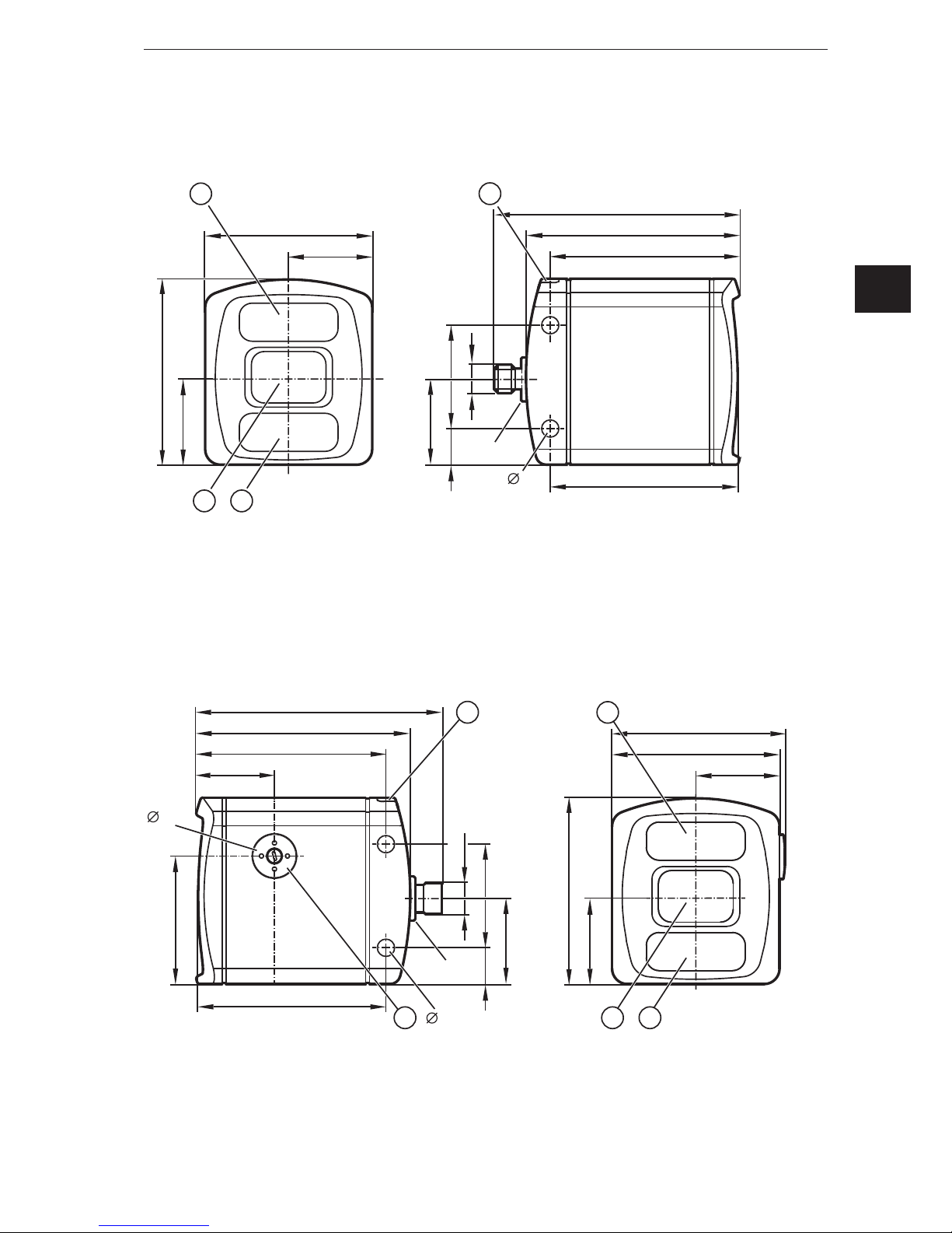
12. Scale drawings
12.1 O3D303 / O3D313
①: Lens
②: Illumination unit
③: LED 2 colours (yellow/green)
12.2 O3D301 / O3D311
①: Lens
②: Illumination unit
③: LED 2 colours (yellow/green)
④: Focal setter
Original Scale Drawing (MTD)
33
3
5,7
M12x1
4014
95
82,6
73,3
71,6
72
65
32,5
21
33
2
M12x1
Original Scale Drawing (MTD)
33
3
5,7
M12x1
4014
95
82,6
73,3
71,6
49
17,1
28,7
4
M12x1
72
65
32,5
2
21
33
67,1
Page 18

3D camera
18
13. Appendix
13.1 Required Ports
The following ports are required for the camera configuration using XML-RPC and for receiving data on
the process interface. They must not be blocked by a firewall or router.
● TCP/HTTP: 80
● TCP: 50010
If the ifm Vision Assistant is used, the following additional ports must also be available:
● UDP: 3321
● TCP/HTTP: 8080
It is possible to configure another port than 50010 for the process interface. If a different port is used, it
must not be blocked either.
13.2 XML-RPC Interface
In case the O3D3xx camera should not be configured by the “ifmVisionAssistant”, the XML-RPC interface
can be used instead.
General information about XML-RPC is found on the website http://xmlrpc.scripting.com/spec
To send a command via the XML-RPC interface the command has to be in a special layout. In this
command, linefeeds and carriage returns are essential.
Every command which has to be sent via the XML-RPC interface must end with
carriage return <CR> and linefeed <LF>.
Several commands will use different URLs in the XML-RPC header.
13.2.1 Sample XML-RPC command
All following XML-RPC commands will have this type of layout:
POST /RPC3 HTTP/1.0<CR><LF>
User-Agent: Frontier/5.1.2 (WinNT)<CR><LF>
Host: betty.userland.com<CR><LF>
Content-Type: text/xml<CR><LF>
Content-length: 181<CR><LF>
<CR><LF>
<?xml version="1.0"?><CR><LF>
<methodCall><CR><LF>
<methodName>examples.getStateName</methodName><CR><LF>
<params><CR><LF>
<param><CR><LF>
<value><i4>41</i4></value><CR><LF>
</param><CR><LF>
</params><CR><LF>
</methodCall><CR><LF>
Page 19

19
3D camera
UK
The following example contains one O3D3xx command:
POST /api/rpc/v1/com.ifm.efector/ HTTP/1.1 <CR><LF>
User-Agent: Frontier/5.1.2 (WinNT)<CR><LF>
Host: 192.168.0.69<CR><LF>
Content-Type: text/xml<CR><LF>
Content-length: 94<CR><LF>
<CR><LF>
<?xml version="1.0"?><CR><LF>
<methodCall><CR><LF>
<methodName>getParameter</methodName><CR><LF>
</methodCall><CR><LF>
13.2.2 XML-RPC Objects
To communicate and to configure the device via XML-RPC the XML-RPC commands have to use
different XML-RPC objects. Different commands need different XML-RPC objects (see XML-RPC
command references).
The interface of O3D3xx is structured in an object-oriented way. Some of the objects are available all
the time, others are only available after bringing the device into a special mode by calling a method
on an already available object. This mechanism is used to create system requirements (e.g. password
protection).
It could be necessary to send heartbeats so that there will be no session timeout.
The following diagram should give an overview how objects are related to each other and which methods
must be called to make others available:
Main API
Session
EditMode
ApplicationConfig
requestSession(...)
setOperatingMode(1)
editApplication(1)
DeviceConfig
NetworkConfig
ImagerConfig
Page 20

3D camera
20
Main Object
Object-URI: /api/rpc/v1/com.ifm.efector/
This is the main object of RPC. It contains methods to open a session. The session contains methods for
activating the edit mode. Most of its methods are only getters, because it should be possible to protect
editing with a password.
Session Object
Object URI e.g.: /api/rpc/v1/com.ifm.efector/session_d21c80db5bc1069932fbb9a3bd841d0b/
The URL part “d21c80db5bc1069932fbb9a3bd841d0b” is the session ID. It is returned by the command
"requestSession" of the main object. If the command "requestSession" is called without a user-defined
session ID, which can be passed as a parameter, a random session ID is generated automatically.
EditMode Object
Object URI e.g.: /api/rpc/v1/com.ifm.efector/session_d21c80db5bc1069932fbb9a3bd841d0b/edit/
This object is only available if the device is in the edit operating mode. The index of applications must be
between 1 and 32. The device must only support 32 applications and the indexes must start at 1.
DeviceCong Object
Object-URI e.g.: /api/rpc/v1/com.ifm.efector/session_d21c80db5bc1069932fbb9a3bd841d0b/edit/device/
Device/NetworkCong Object
Object URI e.g.:
/api/rpc/v1/com.ifm.efector/session_d21c80db5bc1069932fbb9a3bd841d0b/edit/device/network/
Application Cong Object (editable application)
Object URI e.g.:
/api/rpc/v1/com.ifm.efector/session_d21c80db5bc1069932fbb9a3bd841d0b/edit/application/
Main API
Session
EditMode
ApplicationConfig
cancelSession(...) removes itself from RPC. Session will also
be removed, if heartbeat(...) is not called at the right time
setOperatingMode(0) will remove EditMode from RPC
stopEditApplication() will remove ApplicationConfig from RPC
Page 21

21
3D camera
UK
Application/Imager Cong Object (O3D3xx)
Object URI e.g.:
/api/rpc/v1/com.ifm.efector/session_d21c80db5bc1069932fbb9a3bd841d0b/edit/application/imager_001/
As there is only one imager config on O3D3xx, the ID must be fixed to "001". Data of this object is
persistently saved when calling "save" on the application config object. The imager config RPC object
has multiple sub-types. Only parameters relevant for a specific type are available while it is active. They
are based on frequency (extending the distance) and integration intervals (extending the measurement
details).
Type names, based on GUI draft (under 5 metres -> single frequency, up to 30 metres -> double
frequency, more than 30 metres -> triple frequency.):
under5m_low
under5m_moderate
under5m_high
upto30m_low
upto30m_moderate
upto30m_high
morethan30m_low
morethan30m_moderate
Image Settings and Filter Parameters
There is an RPC object for spatial filter parameters in each imager configuration.
Object URI e.g.: /api/rpc/v1/com.ifm.efector/session_d21c80db5bc1069932fbb9a3bd841d0b/edit/
application/imager_001/spatialfilter
There is an RPC object for temporal filter parameters in each imager configuration.
Object URI e.g.: /api/rpc/v1/com.ifm.efector/session_d21c80db5bc1069932fbb9a3bd841d0b/edit/
application/imager_001/temporalfilter
Data of these objects is persistently saved when calling "save" on application config object.
Page 22

3D camera
22
13.3 Process Interface
The process interface is used during the normal operation mode to get operational data (e.g. 3D images,
process values) from the O3D3xx.
13.3.1 Sending Commands
For sending commands via the process interface the commands have to be sent with a special protocol
and as ASCII character strings. This protocol conforms to the version 3 of the O2V/O2D products.
Structure of the protocol:
<Ticket><length>CR LF <Ticket><content>CR LF
Abbreviation Description ASCII code (dec) ASCII code (hex)
CR Carriage Return 13 D
LF Linefeed 10 A
< > Marking of a placeholder
(e.g. <code> is a placeholder for code)
[ ] Optional argument
(possible but not required)
Command Description
<content> It is the command to the device (e.g. trigger the unit).
<ticket> It is a character string of 4 digits between 0-9. If a message with a specific ticket is sent
to the device, it will response with the same ticket.
<length> It is a character string beginning with the letter 'L' followed by 9 digits. It indicates the
length of the following data (<ticket><content>CR LF) in bytes.
They are different protocol versions available:
Version Input format Output format
V1 <Content>CR LF as input
V2 <Ticket><Content>CR LF as input
V3 <Ticket><Length>CR+LF<Ticket><Content>CR LF as input
V4 <Content>CR LF <length>CR LF<Content>CR LF
The default protocol version is "V3". It is recommended to use protocol version 3 for machine
to machine communication. This is due to the fact that only version 3 supports asynchronous
messages and provides length information.
13.3.2 Receiving Images
For receiving the image data a TCP/IP socket communication has to be established. The default port
number is 50010. The port number may differ based on the configuration. After opening the socket
communication, the O3D3XX device will automatically (if the device is in free run mode) send the data
through this socket to the TCP/IP client (PC).
PCIC output per frame. The following data shall be submitted in this sequence:
Component Content
Ticket and length information (→ 13.4.2)
Ticket „0000“
Start sequence String "star" (4 bytes)
Normalised amplitude image
Output format: 16-bit unsigned integer
1 image
Page 23

23
3D camera
UK
Component Content
Distance image
Output format: 16-bit integer. Unit: mm.
1 image
X image
Output format: 16-bit signed integer. Unit:
mm.
1 image
Y image
Output format: 16-bit signed integer. Unit:
mm.
1 image
Z image
Output format: 16-bit signed integer. Unit:
mm.
1 image
Confidence image
Output format: 8-bit unsigned integer
1 image
Diagnostic data
Stop sequence String "stop" (4 bytes)
Ticket signature <CR><LF>
13.3.3 Image data
For every image there will be a separate chunk. The chunk is part of the response frame data of the
process interface.
The header of each chunk contains different kinds of information. This information is separated into bytes.
The information contains e.g. the kind of image which will be in the “PIXEL_DATA” and the size of the
chunk.
Chunk type:
Offset Name Description Size [byte]
0x0000 CHUNK_TYPE Defines the type of the chunk. For each distinct chunk
an own type is defined.
4
0x0004 CHUNK_SIZE Size of the whole image chunk in bytes. After this count
of bytes the next chunk starts.
4
0x0008 HEADER_SIZE Number of bytes starting from 0x0000 until PIXEL_
DATA.
4
0x000C HEADER_VERSION Version number of the header 4
0x0010 IMAGE_WIDTH Image width in pixel 4
0x0014 IMAGE_HEIGTH Image height in pixel 4
0x0018 PIXEL_FORMAT Pixel format 4
0x001C TIME_STAMP Time stamp in microseconds 4
0x0020 FRAME_COUNT Frame counter 4
0x0024 PIXEL_DATA The pixel data in the given type and dimension of the
image. Padded to 4-byte boundary.
4
Page 24

3D camera
24
Available chunk types:
Constant Value Description
USERDATA 0 Undefined user data with arbitrary content
RADIAL_DISTANCE_
IMAGE
100 Each pixel of the distance matrix denotes the ToF distance
measured by the corresponding pixel or group of pixels of
the imager. The distance value is corrected by the camera's
calibration, excluding effects caused by multipath and multiple
objects contributions (e.g. "flying pixels"). Reference point is the
optical centre of the camera inside the camera housing.
Invalid PMD pixels (e.g. due to saturation) have a value of zero.
Data type: 16-bit unsigned integer (little endian)
Unit: millimetres
NORM_AMPLITUDE_
IMAGE
101 Each pixel of the normalized amplitude image denotes the raw
amplitude (see amplitude image below for further explanation),
normalized to exposure time. Furthermore, vignetting effects
are compensated, ie the darkening of pixels at the image border
is corrected. The visual impression of this grayscale image is
comparable to that of a common 2D camera.
Invalid PMD pixels (e.g. due to saturation) have an amplitude value
of 0.
Data type: 16-bit unsigned integer
AMPLITUDE_IMAGE 103 Each pixel of the amplitude matrix denotes the amount of
modulated light (i.e. the light from the camera's active illumination)
which is reflected by the appropriate object. Higher values indicate
higher PMD signal strengths and thus a lower amount of noise on
the corresponding distance measurements. The amplitude value
is directly derived from the PMD phase measurements without
normalisation to exposure time. In multiple exposure mode,
the lack of normalisation may lead (depending on the chosen
exposure times) to inhomogeneous amplitude image impression, if
a certain pixel is taken from the short exposure time and some of
its neighbours are not.
Invalid PMD pixels (e.g. due to saturation) have an amplitude value
of 0.
Data type: 16-bit unsigned integer
CARTESIAN_X_
COMPONENT
200 The X matrix denotes the X component of the Cartesian coordinate
of a PMD 3D measurement. The origin of the camera's coordinate
system is in the middle of the lens' front glass, if the extrinsic
parameters are all set to 0.
Data type: 16-bit signed integer
Unit: millimetres
CARTESIAN_Y_
COMPONENT
201 The Y matrix denotes the Y component of the Cartesian coordinate
of a PMD 3D measurement. The origin of the camera's coordinate
system is in the middle of the lens' front glass, if the extrinsic
parameters are all set to 0.
Data type: 16-bit signed integer
Unit: millimetres
Page 25

25
3D camera
UK
Constant Value Description
CARTESIAN_Z_
COMPONENT
202 The Z matrix denotes the Z component of the Cartesian coordinate
of a PMD 3D measurement. The origin of the camera's coordinate
system is in the middle of the lens' front glass, if the extrinsic
parameters are all set to 0.
Data type: 16-bit signed integer
Unit: millimetres
CARTESIAN_ALL 203 CARTESIAN_X_COMPONENT,
CARTESIAN_Y_COMPONENT,
CARTESIAN_Z_COMPONENT
UNIT_VECTOR_ALL 223 The unit vector matrix contains 3 values [ex, ey, ez] for each PMD
pixel, i.e. the data layout is [ex_1,ey_1,ez_1, ... ex_N, ey_N,
ez_N], where N is the number of PMD pixels.
Data type: 32-bit floating point number (3x per pixel)
CONFIDENCE_IMAGE 300 See Additional Information for Image Data (→ 13.3.4)
DIAGNOSTIC 302 See Receiving Images (→ 13.3.2)
Pixel format:
Constant Value Description
FORMAT_8U 0 8-bit unsigned integer
FORMAT_8S 1 8-bit signed integer
FORMAT_16U 2 16-bit unsigned integer
FORMAT_16S 3 16-bit signed integer
FORMAT_32U 4 32-bit unsigned integer
FORMAT_32S 5 32-bit signed integer
FORMAT_32F 6 32-bit floating point number
FORMAT_64U 7 64-bit unsigned integer
FORMAT_64F 8 64-bit floating point number
Reserved 9 N/A
FORMAT_32F_3 10 Vector with 3x32-bit floating point number
Page 26

3D camera
26
13.3.4 Additional Information for CONFIDENCE_IMAGE
Further information for the confidence image:
Bit Value Description
0 1 = pixel invalid Pixel invalid
The pixel is invalid. To determine whether a pixel is valid or not
only this bit needs to be checked. The reason why the bit is
invalid is recorded in the other confidence bits.
1 1 = pixel saturated Pixel is saturated
Contributes to pixel validity: yes
2 1 = bad A-B symmetry A-B pixel symmetry
The A-B symmetry value of the four phase measurements is
above threshold.
Remark: This symmetry value is used to detect motion
artefacts. Noise (e.g. due to strong ambient light or very short
integration times) or PMD interference may also contribute.
Contributes to pixel validity: yes
3 1 = amplitude below
minimum amplitude
threshold
Amplitude limits
The amplitude value is below minimum amplitude threshold.
Contributes to pixel validity: yes
4+5 Bit 5, bit 4
0 0 = unused
0 1 = shortest exposure
time (only used in 3
exposure mode)
1 0 = middle exposure
time in 3 exposure mode,
short exposure in double
exposure mode
1 1 = longest exposure
time (always 1 in single
exposure mode)
Exposure time indicator
The two bits indicate which exposure time was used in a
multiple exposure measurement.
Contributes to pixel validity: no
6 N/A Currently not used
7 1 = suspect/defective pixel Suspect pixel
This pixel has been marked as "suspect" or "defective" and
values have been replaced by interpolated values from the
surroundings.
Contributes to pixel validity: no
Page 27

27
3D camera
UK
13.3.5 Conguration of PCIC Output
The user has the possibility to define his own PCIC output. This configuration is only valid for the current
PCIC connection. It does not affect any other connection and will get lost after disconnecting.
For configuring the PCIC output a “flexible” layouter concept is used, represented by a JSON string. The
format of the default configuration is as follows:
{
"layouter": "flexible",
"format": { "dataencoding": "ascii" },
"elements": [
{ "type": "string", "value": "star", "id": "start_string" },
{ "type": "blob", "id": "normalized_amplitude_image" },
{ "type": "blob", "id": "X_image" },
{ "type": "blob", "id": "Y_image" },
{ "type": "blob", "id": "Z_image" },
{ "type": "blob", "id": "confidence_image" },
{ "type": "blob", "id": "diagnostic_data" },
{ "type": "string", "value": "stop", "id": "end_string" }
]
}
This string can be retrieved by the C? command, altered and sent back using the c command.
The layout software has the following main object properties:
Name Description Details
layouter Defines the basic data output format.
So far only “flexible” is supported
Type: string
format Defines format details, the definitions in the main object are
the defaults for any of the following data elements (e.g. if it
says dataencoding=binary, all data elements should be binary
encoded instead of ASCII).
Type: object
elements List of data elements which must be written. Type: array of objects
The actual data is defined within the “elements” properties and may consist of these settings:
Name Description Details
type Defines the type of data which must be written.
The data might be stored in a different type (e.g. stored as integer but
should be output as Float32)
The type "records" will need some special handling.
Type: string
id Defines an identifier for this data element.
If there is no fixed value (property "value"), the data should be
retrieved via id.
Type: string
value Optional property for defining a fixed output value. Type: any JSON value
format Type-depending option for fine-tuning the output format.
E.g. cut an integer to less than 4 bytes.
Type: object
Page 28

3D camera
28
Available values for the type property:
Type Description
records Defines that this element represents a list of records.
If type is set to "records", there must be an "elements" property.
The "elements" property defines which data should be written per record.
string Data is written as string.
Most of the time this will be used with "value" property to write fixed start, end or delimiter
text.
Text encoding should be UTF8 if there is nothing else specified in format properties.
float32 Data is written as floating point number.
This has a lot of formatting options (at least with "flexible" layout software)
See following section about format properties.
uint32 Data is written as integer.
This has a lot of formatting options (at least with "flexible" layout software)
See following section about format properties.
int32 Data is written as integer.
This has a lot of formatting options (at least with "flexible" layout software)
See following section about format properties.
uint16 Limits the output to two bytes in binary encoding, besides the binary limitation it acts like
uint32.
int16 Limits the output to two bytes in binary encoding, besides the binary limitation it acts like
int32.
uint8 Limits the output to one byte in binary encoding, besides the binary limitation it acts like
uint32.
int8 Limits the output to one byte in binary encoding, besides the binary limitation it acts like
int32.
blob Data is written as a BLOB (byte by byte as if it came from the data provider).
(Binary Large Object)
Depending on the desired data format the user may tune his output data with further “format” properties.
Common format properties:
Format
properties
Allowed values Default
dataencoding "ascii" or "binary" can be defined in top-level-object and
overwritten by element objects.
"ascii"
scale "float value with decimal separator" to scale the results for
output byte width
1.0
offset "float value with decimal separator" 0.0
Binary format properties:
Format properties Allowed values Default
order Little, big and network Little
Page 29

29
3D camera
UK
ASCII format properties:
Format properties Allowed values Default
width Output width. If the resulting value exceeds the width field the
result will not be truncated.
0
fill Fill character " "
precision Precision is the number of digits behind the decimalseparator. 6
displayformat Fixed, scientific Fixed
alignment Left, right Right
decimalseparator 7-bit characters for e.g. "." "."
base Defines if the output should be:
● binary (2)
● octal (8)
● decimal (10)
● hexadecimal (16)
10
Example of a format configuration of the temperature (id: temp_illu) element.
1. Illumination temperature like this "33,5___":
c000000226{ "layouter": "flexible", "format": { "dataencoding": "ascii" },
"elements": [ { "type": "float32", "id": "temp_illu", "format": { "width": 7,
"precision": 1, "fill": "_", "alignment": "left", "decimalseparator": "," }
} ] }
2. Illumination temperature as binary (16-bit integer, 1/10 °C):
c000000194{ "layouter": "flexible", "format": { "dataencoding": "ascii"
}, "elements": [ { "type": "int16", "id": "temp_illu", "format": {
"dataencoding": "binary", "order": "network", "scale": 10 } } ] }
3. Illumination temperature in °F (e.g. "92.3 Fahrenheit" ):
c000000227{ "layouter": "flexible", "format": { "dataencoding": "ascii" },
"elements": [ { "type": "float32", "id": "temp_illu", "format": { "precision":
1, "scale": 1.8, "offset": 32 } }, { "type": "string", "value": " Fahrenheit"
} ] }
Page 30

3D camera
30
The following element IDs are available:
ID Description Native datatype
evaltime Evaluation time for current frame in milliseconds 32-bit unsigned
integer
framerate Current frame rate in Hz Float32
temp_front1 Temperature measured in the device while capturing this
result.
Measured by first sensor on imager board.
Float32, unit: °C"
temp_illu Temperature measured in the device while capturing this
result.
Measured on the illumination board.
Float32, unit: °C
extrinsic_calibration Extrinsic calibration, constisting of 3 translation
parameters (unit: millimeters) and 3 angles
(unit: degree): [t_x, t_y, t_z, alpha_x, alpha_y, alpha_z]
Float32
amplitude_image PMD raw amplitude image 16-bit unsigned
integer
normalized_amplitude_
image
Normalized amplitude image 16-bit unsigned
integer
distance_image Radial distance image. 16-bit unsigned
integer
unit: millimetres
x_image
y_image
z_image
Cartesian coordinates for each pixel.
Each dimension is a separate image.
16-bit signed
integer
all_cartesian_vector_
matrices
All Cartesian images (X+Y+Z) concatenated to one
package
16-bit signed
integer
confidence_image Confidence image 8-bit unsigned
integer
all_unit_vector_matrices Matrix of unit vectors. Each element consists of a
3 component vector [e_x, e_y, e_z]
Float32
Page 31

31
3D camera
UK
13.4 Process Interface Command Reference
All received messages which are sent because of the following commands will be sent without
“start”/”stop” at the beginning or ending of the string.
13.4.1 t Command (Asynchronous Trigger)
Command
t
Description Executes trigger. The result data
is send asynchronously
Type Action
Reply * Trigger was executed, the device
captures an image and evaluates
the result.
! ● Device is busy with an
evaluation
● Device is in an invalid state
for this command, e.g.
configuration mode
● Device is set to a different
trigger source
● No active application
13.4.2 T? Command (Synchronous Trigger)
Command
T?
Description Executes trigger. The result data
is send synchronously
Type Request
Reply Process data within the
configured layout
Trigger was executed, the device
captures an image, evaluates
the result and sends the process
data.
! ● Device is busy with an
evaluation
● Device is in an invalid state
for this command, e.g.
configuration mode
● Device is set to a different
trigger source
● No active application
13.4.3 I? Command
Command
I<image-ID>?
Description Request last image taken
Type Request
Reply <length><image data>
! ● No image available
● Wrong ID
? ● Invalid command length
Page 32

3D camera
32
Note <image-ID>
2 digits for the image type
<length>
char string with exactly 9 digits
as decimal number for the image
data size in bytes
<image data>
image data
Valid image ID:
01- amplitude image
02 - normalised amplitude image
03 - distance image
04 – X image (distance
information)
05 – Y image (distance
information)
06 – Z image (distance
information)
07 - confidence image (status
information)
08 - extrinsic calibration
09 - unit_vector_matrix_ex, ey,ez
10 - last result output as
formatted for this connection
11 - all distance images: X, Y,
and Z
13.4.4 p Command
Command
p<state>
Description Turns the PCIC output on or off
Type Action
Reply *
! <state> contains wrong value
? Invalid command length
Note <state> 1 digit
0: deactivates all asynchronous
output
1: activates asynchronous result
output
2: activates asynchronous error
output
3: activates asynchronous error
and data output
On device restart the value
configured within the application
is essential for the output of data.
This command can be executed
in any device state.
Page 33

33
3D camera
UK
13.4.5 a Command
Command
a<application number>
Description Activates the selected
application
Type Action
Reply *
! ● Application not available
● <application number>
contains wrong value
● External application switching
activated
● Device is in an invalid state
for this command, e.g.
configuration mode
? Invalid command length
Note <application number>
2 digits for the application
number as decimal value
13.4.6 A? Command
Command
A?
Description Requests the occupancy of the
application list
Type Request
Reply <amount><t><number active
application><t>
...
<number><t><number>
? Invalid command length
! Invalid state (e.g. no application
active)
Note <amount>
char string with 3 digits for the
amount of applications saved on
the device as decimal number
<t>
tabulator (0x09)
<number active application>
2 digits for the active application
<number>
2 digits for the application
number
The active application is
repeated within the application
list.
Page 34

3D camera
34
13.4.7 v Command
Command
v<version>
Description Sets the current protocol version.
The device configuration is not
affected
Type Action
Reply *
! Invalid version
? Invalid command length
Note <version>
2 digits for the protocol version
(→ 13.3.1)
The default protocol version is „V3“.
13.4.8 V? Command
Command
V?
Description Requests current protocol
version
Type Request
Reply <current version><empty><min
version><empty><max version>
Note <current version>
2 digits for the currently set
version
<empty>
space sign: 0x20
<min/max version>
2 digits for the available min and
max version that can be set
13.4.9 c Command
Command
c<length><configuration>
Description Uploads a PCIC output
configuration lasting this session
Type Action
Reply *
! ● Error in configuration
● Wrong data length
? Invalid command length
Note <length>
9 digits as decimal value for the
data length
<configuration>
configuration data
Page 35

35
3D camera
UK
13.4.10 C? Command
Command
C?
Description Retrieves the current PCIC
configuration
Type Request
Reply <length><configuration>
? Invalid command length
Note <length>
9 digits as decimal value for the
data length
<configuration>
configuration data
13.4.11 S? Command
Command
S?
Description Requests current decoding
statistics
Type Request
Reply <number of
results><t><number of positive
decodings><t><number of false
decodings>
! No application active
Note <t>
tabulator (0x09)
<number of results>
Images taken since application
start. 10 digits decimal value with
leading 0s
<number of positive decodings>
Number of decodings leading
to a positive result. 10 digits
decimal value with leading 0s
<number of false decodings>
Number of decodings leading
to a negative result. 10 digits
decimal value with leading 0s
Page 36

3D camera
36
13.4.12 G? Command
Command
G?
Description Requests device information
Type Request
Reply <vendor><t><article number><t>
<name><t><location><t><descri
ption><t><ip>
<subnet mask><t><gateway><
t><MAC><t><DHCP><t><port
number>
Note ● <vendor>
IFM ELECTRONIC
● <t>
Tabulator (0x09)
● <article number>
e.g. O3D300
● <name>
UTF8 Unicode string
● <location>
UTF8 Unicode string
● <description>
UTF8 Unicode string
● <ip>
IP address of the device as
ASCII character sting
e.g. 192.168.0.96
● <port number>
port number of the XML-RPC
● <subnet mask>
subnet mask of the device as
ASCII
e.g. 192.168.0.96
● <gateway>
gateway of the device as
ASCII
e.g 192.168.0.96
● <MAC>
MAC adress of the device as
ASCII
e.g. AA:AA:AA:AA:AA:AA
● <DHCP>
ASCII string "0" for off and
"1" for on
Page 37

37
3D camera
UK
13.4.13 H? Command
Command
H?
Description Returns a list with available
commands
Type Request
Reply H? - show this list
t - execute Trigger
T? - execute Trigger and wait for
data
o<io-id><io-state> - sets IO state
O<io-id>? - get IO state
I<image-id>? - get last image of
defined type
A? - get application list
p<state> - activate / deactivate
data output
a<application number> - set
active application
V? - get current protocol version
v<version> - sets protocol
version
c<length of configuration
file><configuration file> configures process date
formatting
C? - show current configuration
G? - show device information
S? - show statistics
L? - retrieves the connection ID
Page 38

3D camera
38
13.5 XML-RPC Command Reference
13.5.1 Parameter API
The parameters setParameter, getParameter, getAllParameters and getAllParameterLimits are
implemented in the following RPC objects:
● Device
● Network
● Application
● ImagerConfig
● Filter
● Model
setParameter
Method name
setParameter
Description Sets a parameter to a specific value
Input parameters 1. Name of parameter:string
2. New value: string
Output parameters Empty string (compatibility with classic XmlRPC client)
getParameter
Method name
getParameter
Description Returns the current value of the parameter
Input parameters Name of parameter: string
Output parameters Value of parameter: string
getAllParameters
Method name
getAllParameters
Description Returns all parameters of the object in one data structure
Input parameters None
Output parameters 1. Struct (name contains the parameter name, value contains the
stringified parameter value)
getAllParameterLimits
Method name
getAllParameterLimits
Description Returns limits of all numeric parameters, that have limits defined on
the device
Input parameters None
Output parameters 1. Struct of Structs (name in first struct is the parameter name,
substructs contains: min :string, max :string)
E.g.
{"ExposureTime1": { "min": "123", "max": "432" },
"ExposureTime2": { "min": "123", "max": "432" }}
Page 39

39
3D camera
UK
Parameter string encoding
Non-string parameters must be encoded in the following format.
Type Stringified
bool "true" / "false"
setParameter method also accepts "1"/"0", getter methods must always return
"true"/"false"
int decimal ( e.g "-1234" / "1234" )
Values should be in the range of int32 (-2^31 .. 2^31)
double English floating point notation (optional with exponent)
E.g. "1.2", ".3", "4.5e6", "-7E-8", "-inf", "nan"
Structured types (array or structs) can't be put into parameter storage in an general way. Encoding
of arrays must specified on specific parameters.
13.5.2 Main Object
getParameter
Method name
getParameter
Description Getter for the device-global parameters
Input parameters Name of a device parameter: string
Output parameters Value of the requested parameter: string
getAllParameters
Method name
getAllParameters
Description Getter for the parameters described here.
This is an additional getter outside of edit sessions, so it is possible
to read device information without login.
Input parameters none
Output parameters Struct (name contains the parameter name, value contains the
stringified parameter value)
Page 40

3D camera
40
getSWVersion
Method name
getSWVersion
Description Returns version information of all software components
Input parameters none
Output parameters Struct of strings (e.g. { "IFM_Software": "0.01.07", "Frontend":
"01.05.02", ... } )
*mandatory keys:
"IFM_Software"
"Linux"
"Main_Application"
"Diagnostic_Controller"
"Algorithm_Version"
"Calibration_Version"
"Calibration_Device"
getHWInfo
Method name
getHWInfo
Description Returns hardware information of all components
Input parameters none
Output parameters Struct of strings ( e.g. { "MACAddress": "00:02:01:40:06:C9",
"Frontend": "#!01_F340_001_...", ... } )
*mandatory keys:
"MACAddress"
"Connector"
"Diagnose"
"Frontend"
"Illumination"
"Mainboard"
getApplicationList
Method name
getApplicationList
Description Delivers basic information of all applications stored on the device.
Input parameters none
Output parameters Array of structs (Index: int, Id: int, Name: string, Description: string)
Page 41

41
3D camera
UK
requestSession
Method name
requestSession
Description Requests a session object for access to the configuration and for
changing the device operating mode.
This blocks parallel editing and allows protection of editing with a
password.
The ID could optionally be defined by the external system but it must
be the defined format (32char "hex").
If it is called with only one parameter, the device will generate a
session ID.
The session will start with a default timeout ("SessionTimeout"
device parameter), the timeout can be extended by calling
"heartbeat".
The device will stay in RUN mode.
If password is disabled on the device, the value given as password
parameter is ignored.
Input parameters 1. Password: string
2. Session ID: string (optional)
Output parameters Session ID: string
reboot
Method name
reboot
Description Reboot system, parameter defines which mode/system will be
booted
Input parameters Type of system that should be booted after shutdown: int
0: Productive mode
1: Recovery mode
Output parameters Output: string
systemCommand
Method name
systemCommand
Description Performs a generic command on the device.
Input parameters 1. Command: string
2. Parameter: string
Output parameters Output: string
Page 42

3D camera
42
13.5.3 Session Object
heartbeat
Method name
heartbeat
Description Extends the life time of the edit session.
If the given value is outside the range of "SessionTimeout", the
saved default timeout will be used.
Input parameters Requested timeout interval till next heartbeat, in seconds: int
Output parameters The used timeout interval, in seconds: int
cancelSession
Method name
cancelSession
Description Explicit stop of this session
If an application is still in edit mode, it will implicitly do the same as
"stopEditingApplication".
Input parameters none
Output parameters Empty string (compatibility with classic XmlRPC-client)
exportCong
Method name
exportConfig
Description Exports the whole configuration of the sensor device
Input parameters none
Output parameters Configuration as a data BLOB: binary/base64
importCong
Method name
importConfig
Description Imports whole configuration with the option to skip specific parts
Input parameters 1. Configuration as a data BLOB: binary/base64
2. Flags describing which parts should be loaded:
0x0001: Includes configuration (Name, Description, Location, ...)
0x0002: Includes network configuration (IP, DHCP, ...)
0x0010: Includes all application configurations
Output parameters Empty string (compatibility with classic XmlRPC-client)
exportApplication
Method name
exportApplication
Description Exports one application config
Input parameters Application index
Output parameters Application config as a data BLOB: binary/base64
Page 43

43
3D camera
UK
importApplication
Method name
importApplication
Description Imports an application config and creates a new application with it.
The device will put the new application on the first free index.
Input parameters Application config as one data BLOB: binary/base64
Output parameters Index of new application
setOperatingMode
Method name
setOperatingMode
Description Changes the operating mode of the device.
Setting this to "edit" will enable the "edit mode object” on RPC.
Input parameters Mode: integer
0: Run mode
1: Edit mode
Output parameters Empty string (compatibility with classic XmlRPC-client)
Page 44

3D camera
44
13.5.4 Edit Mode Object
factoryReset
Method name
factoryReset
Description Resets all configurations to factory settings
Input parameters none
Output parameters Empty string (compatibility with classic XmlRPC-client)
A factory reset will delete all applications which are saved on the camera.
editApplication
Method name
editApplication
Description Puts a specified application into the edit status.
This will attach an application object to the RPC interface.
The name of the object will be application independent.
This does not change the "ActiveApplication" parameter.
Input parameters Application index: int
Output parameters Empty string (compatibility with classic XmlRPC-client)
stopEditingApplication
Method name
stopEditingApplication
Description Tells the device that editing this application was finished.
Unsaved changes are discarded.
Input parameters none
Output parameters Empty string (compatibility with classic XmlRPC-client)
createApplication
Method name
createApplication
Description Creates an "empty" application. The embedded side should initialise
all needed parameters and structures.
Input parameters none
Output parameters Index of new application: int
Page 45

45
3D camera
UK
copyApplication
Method name
copyApplication
Description Creates a new application by copying the configuration of another
application.
The device will generate an ID for the new application and put it on
a free index.
Input parameters Index of the application which should be copied: int
Output parameters Index of new application: int
deleteApplication
Method name
deleteApplication
Description Deletes the application from sensor
If the deleted application was the active one, the sensor will have no
active application anymore until the user picks one.
Input parameters Index of application: int
Output parameters Empty string (compatibility with classic XmlRPC-client)
moveApplications
Method name
moveApplications
Description Moves applications to other index.
There must be all applications in the new list, none of them
duplicated and no index used twice.
The ID is a fixed value that stays the same as long as the
application stays on the sensor.
The index could be changed and is used to address the application
via PCIC, XML-RPC and digital IO.
Input parameters Array of structs (Id: int, Index: int)
Output parameters Empty string (compatibility with classic XmlRPC-client)
13.5.5 Device Cong Object
activatePassword
Method name
activatePassword
Description Sets a password and activates it for the next edit session.
Making this change persistently requires to call "save" on device
config.
Input parameters Password: string
Output parameters Empty string (compatibility with classic XmlRPC-client)
Page 46

3D camera
46
disablePassword
Method name
disablePassword
Description Disables the password protection.
Making this change persistently requires to call "save" on device
config.
Input parameters none
Output parameters Empty string (compatibility with classic XmlRPC-client)
save
Method name
save
Description Stores current configuration in persistent memory.
If this is not called after changing device parameters (via
setParameter), changes will get lost on reboot.
Input parameters none
Output parameters Empty string (compatibility with classic XmlRPC-client)
Parameters of device cong
Methods for parameter access are defined here:
Parameter name Data type Description
Name String (utf8) User-defined name of the device (max. 64 characters).
Description String (utf8) User-defined description of the device
(max. 500 characters).
ActiveApplication Int
*has limits
Index of active application
This applies only to RUN mode:
* defines the application active on startup (if staticapplication switching is disabled)
* contains the current active application (could also be
changed via PCIC command)
* 0 means no application is active
PcicTcpPort Int TCP/IP port for PCIC connections.
PcicProtocolVersion Int
*has limits
Sub-protocol of PCIC, see specification of PCIC.
IOLogicType Int
*has limits
Defines logic type of all digital pins.
Allowed values:
0: NPN
1: PNP
IODebouncing Bool Applies to all inputs
IOExternApplicationSwitch Int
*has limits
Allowed values:
0: off
1: static via I/O
2: pulse driven via I/O
3: pulse driven via trigger
Page 47

47
3D camera
UK
Parameter name Data type Description
SessionTimeout Int
*has limits
Number of seconds which a session stays before a call
to "heartbeat" method is needed
ServiceReportFailedBuffer Int
*has limits
Number of buffers reserved for failed results
ServiceReportPassedBuffer Int
*has limits
Number of buffers reserved for passed results
ExtrinsicCalibTransX Double
Unit: millimetres
Extrinsic calibration, transition in X direction
ExtrinsicCalibTransY Double
Unit: millimetres
Extrinsic calibration, transition in Y direction
ExtrinsicCalibTransZ Double
Unit: millimetres
Extrinsic calibration, transition in Z direction
ExtrinsicCalibRotX Double
Unit: degrees
Extrinsic calibration, rotation around X axis
ExtrinsicCalibRotY Double
Unit: degrees
Extrinsic calibration, rotation around Y axis
ExtrinsicCalibRotZ Double
Unit: degrees
Extrinsic calibration, rotation around Z axis
IPAddressConfig Int readonly: The GUI requires to know if the device is on
a discovery IP address for multiple-use cases. This
information was extended to reflect all kinds of IPaddress situations.
Allowed values:
0: Static (IP address explicitly defined inside the
device)
1: DHCP (using a DHCP server in the network)
2: LinkLocal (configured to DHCP, but no server which
provided an address)
3: Discovery (changed by IP4Discovery mechanism)
PasswordActivated Bool readonly: Is true if the password protection is enabled
OperatingMode Int readonly: Mode of device (RUN, EDIT)
see "setOperatingMode" (the setter is outside the edit
mode but inside session)
DeviceType String readonly: Delivers a type description, unique by
imager, evaluation logic and device interface.
ArticleNumber String readonly: Official catalogue number
ArticleStatus String readonly: Official two-letter status code
UpTime Double readonly: Hours since last reboot
ImageTimestampReference Int
Unit:
microseconds
readonly: This returns the current timestamp as a
reference for the timestamps in the received images.
TemperatureFront1 Double
Unit: celsius
readonly: Temperature measured in the device.
Measured by first sensor on imager board.
Page 48

3D camera
48
Parameter name Data type Description
TemperatureFront2 Double
Unit: celsius
readonly: Temperature measured in the device.
Measured by second sensor on imager board.
TemperatureIllu Double
Unit: celsius
readonly: Temperature measured in the device.
Measured on the illumination board.
*has limits: parameters with this marker are listed in the reply of getAllParameterLimits method.
Default values of device cong parameters
The default values of the device configuration parameters are:
Parameter name Data type Description
Name String (utf8) "New sensor"
Description String (utf8) ""
ActiveApplication Int
*has limits
0
PcicTcpPort Int 50010
PcicProtocolVersion Int
*has limits
3
IOLogicType Int
*has limits
1
IODebouncing Bool true
IOExternApplicationSwitch Int
*has limits
0
SessionTimeout Int
*has limits
30
ExtrinsicCalibTransX Double
Unit: millimetres
0.0
ExtrinsicCalibTransY Double
Unit: millimetres
0.0
ExtrinsicCalibTransZ Double
Unit: millimetres
0.0
ExtrinsicCalibRotX Double
Unit: degrees
0.0
ExtrinsicCalibRotY Double
Unit: degrees
0.0
ExtrinsicCalibRotZ Double
Unit: degrees
0.0
IPAddressConfig Int 0
PasswordActivated Bool false
OperatingMode Int 0
ServiceReportFailedBuffer Int 15
ServiceReportPassedBuffer Int 15
For all other device config parameters there are no defined default values because they are either devicedependent (DeviceType, ArticleNumber, ArticleStatus) or volatile (UpTime, ImageTimestampReference).
Page 49

49
3D camera
UK
Minimum and maximum values of device cong parameters
The minimum and maximum values of the device configuration parameters are:
Parameter name Minimum value Maximum value
ActiveApplication 0 32
PcicProtocolVersion 1 4
IOLogicType 0 1
IOExternApplicationSwitch 0 3
SessionTimeout 5 300
13.5.6 Device/Network Cong Object
saveAndActivateCong
Method name
saveAndActivateConfig
Description Reinitialise the network interface so that it uses the configuration
which was set by the other RPC methods.
There will be no XMLRPC reply because the network interface is
instantly reset.
Input parameters none
Output parameters Empty string (compatibility with classic XmlRPC-client)
13.5.7 Application Cong Object
save
Method name
save
Description Stores current configuration in persistent memory.
This is also be possible if the application is not yet in an "activatable"
status.
Input parameters none
Output parameters Empty string (compatibility with classic XmlRPC-client)
forceTrigger
Method name
forceTrigger
Description Executes a software trigger of currently active application.
Input parameters none
Output parameters Empty string (compatibility with classic XmlRPC-client)
Validate
Method name
validate
Description Validates the application. This means it checks if the application can
be activated.
Input parameters none
Output parameters Array of fault structs (Id: int, Text: string)
Fault scenarios none
Page 50

3D camera
50
Parameters of application
Methods for parameter access are defined here:
Parameter name Data type Description
Name String (utf8) User-defined name of the application
(max. 64 characters).
Description String (utf8) User-defined description of the application
(max. 500 characters).
TriggerMode Int
*has limits
Allowed values:
1: free run
2: process interface
3: positive edge
4: negative edge
5: positive and negative edge
PcicTcpResultOutputEnabled Bool Allows to disable the automatic output of results via
PCIC.
If it is false, PCIC commands could be used to access
the data again.
PcicTcpResultSchema String It defines which images and result data will be sent.
It will also define the order of data elements and
additional separators.
Contains single-enabling/disabling of AmplitudeImage,
IntensityImage, DistanceImage, XImage, YImage,
ZImage, ConfidenceImage, DiagnosticData (→ 13.3.5)
LogicGraph String JSON string describing a flow graph which allows to
program the logic between model results and output pins.
Type String Internal use
TemplateInfo String A generic JSON storage, where the GUI could store
additional data about the used template GUI (versions
and additional parameter decisions).
This data should not be used by the device, it should only
be stored on the device.
*has limits: parameters with this marker are listed in the reply of getAllParameterLimits method
Default values of application parameters
The default values of application parameters are:
Parameter name Data type Description
Name String (utf8) "new application"
Description String (utf8) ""
TriggerMode Int
*has limits
1
PcicTcpResultOutputEnabled Bool true
PcicTcpResultSchema String ""
LogicGraph String ""
Type String "Camera"
TemplateInfo String ""
Page 51

51
3D camera
UK
Minimum and maximum values of application parameters
The minimum and maximum values of application parameters are:
Parameter name Minimum value Maximum value
TriggerMode 1 5
13.5.8 Application/Imager Cong Object
changeType
Method name
changeType
Description Changes the type of imager configuration.
This changes setting of available parameters and might also change
available RPC methods.
Input parameters Type: string
Output parameters Empty string (compatibility with classic XmlRPC-client)
availableTypes
Method name
availableTypes
Description Lists all available imager configuration types.
Input parameters none
Output parameters Array of strings
Parameters of all types of application imager cong
Methods for parameter access are defined here:
Parameter name Data type Description
Type String readonly: Type of imager configuration, see Change
Type Method
FrameRate Double
*has limits
Target frame rate in frames per second for free run
mode.
ClippingLeft Double
*has limits
Lower value of clipping area in width
ClippingTop Double
*has limits
Lower value of clipping area in height
ClippingRight Double
*has limits
Upper value of clipping area in width
ClippingBottom Double
*has limits
Upper value of clipping area in height
ContinuousAutoExposure Bool Enables the continuous adaptation of the
integration time during decoding
Page 52

3D camera
52
Parameter name Data type Description
SpatialFilterType Int
*has limits
Allowed values:
0: off
1: median filter
2: mean filter
3: bilateral filter
TemporalFilterType Int
*has limits
Allowed values:
0: off
1: temporal mean filter
2: adaptive exponential filter
EnableFilterDistanceImage Bool Activates the filter for the distance image
EnableFilterAmplitudeImage Bool Activates the filter for the amplitude image
EnableAmplitudeCorrection Bool Enables the correction of the amplitude values
EnableRectificationDistanceImage Bool Enables the rectification of the distance image
EnableRectificationAmplitudeImage Bool Enables the rectification of the normalized
amplitude image
ExposureTimeList String readonly: A list of all current exposure times
separated by ";"
It should contain 3 values in "*_high" types,
2 values in "*_moderate" types and 1 value in
"*_low" types. The list is sorted in ascending order.
*has limits: parameters with this marker are listed in the reply of getAllParameterLimits method
Default values of common imager cong parameters
The default values of the common imager configuration parameters are:
Parameter name Data type Description
Type String "under5m_low"
FrameRate Double 5.0
ContinuousAutoExposure Bool false
SpatialFilterType Int 0
TemporalFilterType Int 0
EnableFilterDistanceImage Bool true
EnableFilterAmplitudeImage Bool true
EnableAmplitudeCorrection Bool true
EnableRectificationDistanceImage Bool false
EnableRectificationAmplitudeImage Bool false
Minimum and maximum values of common imager cong parameters
The minimum and maximum values of the common imager configuration parameters are:
Parameter name Minimum value Maximum value
FrameRate 0.0167 30.0
SpatialFilterType 0 3
AverageFilterNumPictures 1 25
TemporalFilterType 0 2
Page 53

53
3D camera
UK
Parameters only in "under5m_low"-type of application imager cong
Parameter name Data type Description
ExposureTime Int
*has limits
Time for the exposure
The 2nd exposure time will be calculated based on the
first one.
ExposureTimeRatio Int
*has limits
Ratio of long exposure time to short exposure time.
Channel Int
*has limits
Allowed values:
0: non-group use (like channel1 but additional GUI
option)
1: channel1
2: channel2
3: channel3
Default values of the "under5m_low" mode parameters
Parameter name Data type Default value
ExposureTime Int 1000
Channel Int 0
Minimum and maximum values of the "under5m_low" mode parameters
Parameter name Minimum value Maximum value
ExposureTime 0 10000
Channel 0 3
Parameters only in "under5m_moderate"-type of application imager cong
Parameter name Data type Description
ExposureTime Int
*has limits
Time for the long exposure
The 2nd exposure time will be calculated based on the first
one.
Channel Int
*has limits
Allowed values:
0: non-group use (like channel1)
1: channel1
2: channel2
3: channel3
Page 54

3D camera
54
Default values of the "under5m_moderate" mode parameters
Parameter name Data type Default value
ExposureTime Int 1000
ExposureTimeRatio Int 40
Channel Int 0
Minimum and maximum values of the "under5m_moderate" mode parameters
Parameter name Minimum value Maximum value
ExposureTime 0 10000
ExposureTimeRatio 2 50
Channel 0 3
Parameters only in "under5m_high"-type of application imager cong
Parameter name Data type Description
Channel Int
*has limits
Allowed values:
0: non-group use (like channel1 but additional GUI option)
1: channel1
2: channel2
3: channel3
Default values of the "under5m_high" mode parameters
Parameter name Data type Default value
Channel Int 0
Minimum and maximum values of the "under5m_high" mode parameters
Parameter name Minimum value Maximum value
Channel 0 3
Parameters only in "upto30m_low"-type of application imager cong
Parameter name Data type Description
ExposureTime Int
*has limits
Time for the long exposure
Channel Int
*has limits
Allowed values:
0: non-group use (like channel1)
1: channel1
2: channel2
3: channel3
Page 55

55
3D camera
UK
Default values of the "upto30m_low" mode parameters
Parameter name Data type Default value
ExposureTime Int 1000
Channel Int 0
Minimum and maximum values of the "upto30m_low" mode parameters
Parameter name Minimum value Maximum value
ExposureTime 0 10000
Channel 0 3
Parameters only in "upto30m_moderate"-type of application imager cong
Parameter name Data type Description
ExposureTime Int
*has limits
Time for the long exposure
The 2nd exposure time will be calculated based on the first
one.
ExposureTimeRatio Int
*has limits
Ratio of long exposure time to short exposure time
Channel Int
*has limits
Allowed values:
0: non-group use (like channel1 but additional GUI option)
1: channel1
2: channel2
3: channel3
Default values of the "upto30m_moderate" mode parameters
Parameter name Data type Default value
ExposureTime Int 1000
ExposureTimeRatio Int 40
Channel Int 0
Minimum and maximum values of the "upto30m_moderate" mode parameters
Parameter name Minimum value Maximum value
ExposureTime 0 10000
ExposureTimeRatio 2 50
Channel 0 3
Page 56

3D camera
56
Parameters only in "upto30m_high"-type of application imager cong
Parameter name Data type Description
Channel Int
*has limits
Allowed values:
0: non-group use (like channel1 but additional GUI option)
1: channel1
2: channel2
3: channel3
Default values of the "upto30m_high" mode parameters
Parameter name Data type Default value
Channel Int 0
Minimum and maximum values of the "upto30m_high" mode parameters
Parameter name Minimum value Maximum value
Channel 0 3
13.5.9 Image Settings and Filter Parameters
To set the spatial or temporal filter use the general “setter” method.
Parameters of spatial median, spatial mean and spatial bilateral lter
Parameter name Data type Description
MaskSize Int Allowed values:
0: 3x3
1: 5x5
Parameters of temporal mean lter
Parameter name Data type Description
NumberOfImages Int Limit: 2..25
 Loading...