

Page 1

Seite 1 von 72
Operations Manual
3D camera
O3D303
Page 2

Seite 2 von 72
1 PRELIMINARY NOTE ................................................................ 5
2 SAFETY INSTRUCTIONS ........................................................... 5
3 FUNCTIONS AND FEATURES ...................................................... 5
4 INSTALLATION ....................................................................... 6
4.1 Object distance ................................................................................ 6
4.2 Camera surroundings ....................................................................... 6
4.3 Heat dissipation ............................................................................... 7
5 LED DISPLAY ........................................................................ 8
6 ELECTRICAL CONNECTION........................................................ 9
6.1 Wiring .............................................................................................. 10
7 XML-RPC INTERFACE ............................................................ 11
7.1 Sample XML-RPC command .............................................................. 11
7.2 XML-RPC Objects ............................................................................. 12
7.2.1 Main-Object: ........................................................................... 14
7.2.2 SessionObject ......................................................................... 14
7.2.3 EditMode-Object ...................................................................... 14
7.2.4 DeviceConfig-Object ................................................................ 14
7.2.5 Device/NetworkConfig-Object .................................................... 14
7.2.6 ApplicationConfig-Object (editable application) ........................... 14
7.2.7 App./ImagerConfig-Object (O3D3xx) .......................................... 15
7.2.8 Image-Settings Filter-Parameter ................................................ 15
8 PROCESS INTERFACE .............................................................. 16
8.1 Sending commands .......................................................................... 16
8.2 Receiving images ............................................................................. 18
8.3 Image data ....................................................................................... 20
8.4 Additional information for image data ............................................... 25
8.5 Configuration of PCIC output............................................................ 27
8.6 Sample C++ Code for setting up a socket .......................................... 32
9 XML-RPC COMMAND REFERENCES ............................................ 33
Page 3

Seite 3 von 72
9.1 "setParameter" must be implemented on all RPC-objects which offer parameter
33
9.2 Main-Object ..................................................................................... 33
9.2.1 "getParameter” ........................................................................ 33
9.2.2 "getAllParameters" .................................................................. 33
9.2.3 "getSWVersion" ....................................................................... 34
9.2.4 "getHWInfo" ............................................................................ 35
9.2.5 "getApplicationList”.................................................................. 35
9.2.6 "requestSession" ..................................................................... 36
9.2.7 "reboot" .................................................................................. 36
9.2.8 "systemCommand” ................................................................... 36
9.3 Session-Object ................................................................................. 37
9.3.1 "heartbeat" ............................................................................. 37
9.3.2 "cancelSession”....................................................................... 37
9.3.3 "exportConfig” ......................................................................... 37
9.3.4 "importConfig” ......................................................................... 38
9.3.5 "exportApplication” .................................................................. 38
9.3.6 "importApplication” .................................................................. 38
9.3.7 "setOperatingMode" ................................................................. 39
9.4 EditMode-Object............................................................................... 40
9.4.1 "factoryReset" ......................................................................... 40
9.4.2 "editApplication" ...................................................................... 40
9.4.3 "stopEditingApplication" ........................................................... 40
9.4.4 "createApplication" .................................................................. 41
9.4.5 "copyApplication" .................................................................... 41
9.4.6 "deleteApplication" .................................................................. 41
9.4.7 "moveApplications" .................................................................. 42
9.5 DeviceConfig-Object ........................................................................ 43
9.5.1 "activatePassword" .................................................................. 43
9.5.2 "disablePassword" ................................................................... 43
9.5.3 "save" .................................................................................... 43
9.5.4 Parameters ............................................................................. 44
9.6 Device/NetworkConfig-Object ........................................................... 49
Page 4

Seite 4 von 72
9.6.1 "saveAndActivateConfig" .......................................................... 49
9.7 ApplicationConfig-Object ................................................................. 49
9.7.1 "save" .................................................................................... 49
9.7.2 "forceTrigger" .......................................................................... 49
9.7.3 "validate" ................................................................................ 50
9.7.4 Parameters ............................................................................. 51
9.8 App./ImgagerConfig-Object .............................................................. 53
9.8.1 "changeType" .......................................................................... 53
9.8.2 "availableTypes" ...................................................................... 53
9.8.3 Parameters ............................................................................. 54
9.9 Image-Settings Filter-Parameter ....................................................... 61
9.9.1 Parameters ............................................................................. 61
10 PROCESS INTERFACE COMMAND REFERENCE ............................... 63
10.1 t command ....................................................................................... 63
10.2 T? command .................................................................................... 63
10.3 I? command ..................................................................................... 64
10.4 p command ...................................................................................... 65
10.5 a command ...................................................................................... 65
10.6 A? command .................................................................................... 66
10.7 v command ...................................................................................... 67
10.8 V? command .................................................................................... 67
10.9 c command ...................................................................................... 68
10.10 C? command .................................................................................... 68
10.11 S? command .................................................................................... 69
10.12 L? command .................................................................................... 70
10.13 G? command .................................................................................... 71
10.14 H? command .................................................................................... 72
Page 5

Seite 5 von 72
1 PRELIMINARY NOTE
This document is intended for specialists. These specialists are people who are qualified
by their appropriate training and their experience to see risks and to avoid possible hazards that may be caused during operation or maintenance of the device. The document contains information about the correct handling of the device.
Read this document before use to familiarise yourself with operating conditions and installation. Keep this document during the entire duration of use of the device.
2 SAFETY INSTRUCTIONS
This instruction is part of the device. It contain texts and figures concerning the correct
handling of the device and must be read before installation or use.
Note the safety instructions. Use the device in accordance with its designated use.
The installation and connection must comply with the applicable national and international
standards. Responsibility lies with the person installing the device.
Only the signals indicated in the technical data or on the device label may be supplied to
the connections or wires.
The unit may only be opened by the manufacturer or by a person authorised by the manufacturer.
3 FUNCTIONS AND FEATURES
The O3D303 3D camera is an optical camera equipped with an internal illumination unit
measuring the distance between the camera and the nearest surface point by point.
The data is used to describe the captured scene three-dimensionally.
The data is issued and the device parameters are set via Ethernet.
The unit may only be used under the environmental conditions specified in the data sheet.
The device safety is rated for use under the following environmental conditions:
• Indoor use
• Altitudes up to 2000 m
• Relative air humidity up to max. 90%, non condensing
• Pollution degree 3
Page 6

Seite 6 von 72
4 INSTALLATION
► Use cables with strain relief.
4.1 Object distance
► Choose the mounting position of the camera so that the object of interest is completely
located within the field of view of the camera. Make allowances for positioning tolerances.
The field of view may be found in the product data sheet. The lateral dimensions of the
camera image increase linearly with the distance from the camera, i.e. the field of view increases with increasing distance.
► The distance between camera and object must not exceed the maximum measuring
range and should be within the operating distance stated in the product data sheet.
► The distance between the camera and the object of interest should be chosen as small
as possible in order to measure the object with maximum resolution.
4.2 Camera surroundings
► For best measurement accuracy the object of interest (C) should be the object closest
to the camera within the field of view (B).
► Objects which are located close to the field of view (area A) may lead to measurement
errors and should be avoided. This also includes mounting posts, clamps, etc.
Page 7

Seite 7 von 72
► Bright extraneous light such as e.g. sun light incident on the surface of the object of
interest or on the camera lens should be avoided. Only the infrared portion of the light between 800nm and 900nm is critical and should not exceed the sunlight-equivalent of 8klux.
► The camera optics must be kept clean. Avoid installation in heavy polluting areas of a
machine. Mounting the camera facing down may help to reduce collection of dust on the
front window.
► Do not install the camera behind windows. Direct reflection from the camera illumination
back into the camera lens may lead to measurement errors. Such reflections are present
even at very clean glass surfaces.
4.3 Heat dissipation
ATTENTION
Depending on the operating mode, the unit may heat up.
The difference between the unit's surface temperature and the ambient temperature may
not exceed 25 degrees. Take one or several of the following measures:
► Preferably mount camera to large metal parts which are good heat conductors such as
e.g. aluminium. A good thermal contact between camera and camera mounting increases
the dissipation of excess heat. A heat conducting plate is available as separate accessory.
► Allow the circulation of air around the camera to allow thermal convection. Mounting
positions directly under a roof or in cramped areas may lead to heat accumulation.
► Thermal convection may be further improved by using one or two heat dissipators which
are available as separate accessories.
► The camera temperature may also be reduced by reducing the following operation parameters of the camera:
- frame rate
- exposure time
- maximum measurement distance (number of used frequencies)
► Use a contact protection.
Page 8
Seite 8 von 72
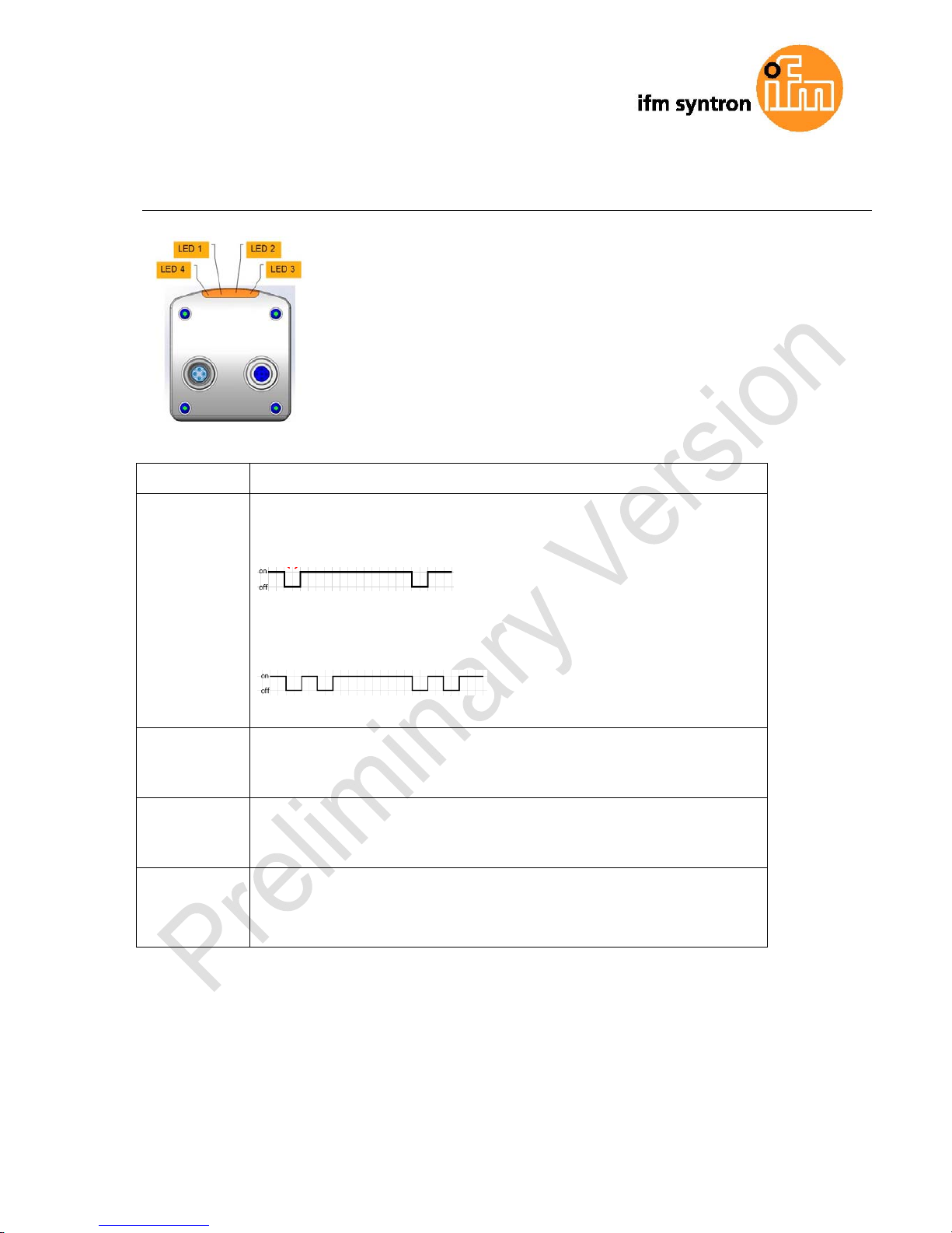
5 LED DISPLAY
LED behaviour, device status
LED 1
Power
(green)
ON: supply voltage available, device ready for operation
flashing (0,5 Hz)
:
No parametrisation available.
flashing (0,5 Hz)
setup mode
LED 2
Out1
(yellow)
ON: switching output 1 is on
flashing (8Hz): short circuit switching output 1
LED 3
Out2
(yellow)
ON: switching output 1 is on
flashing (8Hz): short circuit switching output 2
LED 4
Ethernet
(green)
OFF: no ethernet connection
ON: ethernet connection
flashing: ethernet communication
Other status displayed by LEDs:
- LED 2 and 3 (both yellow) flash simultaneously (8 Hz) internal error
- LED 2 and 3 flash simultaneously (2 Hz) repairable error, please note ethernet error
message
- Sequence flashing LED 1, 2 und 3 device is booting
- Sequence flashing LED 3, 2 und 1 firmware update
Page 9
Seite 9 von 72
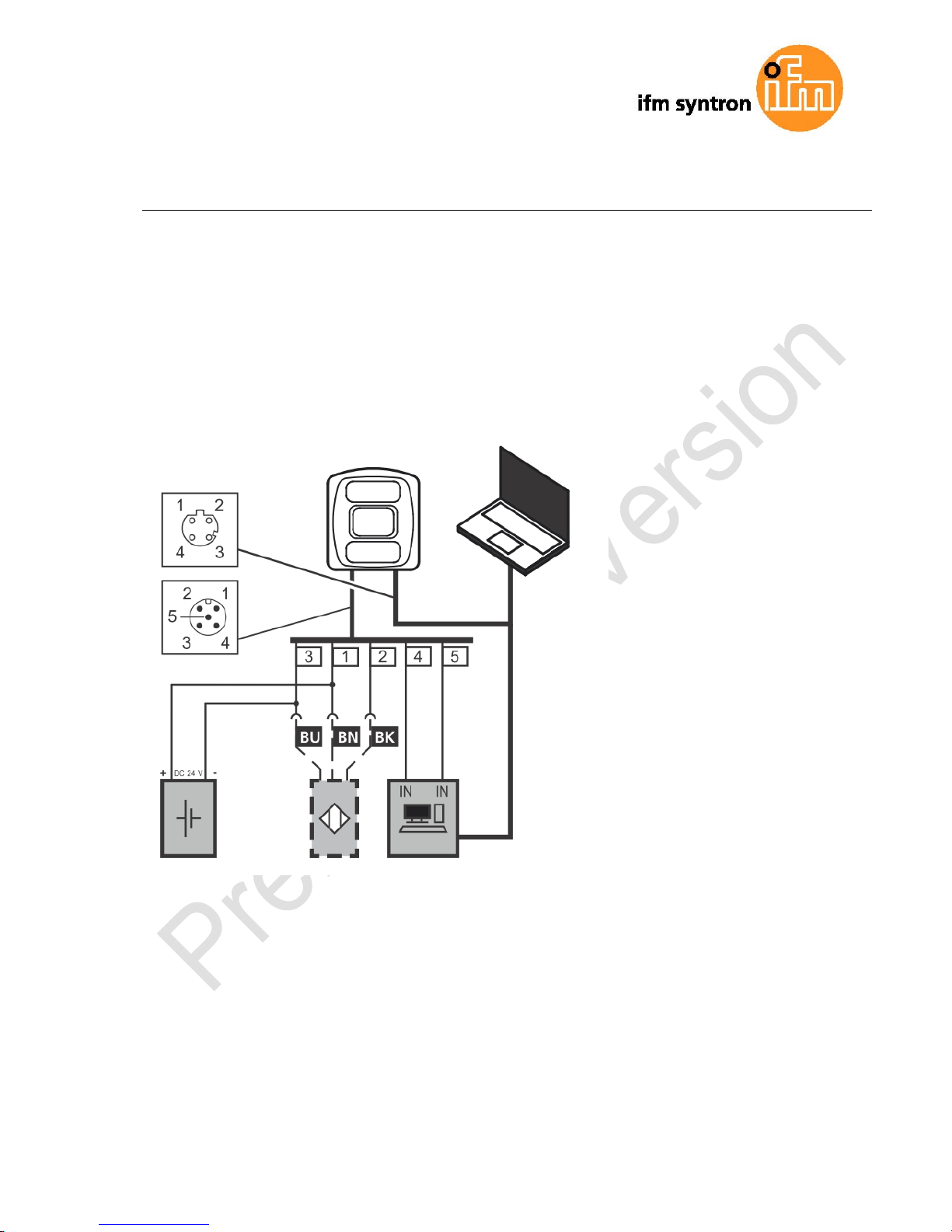
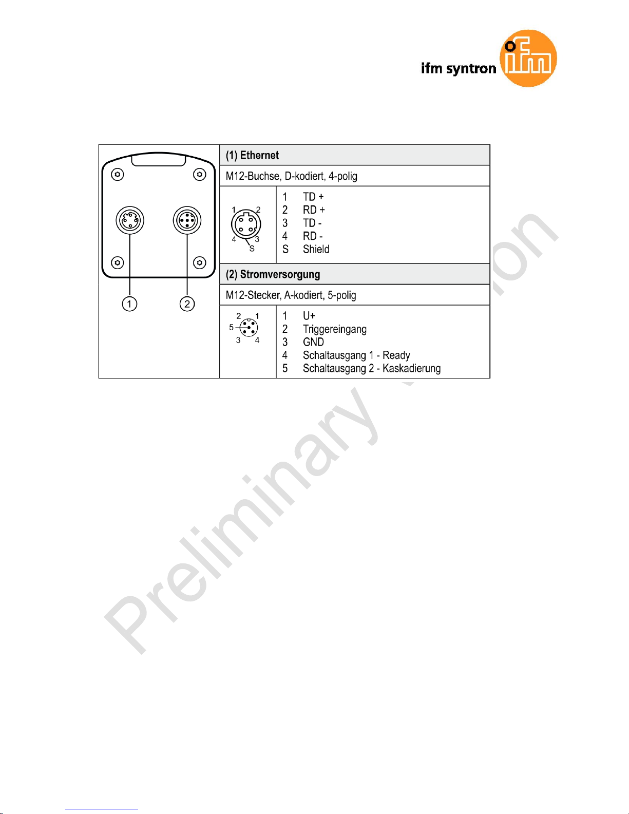
6 ELECTRICAL CONNECTION
ATTENTION
The unit must be connected by a qualified electrician.
Device of protection class III (PC III)
Electric supply via PELV circuits only.
Electric supply must comply with UL61010-1, chap. 9.4 - Limited Energy.
The separation of external circuits must comply with UL61010-2-201, fig. 102.
► Disconnect power before connecting the unit.
Page 10
Seite 10 von 72
6.1 Wiring
Page 11

Seite 11 von 72
7 XML-RPC INTERFACE
In case the camera O3D3xx should not be configured by the “ifmVisionAssistant”, the XMLRPC interface can be used instead.
Note: general information about XML-RPC is found on the website
http://xmlrpc.scripting.com/spec
To send a command over the XML-RPC interface the command has to be on a special layout. In this command, linefeeds and carriage returns are essential.
Several commands will use different URL in the XML-RPC header.
7.1 Sample XML-RPC command
All following XML-RPC commands will have this type of layout:
POST /RPC3 HTTP/1.0User-Agent: Frontier/5.1.2 (WinNT)
Host: betty.userland.com
Content-Type: text/xml
Content-length: 181
<?xml version="1.0"?>
<methodCall>
<methodName>examples.getStateName</methodName>
<params>
<param>
<value><i4>41</i4></value>
</param>
</params>
</methodCall
Page 12

Seite 12 von 72
Following example contains one command of the O3D3xx:
POST /api/rpc/v1/com.ifm.efector/
User-Agent: Frontier/5.1.2 (WinNT)
Host: 192.168.0.69
Content-Type: text/xml
Content-length: 94
<?xml version="1.0"?>
<methodCall>
<methodName>getParameter</methodName>
</methodCall>
7.2 XML-RPC Objects
To communicate and to configure the device over XML-RPC the XML-RPC commands have
to use different XML-RPC Objects. Different commands need different XML-RPC Objects
(see XML-RPC command references).
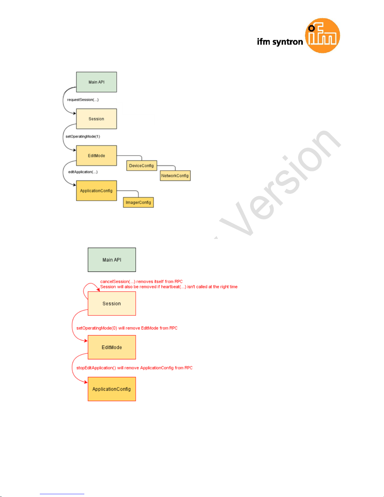
The Interface of O3D3xx is structured in an object-oriented way. Some of the objects are
available all the time, others are only available after bringing the device into a special
mode by calling a method on an already available object. This mechanism is used to model
system-requirements (e.g. password-protection)
Note: It could be necessary to send heartbeats so that there will be no session-timeout.
The following diagram should give an overview how objects are related to each other and
which methods must be called to make others available:
Page 13
Seite 13 von 72
Page 14

Seite 14 von 72
7.2.1 Main-Object:
Object-URI: /api/rpc/v1/com.ifm.efector/
This is the main-object of RPC, it allows to access some basic information and contains
methods for activating edit-mode. Most of its methods are only Getter, because it should be
possible to lock the editing behind a password.
7.2.2 SessionObject
Object-URI e.g.: /api/rpc/v1/com.ifm.efector/session_d21c80db5bc1069932fbb9a3bd841d0b/
The URL Part “d21c80db5bc1069932fbb9a3bd841d0b” is a sample. If the command "requestSession" from the Main-Object is used without a parameter the C3 sample will generate one and sent this back. It is also possible to define a “Session-Object” by own when it
is used as the parameter of “requestSession”.
7.2.3 EditMode-Object
Object-URI e.g.: /api/rpc/v1/com.ifm.efector/session_d21c80db5bc1069932fbb9a3bd841d0b/edit/
This object is only available if the device is in edit-OperatingMode. Index of Applications
must be between 1 and 32. The device must only support 32 applications and the indexes
must start at 1.
7.2.4 DeviceConfig-Object
Object-URI e.g.:
/api/rpc/v1/com.ifm.efector/session_d21c80db5bc1069932fbb9a3bd841d0b/edit/device/
7.2.5 Device/NetworkConfig-Object
Object-URI e.g.:
/api/rpc/v1/com.ifm.efector/session_d21c80db5bc1069932fbb9a3bd841d0b/edit/device/network/
7.2.6 ApplicationConfig-Object (editable application)
Object-URI e.g.:
/api/rpc/v1/com.ifm.efector/session_d21c80db5bc1069932fbb9a3bd841d0b/edit/application/
Page 15

Seite 15 von 72
7.2.7 App./ImagerConfig-Object (O3D3xx)
Object-URI e.g.:
/api/rpc/v1/com.ifm.efector/session_d21c80db5bc1069932fbb9a3bd841d0b/edit/application/i
mager_001/
As there is only one imger-config on O3D3xx, the ID must be fixed to "001". Data of this
object is persistent saved, when calling "save" on ApplicationConfig-object. The imager
config RPC-object has multiple sub-types. Only parameters relevant for a specific type are
available while it is active. They are based on frequency (extending the distance) and integration-intervals (extending the measure-details).
type-names, based on GUI-draft (under 5 meter->single Frequency, upto30 meter->double
Freq., more than 30 Meter -> 3Freq.):
under5m_low
under5m_moderate
under5m_high
upto30m_low
upto30m_moderate
upto30m_high
morethan30m_low
morethan30m_moderate
morethan30m_highunder5m_high
7.2.8 Image-Settings Filt er-Parameter
There must be a RPC-object for spatial filter parameters in each imager configuration.
Object-URI e.g.:
/api/rpc/v1/com.ifm.efector/session_d21c80db5bc1069932fbb9a3bd841d0b/edit/application/imager_001/spatialfi
lter
There must be a RPC-object for temporal filter parameters in each imager configuration.
Object-URI e.g.:
/api/rpc/v1/com.ifm.efector/session_d21c80db5bc1069932fbb9a3bd841d0b/edit/application/imager_001/tempor
alfilter
Data of these objects are persistent saved, when calling "save" on ApplicationConfig-object.
Page 16

Seite 16 von 72
8 PROCESS INTERFACE
The process interface is used during the normal operation mode for to get operational data
(e.g. 3D-images, process values) from the O3D3xx.
8.1 Sending commands
For sending commands over the process interface, the commands have to be send with a
special protocol and as strings. This protocol conforms to the version 3 of the O2V/O2D
products.
Structure of the protocol:
<Ticket><length>CR LF <Ticket><contents>CR LF
Abbreviation Description ASCII code (dec)
CR Carriage Return
13
LF Linefeed
10
< > Marking of a placeholder (e.g.
<code> is a placeholder for
code)
[ ]
Optional argument (possible
but not required)
<contents> is the command to the device (e.g. trigger the unit).
<ticket> is a character string of 4 digits 0-9, to be interpreted as decimal
number. If a message with a specific ticket is sent to the device, its
reply will contain the same ticket
<length> is a character string beginning with the letter 'L' followed by 9 digits
to be interpreted as decimal number. This figure indicates the length
of the following data (<ticket><contents>CR LF) in bytes.
Page 17

Seite 17 von 72
Version
input format output format
V1 <Content>CR LF as input
V2 <Ticket><Content>CR LF as input
V3 <Ticket><Length>CR+LF<Ticket><Content>CR
LF
as input
V4 <Content>CR LF <length>CR
LF<Content>CR LF
The default protocolversion is „V3“.
Page 18

Seite 18 von 72
8.2 Receiving images
For receiving the image data there has to be a TCP/IP socket communication established.
This communication works on the Port 50010. After opening the socket communication the
O3D3XX sample will automatically (if the unit is in free run mode) send the image data
through this socket to the TCP/IP client (PC).
PCIC output per frame. The following data shall be submitted in this sequence:
Component Content
Ticket and length information Please see chapter 8.2
Ticket „0000“
Start sequence String "star" (4 bytes)
normalized amplitude image
output format: 16 Bit Unsigned Integer.
1 image
distance image
output format: 16 Bit Unsigned Integer. Unit is
mm.
1 image
x-image
output format: 16 Bit Signed Integer. Unit ist mm.
1 image
y-image
output format: 16 Bit Signed Integer. Unit ist mm.
1 image
z-image
output format: 16 Bit Signed Integer. Unit ist mm.
1 image
Confidence image
output format: 8 Bit Unsigned Integer
1 image
Diagnostic data
Stop sequence String "stop" (4 bytes)
Ticket finish <CR><LF>
Page 19

Seite 19 von 72
Diagnostic data output has the following structure:
Illumination Temperature
32-bit signed int 4 bytes
Frontend Temperature 1
32-bit signed int 4 bytes
Frontend Temperature 2
32-bit signed int 4 bytes
i.mx6 Temperature 32-bit signed int 4 bytes
Frametime (planned) 32-bit unsigned
integer
4 bytes
Framerate 32-bit unsigned
integer
4 bytes
All temperature values have the unit 0.1 °C, invalid temperatures have the value 0x7FFF
(32767).
i.mx6 temperature is not measured in C3 sample. Therefor these temperatures have the
value 0x7FFF (32767).
Page 20

Seite 20 von 72
8.3 Image data
For every image there will be a separate chunk. The chunk is a part of the response frame
data from the process interface. The image data layout of the response is separated to
these points:
The header of each chunk contains different kind of information. This information is separated into Bytes. The information contains e.g. the kind of image which will be in the “PIXEL_DATA” and the size of the chunk.
Chunk type:
Offset Name Description Size
[Byte]
0x0000 CHUNK_TYPE
Defines the type of the chunk. For each
distinct chunk type a own type has to be
defined.
4
0x0004 CHUNK_SIZE
Size of the whole image chunck in bytes.
After this count of bytes the next chunk
starts.
4
0x0008 HEADER_SIZE
Number of bytes starting from 0x0000 until
PIXEL_DATA
4
0x000C HEADER_VERSION Version number of the header 4
0x0010 IMAGE_WIDTH Image width in pixel 4
Header
Image data
Chunk
Page 21

Seite 21 von 72
0x0014 IMAGE_HEIGTH Image height in pixel 4
0x0018 PIXEL_FORMAT Pixel-Format 4
0x001C TIME_STAMP Timestamp in uS 4
0x0020 FRAME_COUNT Frame count according to algorithm output 4
0x0024 PIXEL_DATA
The pixel data in the given type and dimension
of the image.
Padded to 4-Byte boundary.
Page 22

Seite 22 von 72
Available Chun types
Constant Value Description
USERDATA 0 undefined userdata with arbritrary content
RADIAL_DISTANCE_IMAGE 100
Each pixel of the distance matrix denotes the
ToF distance measured by the corresponding
pixel or group of pixels of the imager. The distance value is corrected by the camera's calibration, excluding effects caused by multipath
and multiple objects contributions (e.g. "flying
pixels"). Reference point is the optical center
of the camera inside the camera housing.
Invalid PMD pixels (e.g. due to saturation)
have a value of zero.
Data type: 16 bit unsigned integer (little endian)
Unit: millimetres
NORM_AMPLITUDE_IMAGE 101
Each pixel of the amplitude matrix denotes the
amount of modulated light (ie the light from the
camera's active illumination) which is reflected
by the appropriate object. Higher values indicate higher PMD signal strengths and thus a
lower amount of noise on the corresponding
distance measurements. The amplitude value
is directly derived from the PMD phase measurements without normalization to exposure
time. In double exposure mode, the lack of
normalization may lead (depending on the
choosen exposure times) to inhomogeneous
amplitude image impression, if the a certain
pixel is taken from the short exposure time and
some of its neighbors are not.
Invalid PMD pixels (e.g. due to saturation)
have an amplitude value of 0.
By the algorithm a float32 normalized Amplitude image is created. Its values range from
94.3 to 0.005, given the current (C3 sample)
minimal and maximal amplitude settings. To
have some room for improvement the scaling
should be done as follows:
Normalized Amplitude Image 16 Bit: IPUint16
Normalized Amplitude Image from algorithm :
IPfloat32
Conversion: IPUint16 = round(65535/100 *
Page 23

Seite 23 von 72
IPfloat32)
If a value larger (smaller) than 100 (0) the
converted value is to be set to 65535 (0).
Data type: 16 bit unsigned integer
AMPLITUDE_IMAGE 103
Each pixel of the amplitude matrix denotes the
amount of modulated light (ie the light from the
camera's active illumination) which is reflected
by the appropriate object. Higher values indicate higher PMD signal strengths and thus a
lower amount of noise on the corresponding
distance measurements. The amplitude value
is directly derived from the PMD phase measurements without normalization to exposure
time. In double exposure mode, the lack of
normalization may lead (depending on the
choosen exposure times) to inhomogeneous
amplitude image impression, if the a certain
pixel is taken from the short exposure time and
some of its neighbors are not.
Invalid PMD pixels (e.g. due to saturation)
have an amplitude value of 0.
CARTESIAN_X_COMPONENT 200
The X matrix denotes the X-component of the
cartesian coordinate of a PMD 3D measurement. The origin of the camera's coordinate
system is in the middle of the lens' front glass,
if the extrinsic parameters are all set to 0. Data type: 16 bit signed integer
Unit: millimetres
CARTESIAN_Y_COMPONENT 201
The Y matrix denotes the Y-component of the
cartesian coordinate of a PMD 3D measurement. The origin of the camera's coordinate
system is in the middle of the lens' front glass,
if the extrinsic parameters are all set to 0. Data type: 16 bit signed integer
Unit: millimetres
CARTESIAN_Z_COMPONENT 202
The Z matrix denotes the Z-component of the
cartesian coordinate of a PMD 3D measurement. The origin of the camera's coordinate
system is in the middle of the lens' front glass,
if the extrinsic parameters are all set to 0. Data type: 16 bit signed integer
Unit: millimetres
Page 24

Seite 24 von 72
CARTESIAN_ALL 203
CARTESIAN_X_COMPONENT, CARTESIAN_Y_COMPONENT, CARTESIAN_Z_COMPONENT
UNIT_VECTOR_ALL 223
The unit vector matrix contains 3 values [ex,
ey, ez] for each PMD pixel, ie the data layout
is [ex_1,ey_1,ez_1, ... ex_N, ey_N, ez_N],
where N is the number of PMD pixels. Multiplying a PMD distance measurement by the appropriate component leads to the corresponding cartesian coordinate: [X_i, Y_i, Z_i] = D_i *
[ex_i, ey_i ez_i].
Data type: 16 bit signed integer
CONFIDENCE_IMAGE 300 See 8.4 Additional information for image data
DIAGNOSTIC 302 See 8.2 Receiving images
Pixel format:
Constant
V
alue Description
FORMAT_8U
0
8bit unsigned integer
FORMAT_8S
1
8bit signed integer
FORMAT_16U
2
16bit unsigned integer
FORMAT_16S
3
16bit signed integer
FORMAT_32U
4
32bit unsigned integer
FORMAT_32S
5
32bit signed integer
FORMAT_32F
6
32bit floating point number
FORMAT_64U
7
64bit unsigned integer
FORMAT_64F
8 64bit floating point number
Page 25

Seite 25 von 72
8.4 Additional information for image data
Further information for the Confidence image
Bit Value Description
0 1 = pixel invalid
Pixel invalid (NV)
The pixel is invalid. To determine,
whether a pixel is valid or not only
this bit needs to be checked. For a
reason why the bit is invalid the other confidence bits may be checked.
1 1 = pixel saturated
Pixel is saturated (SA)
Contributes to pixel validity: yes
2 1 = bad A-B symmetry
A
-B pixel symmetry (SY)
The A-B symmetry value of the four
phase measurements is above
threshold.
Remark: This symmetry value is used
to detect motion artefacts. Noise
(e.g. due to strong ambient light or
very short integration times) or PMD
interference may also contribute.
Contributes to pixel validity: yes
3 1 = amplitude below minimum
amplitude threshold
A
mplitude limits (AM)
The amplitude value is below minimum amplitude threshold.
Contributes to pixel validity: yes
4+5 Bit 5, Bit 4
0 0 unused
0 1 shortest exposure
time (only used in 3 exposure
mode)
1 0 middle exposure
time in 3 exposure mode, short
exposure in double exposure
mode
1 1 longest exposure
time (always 1 in single exposure
mode)
Exposure time indicator
The two bits indicate, which exposure
time was used in a multiple exposure
measurement.
Contributes to pixel validity: no
6 1= motion artefact compensated
Not implemented
7 1 = pixel suspect/defect
Suspect pixel (SU)
This pixel has been marked as "sus-
Page 26

Seite 26 von 72
pect" or "defect" and values have
been replaced by interpolated values
from the surrounding.
Contributes to pixel validity: no
Page 27

Seite 27 von 72
8.5 Configuration of PCIC output
The user has the possibility to define his own PCIC output. This configuration is only valid
for the current PCIC connection. It does not affect any other connection and will lost after
disconnecting.
For configuring the PCIC output a “flexible”.layouter concept is used, represented by a
JSON string. The format of the default configuration is as follows:
{
"layouter": "flexible",
"format": { "dataencoding": "ascii" },
"elements": [
{ "type": "string", "value": "star", "id": "start_string" },
{ "type": "blob", "id": "normalized_amplitude_image" },
{ "type": "blob", "id": "x_image" },
{ "type": "blob", "id": "y_image" },
{ "type": "blob", "id": "z_image" },
{ "type": "blob", "id": "confidence_image" },
{ "type": "blob", "id": "diagnostic_data" },
{ "type": "string", "value": "stop", "id": "end_string" }
]
}
This string can be retrieved by the C? command, altered and sent back using the c com-
mand.
The layouter has the following main object properties:
Name Description Details
layoute
r
Defines the basic data output format.
So far only “flexible” is supported
type: string
format
Defining format details, the definitions in the main-object are the defaults
for any following data-elements (e.g. if it says dataencoding=binary, all
data-elements should be binary encoded instead of ASCII).
type: object
elements
List of data-elements which should be written. type: array of objects
Page 28

Seite 28 von 72
The actual data is defined within the “elements” properties and may consist of these settings:
Name Description Details
type
Defines the type of data which should be written.
The data might be stored in a different type (e.g. stored
as integer but should be output as float32)
The type "records" will need some special handling..
type: string
id
Defines an identifier for this data-element.
If there is no fixed value (property "value"), the data
should be retrieved via id.
type: string
value
Optional property for defining a fixed output value. type: any JSON
value
format
Type depending option for fine tuning the output format.
e.g. cut an integer to less than 4 bytes
type object
Available values for the type propertie
Type Description
records
Defines that this element represents a list of records.
If type is set to "records", there must be a "elements" property.
The "elements" property defines which data should be written per record.
string
Data is written as string.
Most of the time this will be used with "value"-property to write fixed start-,
end- or delimiter-text.
Text-Encoding should be UTF8, if there is nothing else specified by formatproperties.
float32
Data is written as floating point number.
This has a lot of formatting options (at least with "flexible"-layouter)
See chapter about format-properties (
660606-6621 - Number Format
Properties
).
uint32
Data is written as integer.
This has a lot of formatting options (at least with "flexible"-layouter)
See chapter about format-properties (
660606-6621 - Number Format
Properties
).
int32
Data is written as integer.
This has a lot of formatting options (at least with "flexible"-layouter)
See chapter about format-properties (
660606-6621 - Number Format
Properties
).
Page 29

Seite 29 von 72
uint16
limits the output to two byte in binary-encoding, beside the binary limitation it
acts like uint32
int16
limits the output to two byte in binary-encoding, beside the binary limitation it
acts like int32
uint8
limits the output to one byte in binary-encoding, beside the binary limitation it
acts like uint32
int8
limits the output to one byte in binary-encoding, beside the binary limitation it
acts like int32
blob
Data is written as a blob (byte by byte like it came from data-provider).
( Binary Large Object )
Depending on the desired data format the user may tune his output data with further “format” properties
Common format properties
FormatProperties
Allowed values Default
dataencoding "ascii" or "binary"
can be defined in top-level-object and overwritten on element-objects.
"ascii"
scale "float value with decimal separator '.'" to scale the results for output byte
width
1.0
offset "float value with decimal separator '.'" 0.0
Binary format properties
FormatProperties
Allowed values Default
order little,big and network little
Page 30

Seite 30 von 72
ASCII format properites:
Format-Properties Allowed values Default
width output width. If the resulting value exceeds the
width field the the result will not be turncated
0
fill fill character " "
precision Precision is the number of digits behind the
decimalseparator.
6
displayformat fixed,scientific fixed
alignment left,right right
decimalseparator 7-bit characters for e.g. "." "."
base Defines if the output should be:
binary (2)
octal (8)
decimal (10)
hexadecimal (16)
10
Example of a format configuration of the temperature (id:
temp_illu) element.
1. Illu Temperature like this "33,5___":
c000000226{ "layouter": "flexible", "format": { "dataencoding": "ascii" }, "elements": [ { "type":
"float32", "id": "temp_illu", "format": { "width": 7, "precision": 1, "fill": "_", "alignment":
"left", "decimalseparator": "," } } ] }
2. Illu Temperature as binary (16bit integer, 1/10 °C):
c000000194{ "layouter": "flexible", "format": { "dataencoding": "ascii" }, "elements": [ { "type":
"int16", "id": "temp_illu", "format": { "dataencoding": "binary", "order": "network", "scale": 10 } } ] }
3. Illu Temperature in °F (e.g. "92.3 Fahrenheit" ):
c000000227{ "layouter": "flexible", "format": { "dataencoding": "ascii" }, "elements": [ { "type":
"float32", "id": "temp_illu", "format": { "precision": 1, "scale": 1.8, "offset": 32 } }, { "type": "string",
"value": " Fahrenheit" } ] }
Page 31

Seite 31 von 72
The following element ids are available:
ID Description Native Datatype
evaltime
evaluation time for current frame in milliseconds unsigned int
32Bit
framerate Current framerate in Hz float32
temp_front1
Temperature measured in the device while capturing this result.
Measured by first sensor on imager board.
float32, °C
--> SYRS: "Einheit: °C"
temp_front2
Temperature measured in the device while capturing this result.
Measured by second sensor on imager board.
float32, °C
temp_imx6
Temperature measured in the device while capturing this result.
Measured inside the main CPU.
float32, °C
temp_illu
Temperature measured in the device while capturing this result.
Measured on the illumination board.
float32, °C
extrinsic_calibration
Extrinsic Calibration Values
amplitude_image
normalized_amplitude_image
Amplitude/Intensity image, there are multiple
variants of them.
distance_image
Radial distance image.
x_image
y_image
z_image
Cartesian coordinates for each pixel.
Each dimension is a separat image.
all_cartesian_vector_matrices
Combination of all cartesian images (x+y+z)
confidence_image
Image with a flag-variable per pixel.
all_unit_vector_matrices
Image containing a unit-vector per pixel.
For converting radial distance values into x-/y/z-values.
Page 32

Seite 32 von 72
8.6 Sample C++ Code for setting up a socket
//Including the winsocket library for creating sockets later in the code
#include <winsock.h>
#pragma comment(lib, "ws2_32.lib")
void main(void)
{
//Start the winsocket
WSADATA wsadata;
WSAStartup(MAKEWORD(2,2),&wsadata);
//Set up the socket
SOCKET s;
s = socket(AF_INET, SOCK_STREAM, 0);
SOCKADDR_IN target; //Inside target will the socket address information be saved
target.sin_family = AF_INET; //address family is Internet, over which we will
communicate
target.sin_port = htons(50010); //IT is the Portnumber from the C3 Sample for the
PCIC
target.sin_addr.s_addr = inet_addr("192.168.0.69"); //Ip address of the C3 Sample
//Definde the socket and connect it to the C3Sample
s = socket(AF_INET, SOCK_STREAM, IPPROTO_TCP);
connect(s, (SOCKADDR *)&target, sizeof(target));
//Disconnect the socket
closesocket(s);
WSACleanup();
}
Page 33

Seite 33 von 72
9 XML-RPC COMMAND REFERENCES
9.1 "setParameter" must be implemented on all RPC-objects
which offer parameter
Method Name
setParameter
Description
Sets a parameter to a specific value.
Input Parameters
1. name of parameter :string
2. new value :string
Output Parameters
1. empty-string (compatibility for classic XmlRPC-Client)
9.2 Main-Object
9.2.1 "getParameter”
Method Name
getParameter
Description
Getter for the device-global parameters
Input Parameters
Name of a device-parameter :string
Output Parameters
Value of the requested parameter :string
9.2.2 "getAllParameters"
Method Name
getAllParameters
Description
Getter for the parameters described here:
This is an additional getter outside of Edit-Sessions, so it is possible to
read device informations without login.
Input Parameters
none
Output Parameters
1. Struct (name contains parameter-name, value the stringified parametervalue)
Page 34

Seite 34 von 72
9.2.3 "getSWVersion"
Method Name
getSWVersion
Description
Returns version-information of all software componenents
Input Parameters
none
Output Parameters
1. Struct of strings ( e.g. { "IFM_Software": "0.01.07", "Frontend":
"01.05.02", ... } )
*mandatory keys:
"IFM_Software"
"Linux"
"Main_Application"
"Diagnostic_Controller"
"Algorithm_Version"
"Calibration_Version"
"Calibration_Device"
Page 35

Seite 35 von 72
9.2.4 "getHWInfo"
Method Name
getHWInfo
Description
Returns hardware-information of all components
Input Parameters
none
Output Parameters
Struct of strings ( e.g. { "MACAddress":
"00:02:01:40:06:C9", "Frontend": "#!01_F340_001_...", ... } )
*mandatory keys:
"MACAddress"
"Connector"
"Diagnose"
"Frontend"
"Illumination"
"Mainboard"
9.2.5 "getApplicationList”
Method Name
getApplicationList
Description
Delivers basic information of all Application stored on the device.
This should be available before password-session, so the CombiGUI
could display Sensor-screen before login.
Input Parameters
none
Output Parameters
1. Array of structs (Index: int, Id: int, Name: string, Description: string)
Page 36

Seite 36 von 72
9.2.6 "requestSession"
Method Name
requestSession
Description
Request a session-object for access to the configuration and for
changing device operating-mode.
This should block parallel editing and allows to put editing behind
password.
The ID could optionally be defined from the external system, but it
must be the defined format (32char "hex").
If it is called with only one parameter, the device will generate a SessionID.
The session will start with a default timeout("SessionTimeout" deviceparameter), the timeout can be extended by calling "heartbeat".
The device will stay in RUN-mode.
If password is disabled on the device, the value given as passwordparameter is ignored.
Input Parameters
1. Password: string
2. SessionID: string (optional)
Output Parameters
1. SessionID: string
9.2.7 "reboot"
Method Name
reboot
Description
Reboot system, parameter defines which mode/system will be booted
Input Parameters
1. type of system that should be booted after shutdown :int
0: productive-mode
1: recovery-mode
Output Parameters
1. empty-string (compatibility for classic XmlRPC-Client)
9.2.8 "systemCommand”
Method Name
systemCommand
Description
Performs a generic command on the device.
Input Parameters
1. Command :string
2. Parameter :string
Output Parameters
1. Output :string
Page 37

Seite 37 von 72
9.3 Session-Object
9.3.1 "heartbeat"
Method Name
heartbeat
Description
Extend the live time of edit-session
If the given value is outside the range of "
SessionTimeout", the saved default
timeout will be used.
Input Parameters
1. requested timeout-interval till next heartbeat, in seconds :int
Output Parameters
1. the used timeout-interval, in seconds :int
9.3.2 "cancelSession”
Method Name
cancelSession
Description
Explicit stopping this session
If an application is still in edit-mode, it will implicit do the same as "stopEditingApplication".
Input Parameters
none
Output Parameters
1. empty-string (compatibility for classic XmlRPC-Client)
9.3.3 "exportConfig”
Method Name
exportConfig
Description
exports the whole configuration of the sensor-device
Input Parameters
none
Output Parameters
1. configuration as one data-blob :binary/base64
Page 38

Seite 38 von 72
9.3.4 "importConfi g”
Method Name
importConfig
Description
import whole configuration, with the option to skip specific parts
Input Parameters
1. configuration as one data-blob :binary/base64
2. flags which parts should be loaded:
0x0001: Include Globale-Configuration (Name, Description, Location, ...)
0x0002: Include Network-Configuration (IP, DHCP, ...)
0x0010: Include All Application-Configurations
Output Parameters
1. empty-string (compatibility for classic XmlRPC-Client)
9.3.5 "exportApplication”
Method Name
exportApplication
Description
exports one application-config
Input Parameters
1. Application Index
Output Parameters
1. application-config as one data-blob :binary/base64
9.3.6 "importApplic ation”
Method Name
importApplication
Description
imports an application-config and creates a new application with it.
The name of the application should be based on the one stored in the exported-config.
If the name should be unique, the sensor must generate an suffix in case of
a naming conflict.
The device will give a new ID, if there is an ID inside the config-data it
must be ignored.
The device will put the new application on the first free Index.
Input Parameters
1. application-config as one-data-blob: binary/base64
Output Parameters
1. Index of new application
Page 39

Seite 39 von 72
9.3.7 "setOperatingMode"
Method Name
setOperatingMode
Description
Changes the operation mode of the device.
Setting this to "edit" will enable the "EditMode"-object on RPC.
Input Parameters
1. mode :int
0: run mode
1: edit mode
Output Parameters
1. empty-string (compatibility for classic XmlRPC-Client)
Page 40

Seite 40 von 72
9.4 EditMode-Object
9.4.1 "factoryReset"
Method Name
factoryReset
Description
sets all configurations back to "werkseinstellungen"
Input Parameters
none
Output Parameters
1. empty-string (compatibility for classic XmlRPC-Client)
Note: A factory reset will delete all app lications which are saved on the camera.
9.4.2 "editApplication"
Method Name
editApplication
Description
Puts a specified Application into edit-status.
This will attach an application-object to the RPC interface.
The name of the object will be application independent.
This does not change the "ActiveApplication"-parameter.
Input Parameters
1. Application index :int
Output Parameters
1. empty-string (compatibility for classic XmlRPC-Client)
9.4.3 "stopEditingApplication"
Method Name
stopEditingApplication
Description
Tells the device that editing this application was finished.
Unsaved changed should be discard.
HINT: The device must also call this implicit, when a edit-session timed out
or was closed by "cancelSession".
Input Parameters
none
Output Parameters
1. empty-string (compatibility for classic XmlRPC-Client)
Page 41

Seite 41 von 72
9.4.4 "createApplicati on"
Method Name
createApplication
Description
Creates an "empty" application. The embedded side should initialize all
needed parameters and structures.
Such an application might be in an non-activatable state,
this means it could be saved on the device, but not set as active application.
Input Parameters
none
Output Parameters
1. Index of new application :int
9.4.5 "copyApplication"
Method Name
copyApplication
Description
Creates a new application by copying the configuration of another application.
The device will generate an ID for the new application and put it on a free
Index.
Input Parameters
1. Index of the application which should be copied :int
Output Parameters
1. Index of new application :int
9.4.6 "deleteApplication"
Method Name
deleteApplication
Description
Deletes the application form sensor
If the deleted application was the active one, the sensor will have no active
application anymore until the user picks one. (O2V-behavior)
Input Parameters
1. Index of application :int
Output Parameters
1. empty-string (compatibility for classic XmlRPC-Client)
"changeNameAndDescription" changeNameAndDescription
Page 42

Seite 42 von 72
Method Name
Description
Input Parameters
1. Application index :int
2. new name of the application: string(utf8, max. 64 character)
3. new description of the application: string(utf8, max. 500
character)
Output Parameters
1. empty-string (compatibility for classic XmlRPC-Client)
9.4.7 "moveApplications"
Method Name
moveApplications
Description
Moves applications to other Index.
There must be all applications in the new list, none of them duplicated and
no Index used twice.
The ID is a fixed value that stays the same as long as the application stays
on the sensor.
The Index could be changed and is used to address the application via
PCIC, XML-RPC and Digital-IO.
Input Parameters
1. Array of structs (Id :int, Index :int)
Output Parameters
1. empty-string (compatibility for classic XmlRPC-Client)
Page 43

Seite 43 von 72
9.5 DeviceConfig-Object
9.5.1 "activatePassword"
Method Name
activatePassword
Description
Set a password and activate it for the next edit-session.
Making this change presistant requires to call "save" on the DeviceConfig.
Input Parameters
1. Password :string
Output Parameters
1. empty-string (compatibility for classic XmlRPC-Client)
9.5.2 "disablePassword"
Method Name
disablePassword
Description
Disables the password-protection.
Making this change presistant requires to call "save" on the DeviceConfig.
Input Parameters
none
Output Parameters
1. empty-string (compatibility for classic XmlRPC-Client)
9.5.3 "save"
Method Name
save
Description
Store current configuration in persistent memory.
If this is not called after changing device-parameters (via setParameter),
changes will get lost on reboot.
Input Parameters
none
Output Parameters
1. empty-string (compatibility for classic XmlRPC-Client)
Page 44

Seite 44 von 72
9.5.4 Parameters
Parameters of DeviceConfig
Methods for parameter access are defined here:
Parameter Name Data
Type
Description
Name string
(utf8)
User defined name of the device. (max. 64 characters)
Description string
(utf8)
User defined description of the device. (max. 500 characters)
ActiveApplication int
*has
limits
Index of active Application
This effects only RUN-mode:
* defines the application active on startup (if staticapplication-switching is disabled)
* contains the current active application (could also be
changed via PCIC-command)
* 0 means there is no application active (see SYRS 6606063530 )
PcicTcpPort int TCP/IP-Port for PCIC-connections.
PcicProtocolVersion int
*has
limits
Sub Protocol of PCIC, see specification of PCIC:
IOLogicType int
*has
limits
Defines logic-type of all digital-pins.
Allowed values:
0: NPN
1: PNP
IODebouncing bool Applies to all inputs
IOExternApplicationSwitch int
*has
limits
Allowed values:
0: off
1: static via I/O
2: pulse driven via I/O
3: pulse driven via trigger
SessionTimeout int
*has
limits
number of seconds which a session stays before a call to
"heartbeat"-method is needed
ExtrinsicCalibTransX double Extrinsic calibration, Transition in X direction
ExtrinsicCalibTransY double Extrinsic calibration, Transition in Y direction
Page 45

Seite 45 von 72
ExtrinsicCalibTransZ double Extrinsic calibration, Transition in Z direction
ExtrinsicCalibRotX double Extrinsic calibration, Rotation around X-axis
ExtrinsicCalibRotY double Extrinsic calibration, Rotation around Y-axis
ExtrinsicCalibRotZ double Extrinsic calibration, Rotation around Z-axis
IPAddressConfig int
readonly, The GUI requires to know if the device is on a Discovery-IP-address for multiple usecases. This information was
extended to reflect all kinds of IP-address situations.
Allowed values:
0: static (IP-address explicit defined inside the device)
1: DHCP (using a DHCP-server in the network)
2: LinkLocal (configured to DHCP, but no server which provided an address)
3: Discovery (changed by IP4Discovery mechanism)
PasswordActivated bool
readonly, is true if the password-protection is enabled
OperatingMode int
readonly, mode of device (RUN, EDIT)
see "setOperatingMode" (the setter is outside of edit-mode,
but inside of session)
DeviceType string
readonly, Delivers a type description, unique by imager, evaluation-logic and device-interface
Format could be like this: "[VendorID]:[TypeID]"
e.g. "1:42"
ArticleNumber string
readonly, Official catalog-number
ArticleStatus string
readonly, Official two-letter status code
UpTime double
readonly, Hours since last reboot
ImageTimestampReference int
readonly, The image-data contains a timestamp (32bit int, µs)
This should return the current timestamp as a reference to the
images received.
TemperatureFront1 double
readonly, Temperature measured in the device, value is in
degree Celsius.
Measured by first sensor on imager board.
TemperatureFront2 double
readonly, Temperature measured in the device, value is in
degree Celsius.
Measured by second sensor on imager board.
TemperatureIMX6 double
readonly, Temperature measured in the device, value is in
Page 46

Seite 46 von 72
degree Celsius.
Measured inside the main CPU.
TemperatureIllu double
readonly, Temperature measured in the device, value is in
degree Celsius.
Measured on the illumination board.
*has limits: parameters with this marker are listed in the reply of getAllParameterLimits-
method
Default values of DeviceConfig parameters
The default values of the device configuration parameters are:
Parameter Name Data
Type
Default Value
Name string
(utf8)
"New sensor"
Description string
(utf8)
""
ActiveApplication int 0
PcicTcpPort int 50010
PcicProtocolVersion int 3
IOLogicType int 1
IODebouncing bool true
IOExternApplicationSwitch int 0
SessionTimeout int 30
ExtrinsicCalibTransX double 0.0
ExtrinsicCalibTransY double 0.0
ExtrinsicCalibTransZ double 0.0
ExtrinsicCalibRotX double 0.0
ExtrinsicCalibRotY double 0.0
Page 47

Seite 47 von 72
ExtrinsicCalibRotZ double 0.0
IPAddressConfig int 0
PasswordActivated bool false
OperatingMode int 0
For all other DeviceConfig parameters there are no defined default values because they are
either device-dependent (DeviceType, ArticleNumber, ArticleStatus) or volatile (UpTime,
ImageTimestampReference).
Page 48

Seite 48 von 72
Minimum and maximum values of DeviceConfig parameters
The minimum and maximum values of the device configuration parameters are:
Parameter Name Minimum Va-
lue
Maximum Value
ActiveApplication 0 32
PcicProtocolVersion 1 4
IOLogicType 0 1
IOExternApplicationSwitch 0 3 (C3: 0)
SessionTimeout 5 300
Page 49

Seite 49 von 72
9.6 Device/NetworkConfig-Object
9.6.1 "saveAndActivateConfig"
Method Name
saveAndActivateConfig
Description
Reinitialize the network interface so that it uses the configuration which
was set by the other RPC-methods.
There will be no XMLRPC-replay, because the network-interface is instantly
reset.
This must also close the session, as there is no clean way of closing it.
Input Parameters
none
Output Parameters
1. empty-string (compatibility for classic XmlRPC-Client)
9.7 ApplicationConfig-Object
9.7.1 "save"
Method Name
save
Description
stores current configuration in persistent memory.
This should also be possible if the application is not yet in an "activatable"
status.
Input Parameters
none
Output Parameters
1. empty-string (compatibility for classic XmlRPC-Client)
9.7.2 "forceTrigger"
Method Name forceTrigger
Description Do a software-trigger of current active application
Input Parameters
none
Output Parameters
1. empty-string (compatibility for classic XmlRPC-Client)
Page 50

Seite 50 von 72
9.7.3 "validate"
Method Name
validate
Description
Validates the application, this means it checks if the application can
be activated.
HINT: the device should do the same check, while activating an application.
Input Parameters
none
Output Parameters
Array of fault-structs (Id: int, Text: string)
Fault Scenarios
none
Page 51

Seite 51 von 72
9.7.4 Parameters
Parameters of Application
Methods for parameter access are defined here:
Parameter Name Data
Type
Description
Name string
(utf8)
User defined name of the application. (max. 64 characters)
Description string
(utf8)
User defined description of the application. (max. 500 characters)
TriggerMode int
*has
limits
Allowed values:
1: free run
2: process interface
3: positive edge
4: negative edge
5: positive and negative edge
PcicTcpResultOutputEnabled bool Allows to disable the automatic output of results via PCIC.
If it is false, PCIC-commands could be used to access the
data again.
PcicTcpResultSchema string The Schema defines which images and result-data will be
send.
It will also define the order of data-elements and additional
separators.
Contains single-enabling/-disabling of AmplitudeImage, IntensityImage, DistanceImage, XImage, YImage, ZImage, ConfidenceImage, DiagnosticData
*has limits: parameters with this marker are listed in the reply of getAllParameterLimits-
method
Page 52

Seite 52 von 72
Default values of application parameters
The default values of application parameters are:
Parameter Name Data
Type
Default Value
Name string
(utf8)
"New application"
Description string
(utf8)
""
TriggerMode int 1
PcicTcpResultOutputEnabled bool true
PcicTcpResultSchema string ""
Minimum and maximum values of application parameters
The minimum and maximum values of application parameters are:
Parameter Name Minimum Va-
lue
Maximum Value
TriggerMode 1 5 (C3: 2)
Page 53

Seite 53 von 72
9.8 App./ImgagerConfig-Object
9.8.1 "changeType"
Method Name
changeType
Description
Changes the type of imager-configuration.
This changes the set of available parameters and might also change available
RPC-methods.
Input Parameters
1. type :string
Output Parameters
1. empty-string (compatibility for classic XmlRPC-Client)
9.8.2 "availableTypes"
Method Name
availableTypes
Description
Lists all available imager-configuration types.
Input Parameters
none
Output Parameters
1. Array of strings
Page 54

Seite 54 von 72
9.8.3 Parameters
Parameters of all types of Application-ImagerConfig
Methods for parameter access are defined here:
Parameter Name Data Type Description
Type string
readonly, Type of Imager-Configuration, see changeType method
FrameRate double
*has limits
Target frame rate in frames per second for free run mode.
SpatialFilterType int
*has limits
Allowed values:
0: off
1: median filter
2: mean filter
3: bilateral filter
TemporalFilterType
int
*has limits
Allowed values:
0: off
1: temporal mean filter
2: adaptive exponential filter
*has limits: parameters with this marker are listed in the reply of getAllParameterLimits-
method
Default values of common ImagerConfig parameters. The default values of the common imager configuration parameters are:
Parameter Name Data
Type
Default Value
Type string "under5m_low"
FrameRate double 5.0
ReduceMotionArtifacts bool false
SpatialFilterType int 0
AverageFilterNumPictures int 1
Page 55

Seite 55 von 72
Minimum and maximum values of common ImagerConfig parameters
The minimum and maximum values of the common imager configuration parameters are:
Parameter Name Mi nimum
Value
Maximum Value
FrameRate 0.0167 30.0
SpatialFilterType 0 4 (C3: 1)
AverageFilterNumPictures 1 25 (C3: 1)
Parameters only in "under5m_low"-type of Application-ImagerConfig
Parameter Name Data Ty-
pe
Description
ExposureTime int
*has limits
Time for the Exposure
The 2nd ExposureTime will be calculated based on the first one.
ExposureTimeRatio int
*has limits
Ratio of long exposure time to short exposure time.
Channel
int
*has limits
Allowed values:
0: non-group use (like channel1, but additional GUI-option)
1: channel1
2: channel2
3: channel3
Default values of the "under5m_low" mode parameters
Parameter Name Data Ty-
pe
Default Value
ExposureTime int 1000
Channel int 0
Page 56

Seite 56 von 72
Minimum and maximum values of the "under5m_low" mode parameters
Parameter Name Minimum
Value
Maximum Value
ExposureTime 0 10000
Channel 0 3
Parameters only in "under5m_moderate"-type of Application-ImagerConfig
Parameter Name Data Ty-
pe
Description
ExposureTime int
*has limits
Time for the long Exposure
The 2nd ExposureTime will be calculated based on the first one.
Channel
int
*has limits
Allowed values:
0: non-group use (like channel1, but additional GUI-option)
1: channel1
2: channel2
3: channel3
Default values of the "under5m_moderate" mode parameters
Parameter Name Data Ty-
pe
Default Value
ExposureTime int 1000
ExposureTimeRatio int 40
Channel int 0
Page 57

Seite 57 von 72
Minimum and maximum values of the "under5m_moderate" mode parameters
Parameter Name Minimum
Value
Maximum Value
ExposureTime 0 10000
ExposureTimeRatio 2 50
Channel 0 3
Parameters only in "under5m_high"-type of Application-ImagerConfig
Parameter Name Data
Type
Description
Channel int
*has
limits
Allowed values:
0: non-group use (like channel1, but additional GUIoption)
1: channel1
2: channel2
3: channel3
Default values of the "under5m_high" mode parameters
Parameter Name Data
Type
Default Value
Channel int 0
Minimum and maximum values of the "under5m_high" mode parameters
Parameter Name Minimum
Value
Maximum
Value
Channel 0 3
Page 58

Seite 58 von 72
Parameters only in "upto30m_low"-type of Application-ImagerConfig
Parameter Name Data
Type
Description
ExposureTime int
*has
limits
Time for the long Exposure
Channel int
*has
limits
Allowed values:
0: non-group use (like channel1, but additional GUI-option)
1: channel1
2: channel2
3: channel3
Default values of the "upto30m_low" mode parameters
Parameter Name Data
Type
Default Value
ExposureTime int 1000
Channel int 0
Minimum and maximum values of the "upto30m_low" mode parameters
Parameter Name Minimum
Value
Maximum Value
ExposureTime 0 10000
Channel 0 3
Page 59

Seite 59 von 72
Parameters only in "upto30m_moderate"-type of Application-ImagerConfig
Parameter Name Data
Type
Description
ExposureTime int
*has
limits
Time for the long Exposure
The 2nd ExposureTime will be calculated based on the first
one.
ExposureTimeRatio int
*has
limits
Ratio of long exposure time to short exposure time
Channel int
*has
limits
Allowed values:
0: non-group use (like channel1, but additional GUI-option)
1: channel1
2: channel2
3: channel3
Default values of the "upto30m_moderate" mode parameters
Parameter Name Data
Type
Default Value
ExposureTime int 1000
ExposureTimeRatio int 40
Channel int 0
Minimum and maximum values of the "upto30m_moderate" mode parameters
Parameter Name Minimum
Value
Maximum Value
ExposureTime 0 10000
ExposureTimeRatio 2 50
Channel 0 3
Parameters only in "upto30m_high"-type of Application-ImagerConfig
Page 60

Seite 60 von 72
Parameter Name Data
Type
Description
Channel int
*has
limits
Allowed values:
0: non-group use (like channel1, but additional GUI-option)
1: channel1
2: channel2
3: channel3
Default values of the "upto30m_high" mode parameters
Parameter Name Data
Type
Default Value
Channel int 0
Minimum and maximum values of the "upto30m_high" mode parameters
Parameter Name Minimum
Value
Maximum Value
Channel 0 3
Page 61

Seite 61 von 72
9.9 Image-Settings Filter-Parameter
To set the spatial or temporal filter use the general “setter” method.
9.9.1 Parameters
Parameters of Spatia l Median or Spatial Mean Filter
Parameter Name
Data
Type
Description
MaskSize int Allowed values:
0: 3x3
1: 5x5
Parameters of Spatial Bilateral Filter
Parameter Name
Data
Type
Description
MaskSize int Allowed values:
0: 3x3
1: 5x5
SigmaPixel double
Limit: >= 0
SigmaDistance double
Limit: >= 0
Page 62

Seite 62 von 72
Parameters of Temporal Adaptive Exp onential Filter
Parameter
Name
Data
Type
Description
MinSmoothDiff double Limit: >= 0
MinSDAlpha double Limit: 0 .. 1
MaxSmoothDiff double Limit: >= 0
MaxSDAlpha double Limit: 0 .. 1
Parameters of Temporal Mean Filter
Parameter Name
Data
Type
Description
NumberOfImages int Limit: 2 .. 25
Page 63

Seite 63 von 72
10 PROCESS INTERFACE COMMAND REFERENCE
Note: All received messages which are send because of the following commands, will
be send without “start”/”stop” at the beginning or ending of the string.
10.1 t command
command
t
description
execute trigger and send process
data asynchronously
type
action
reply
* trigger was executed, the device
captures an image and evaluates
the result
!
device is busy with an
evaluation
device is in an invalid
state for this command,
e.g. configuration mode
device is set to a different
trigger source
no active application
10.2 T? command
command
T?
description
execute trigger and send process
data synchronously
type
request
reply
process data with in the configured layout
trigger was executed, the device
captures an image, evaluates the
result and sends the process data
!
device is busy with an
evaluation
device is in an invalid
state for this command,
e.g. configuration mode
device is set to a different
trigger source
no active application
Page 64

Seite 64 von 72
10.3 I? command
command
I<image-ID>?
description
request last image taken
type
request
reply
<length><image data>
!
no image available
wrong ID
?
invalid command length
note
<image-ID>
2 digits for the image type
<length>
char string with exact 9 digits as
decimal number for the image
data size in bytes
<image data>
image data
Valid image ID:
ID
01- amplitude image
02 - normalized amplitude image
03 - distance image
04 - x-image (Distance information)
05 - y-image (Distance information)
06 - z-image (Distance information)
07 - confidence image (status
information)
08 - extrinsic calibration
09 - unit_vector_matrix_ex, ey,ez
10 - last result output as formatted for this connection
11 - all distance images: x, y, and
z
Page 65

Seite 65 von 72
10.4 p command
command p<state>
description
turns the PCIC output on or off
type
action
reply
*
!
<state> contains wrong
value
?
invalid command length
note
<state> 1 digit
0 deactivate all asynchronous
output
1 activate asynchronous result
output
2 activate asynchronous error
output
3 activate asynchronous error and
data output
at device restart the value configured within the application is essential for the output of data
This command can be executed in
any device state
10.5 a command
command a<application number>
description
activate the application and save
the setting
type
action
reply
*
!
application not available
<application number> con-
tains wrong value
external application
switching activated
device is in an invalid
state for this command,
e.g. configuration mode
Page 66

Seite 66 von 72
?
invalid command length
note
<application number>
2 digits for the application
number as decimal value
10.6 A? command
command
A?
description
requests the occupancy of the
application list
type
request
reply
<amount><t><number active application><t>
<number><t> . ..<number>
?
invalid command length
!
invalid state (e.g. no ap-
plication active)
note
<amount>
char string with 3 digits for the
amount of application saved on
the device as decimal number
<t>
Tabulator (0x09)
<number active application>
2 digits for the active application
<number>
2 digits for the application number
the active application is repeated
within the application list
Page 67

Seite 67 von 72
10.7 v command
command
v<version>
description
set the current protocoll verstion.
The device configuration is not
afected
type
action
reply
*
!
invalid version
?
invalid command length
note
<version>
2 digits for the protocol version
Note: The default protocolversion is „V3“.
10.8 V? command
command
V?
description
request current protocol version
type
request
reply
<current version><emtpy><min
version><emtpy><max version>
note
<current version>
2 digits for the current set version
<empty>
space sign: 0x20
<min/max version>
2 digits for the min and max
available version to set
Page 68

Seite 68 von 72
10.9 c command
command
c<length><configuraton>
description
upload a PCIC output configuration lasting this session
type
action
reply
*
!
error in configuration
wrong data length
?
invalid command length
note
<length>
9 digits as decimal value for the
data length
<configuration>
configuration data
10.10 C? command
command
C?>
description
retrieve the current PCIC configuration
type
request
reply
<length><configuraton>
?
invalid command length
note
<length>
9 digits as decimal value for the
data length
<configuration>
configuration data
Page 69

Seite 69 von 72
10.11 S? command
command S?
description
request current decoding statistics
type
request
reply
<number of results><t><number of positive decodings><t><number of false decodings>
!
no application
active
note
<t>
Tabulator (0x09)
<number of results>
images taken since application start. 10 digits decimal value with leading 0s
<number of positive decodings>
number of decodings leading to a positive result. 10 digits decimal value with leading 0s
<umber of false decodings>
number of decodings leading to a negative result. 10 digits decimal value with leading 0s
Page 70

Seite 70 von 72
10.12 L? command
command L?
description
returns the current session id
type
request
reply
<ID>
note
<ID>
3 digits with leading 0s
Page 71

Seite 71 von 72
10.13 G? command
command
G?
description
request device information
type
request
reply
<vendor><t><article number><t><name><t><location><t><description><t><ip>
<subnet
mask><t><gateway><t><MAC><t><DHCP><t><port number>
note
<vendor>
IFM ELECTRONIC
<t>
Tabulator (0x09)
<article number>
e.g. O3D300
<name>
UTF8 Unicocde string
<location>
UTF8 Unicocde string
<description>
UTF8 Unicocde string
<ip>
IP-Adresse des Geräts als ASCII-Zeichenkette
i.g 192.168.0.96
<port number> Port Number of the XML-RPC
<subnet mask>
subnet mask of the device as ASCII
i.g 192.168.0.96
<gateway>
Gateway of the device as ASCII
i.g 192.168.0.96
<MAC>
MAC of the device as ASCII
i.g: AA:AA:AA:AA:AA:AA
<DHCP>
ASCII string "0" for off and "1" for on
Page 72

Seite 72 von 72
10.14 H? command
command
H?
description
returns a list with available commands
type
request
reply
H? - show this list
t - execute Trigger
T? - execute Trigger and wait for data
o<io-id><io-state> - set IO state
O<io-id>? - get IO state
I<image-id>? - get last image of defined type
A? - get application list
p<state> - activate / deactivate data output
a<application number> - set active application
V? - get current protocol version
v<version> - set protocol version
c<length of configuration file><configuration
file> - configure process date formatting
C? - show current configuration
G? - show device information
S? - show statistics
L? - retrieves the connection id
 Loading...