

Page 1
Device manual
Valve sensor
MVQ101
UK
80270936/00 04/2018
Page 2

1 Preliminary note
Technical data, approvals, accessories and further information at
www.ifm.com.
2 Safety instructions
• Read this document before setting up the product and keep it during the entire
service life.
• The product must be suitable for the corresponding applications and
environmental conditions without any restrictions.
• Only use the product for its intended purpose (→ Functions and features).
• If the operating instructions or the technical data are not adhered to, personal
injury and/or damage to property may occur.
• The manufacturer assumes no liability or warranty for any consequences
caused by tampering with the product or incorrect use by the operator.
• Installation, electrical connection, set-up, operation and maintenance of the
product must be carried out by qualified personnel authorised by the machine
operator.
• The plant operator is responsible for the safety of the plant in which the device
is installed.
• If the device is not used as intended by the manufacturer, the protection
supported by the device may be impaired.
• Protect units and cables against damage.
2.1 Symbols used
► Instruction
→ Cross-reference
Important note
2
Non-compliance may result in malfunction or interference.
Information
Supplementary note.
Page 3
3 Functions and features
With this unit angular movements and positions of the valve between 0°...179.9°
and -180°...0° can be determined. The unit generates output signals according to
the operating mode and the parameter setting.
4 Installation
► Disconnect power before installation.
► Ensure that the machine stands still.
► Do not start the drive during installation.
► Keep potential interfering sources (magnets, heat sources) at a distance.
This product complies with the standard EN 61000-6-4. The unit may cause radio
interference in domestic areas. The user must take appropriate measures to avoid
this interference, if necessary.
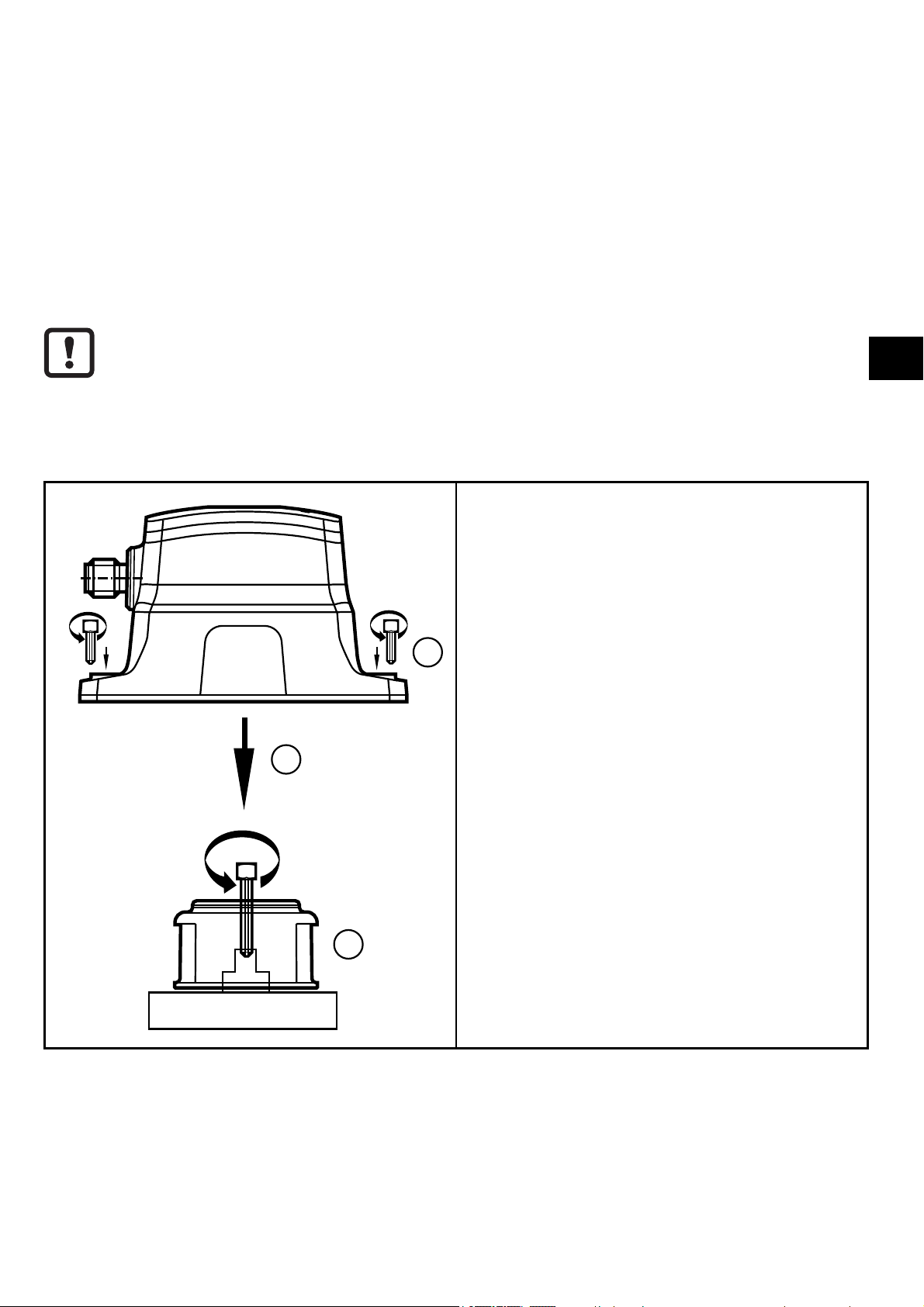
1: Use the two notches at the bottom of
the target puck as a mounting aid for a
precise positioning on the shaft. Align
target puck. The yellow indicator can
be rotated to show the desired open
3
2
position.
Fix the target puck to the valve head
using the supplied screw, tightening
torque 1.2 Nm.
2: Put the unit over the target puck.
3: Fix the unit to the actuator housing
UK
using the supplied screws, tightening
torque 1.5 Nm. Use an optional
mounting plate, depending on the
mechanical interface.
1
3
Page 4

5 Electrical connection
► Disconnect the installation from power and connect the unit.
3
1
5
4
2
+
L
2: OUT 2
4: OUT 1 / IO-Link
5: OUT 3
5
2
1
5.1 Switching functions
OUT1 (pin 4) Communication IO-Link
Switching output valve position open in SIO mode
OUT 2 (pin 2) Switching output valve position closed
OUT 3 (pin 5) Programmable:
- Switching output valve position open
- Switching output valve position closed
- Fault output
4
3
L
6 Function diagram
HYS HYS
OFF
1: Tolerance range
2: Leak warning range
3: Angle of the valve
SP = set point
HYS = hysteresis
SP
OFFON
4
Page 5

7 Operating and display elements
2
LED 5
1
LED 5
LED 1
LED PWR
LED 3
LED 4
1: Window for optical position indication (OPEN)
2: Inductive teach button
LED 1 yellow on switching status OUT1 – valve position open
LED 2 PWR green on voltage applied to the unit
LED 3 not used
LED 4 white on switching status OUT2 - valve position closed
LED 5 (ring) yellow on - switching status OUT1
blue on - switching status OUT2
UK
(colours programmable, yellow and blue preset at the
factory)
red flashing - fault in the unit
• no pulse pick-up available
• teach error - switch points SSC1 and SSC2 overlap
• end position not reached after set time has elapsed
• unit faulty
The LED colours in the table are the default colours and can be customised.
8 IO-Link
This unit has an IO-Link communication interface which enables direct access to
process and diagnostic data. In addition it is possible to set the parameters of the
unit while it is in operation. Operation of the unit via an IO-Link interface requires
an IO-Link master.
With a PC, suitable IO-Link software and an IO-Link adapter cable communication
is possible when the system is not in operation.
5
Page 6

The IODDs necessary for the unit's configuration, detailed information about
process data structure, diagnostic information, parameter addresses and the
necessary information about required IO-Link hardware and software can be
found at www.ifm.com.
9 Parameter setting
The parameters of the unit can be set both via the inductive teach button and via
IO-Link. To be able to use all the functions of the unit, an IO-Link communication
is required.
9.1 Parameter setting with IO-Link
Using an IO-Link capable parameter setting tool, the following options are
available:
- Reading current process values.
- Reading, changing and saving current parameter settings and transmitting
them to other units of the same type.
► Connect the unit via the IO-Link interface to a PC or PLC with suitable
parameter setting software.
ifm offers an IO-Link interface for the connection of the sensor via USB
port.
9.2 Setting parameters via IO-Link
Parameters Description Setting range
TI Select Teach selection SSC1 / SSC2 / SSC3
default = SSC1
SSC Param SP1 Switch point 1 -180.0°...179.9°
Steps 0.1°
SSC Config Logic Switch point logic 0 High active (NO)
1 Low active (NC)
SSC Config Hyst Switch point hysteresis 0.1°...5°
SSC Tol Tolerance of the switching
channel 1
Pin 5 /gr assignment Functional assignment for pin
5 / grey
0.1°...15.0°
0 = open / 1 = close /
2 = seat / -32768 error
6
Page 7

Power cycles Number of switching opera-
tions since delivery
0...2147483647
Operating hours Operating hours counter since
delivery
Valve offset Installation offset of the valve -180.0°...179.9°
SSC1 and SSC2
Swap switch points
Leak warning range Setting of the leak warning
Swap switch point
range
0...2147483647
Steps 0.1°
0.0...15°
UK
9.3 Manual parameter setting
9.3.1 Switch points
The unit has three switch points (SSCs). Two of them can be set via the inductive
teach button, the third switch point can be configured via IO-Link. Tolerance and
hysteresis can be set separately for each switch point, with an additional seal
monitoring for SSC2.
9.3.2 Parameter setting via inductive teach button
The sensor is adjusted using a metal object, e.g. a screwdriver.
Teach switch point 1 (SSC1) - valve open
► Activate teach button until the LED ring flashes yellow. Remove metal tool.
> LED ring yellow on, switch point is set.
Teach switch point 2 (SSC2) - valve closed
► Change valve position manually.
► Activate teach button until the LED ring flashes blue. Remove metal tool.
> LED ring blue on, switch point is set.
Swap switch points SSC1 and SSC2
► Activate teach button until the LED ring flashes yellow / blue. Remove metal
tool.
> LED ring yellow or blue on, switch point has been swapped.
7
Page 8

Lock unit
► Activate teach button (approx. 20 s) until the LED ring briefly flashes once.
> Unit is locked, no parameter setting possible.
Unlock unit
► Activate teach button (approx. 20 s) until the LED ring briefly flashes once.
10 Settings
1
2
2
Settings tolerance
Set a tolerance range between 0.1° and 15°
around the taught/set switch point.
1: Teach point
2: Tolerance width
Setting hysteresis
1
2
3
2
The hysteresis is around the tolerance range,
3
can be set between 0.1° and 5°.
1: Teach point
2: Tolerance width
3: Hysteresis
8
Page 9

Setting leak warning range
1
2
3
2
3
In the closed position SSC2, the unit features
leak monitoring in the range from 0.0° to 15°.
Deposits or wear can be detected. This leak
warning range lies within the tolerance range
and is activated and defined by selecting a
value (>0) which is deduced from the tolerance
range limits.
1: Teach point
2: Leak warning range
3: Tolerance width
UK
10.1 Timeout
Timeout indicates the maximum duration for closing or opening before the sensor
signals a blockage.
Adjustable time: between 0.1...30 s (factory setting 30 s).
In parallel, the parameters for the maximum closing and opening duration must be
adjusted manually (timeout ≥ maximum closing / opening duration).
10.2 Colours
For each switching output (SSC) different display colours of the LED ring can be
set individually.
You can choose among the following colours:
blue, green, cyan, red, magenta, yellow and white.
The colour feedback can be deactivated.
9
Page 10

10.3 Parameter setting pin 5
Pin 5 of the sensor can have different functions:
1. Switching output valve position open
2. Switching output valve position closed
3. Switching output seat position
4. Fault output
- Defect of the unit
- Puck not used
- Limit value for the timeout exceeded
10.4 Opening / closing duration
The minimum/maximum closing/opening duration of the drive can be freely set
and monitored. The sensor provides a warning via IO-Link if the actual value is
above or below the limit value.
Adjustable time: between 0.1...30 s
(factory setting: minimum opening/closing duration: 0 s; maximum opening/closing
duration: 30 s).
10
 Loading...