

IFM Electronic LR7300 Operating Manual

Operating instructions
Electronic level sensor
LR7300
80236090 / 00 03 / 2016
UK

2
Contents
1 Preliminary note ��������������������������������������������������������������������������������������������������� 4
1�1 Symbols used ������������������������������������������������������������������������������������������������4
2 Safety instructions �����������������������������������������������������������������������������������������������4
3 Items supplied������������������������������������������������������������������������������������������������������5
4 Functions and features ����������������������������������������������������������������������������������������5
4�1 Applications ���������������������������������������������������������������������������������������������������6
4�1�1 Restriction of the application area ��������������������������������������������������������6
5 Function ��������������������������������������������������������������������������������������������������������������� 7
5�1 Measuring principle ���������������������������������������������������������������������������������������7
5�2 Features of the unit ���������������������������������������������������������������������������������������� 8
5�2�1 Easy set-up �������������������������������������������������������������������������������������������8
5�2�2 Display functions ����������������������������������������������������������������������������������8
5�2�3 Switching functions ������������������������������������������������������������������������������� 8
5�2�4 Offset for indicating the real level in the tank ���������������������������������������� 9
5�2�5 Probes for different tank heights ����������������������������������������������������������� 9
5�2�6 Safe state ���������������������������������������������������������������������������������������������9
5�3 IO-Link ���������������������������������������������������������������������������������������������������������10
6 Installation���������������������������������������������������������������������������������������������������������� 11
6�1 Installation location / environment ��������������������������������������������������������������� 11
6�2 Installation of the probe �������������������������������������������������������������������������������14
6�3 Shortening of the probe �������������������������������������������������������������������������������15
6�4 Installation of the unit �����������������������������������������������������������������������������������15
6�4�1 Installation in closed metal tanks (without flange plate) ���������������������16
6�4�2 Installation in closed metal tanks (with flange plate) ��������������������������16
6�4�3 Installation in open tanks ��������������������������������������������������������������������17
6�4�4 Installation in plastic tanks ������������������������������������������������������������������ 18
6�5 Alignment of the sensor housing �����������������������������������������������������������������18
7 Electrical connection ������������������������������������������������������������������������������������������ 19
8 Operating and display elements ������������������������������������������������������������������������20
9 Menu ������������������������������������������������������������������������������������������������������������������ 21
9�1 Menu structure ��������������������������������������������������������������������������������������������� 21
9�2 Explanation of the menu ������������������������������������������������������������������������������ 22
10 Parameter setting ��������������������������������������������������������������������������������������������23

3
UK
10�1 Parameter setting in general ���������������������������������������������������������������������23
10�2 Entering the probe length (unit on delivery) �����������������������������������������������25
10�3 Configuration of the display �����������������������������������������������������������������������25
10�4 Offset setting ����������������������������������������������������������������������������������������������25
10�5 Setting of output signals ����������������������������������������������������������������������������26
10�5�1 Setting of the output function ������������������������������������������������������������ 26
10�5�2 Set the switching limits (hysteresis function) ������������������������������������ 26
10�5�3 Set the switching limits (window function) ����������������������������������������26
10�5�4 Setting of the switch-off delay ����������������������������������������������������������� 26
10�5�5 Response of the outputs in case of a fault ���������������������������������������26
10�5�6 Setting of the delay time after signal loss ����������������������������������������� 27
10�6 Reset all parameters to factory setting ������������������������������������������������������27
10�7 Changing the probe length ������������������������������������������������������������������������27
11 Operation ���������������������������������������������������������������������������������������������������������28
11�1 Operating indicators ���������������������������������������������������������������������������������� 28
11�2 Read the set parameters ���������������������������������������������������������������������������28
11�3 Changing the display unit in the Run mode �����������������������������������������������28
11�4 Error indications ����������������������������������������������������������������������������������������� 29
11�5 Output response in different operating states ��������������������������������������������30
12 Technical data and scale drawing �������������������������������������������������������������������� 30
12�1 Setting ranges ������������������������������������������������������������������������������������������30
13 Servicing ���������������������������������������������������������������������������������������������������������� 31
14 Applications������������������������������������������������������������������������������������������������������32
14�1 Minimum level monitoring with early warning and alarm ���������������������������32
14�2 Pumping station / empty the tank with overflow protection ������������������������33
14�3 Storage tank ����������������������������������������������������������������������������������������������34
15 Factory setting �������������������������������������������������������������������������������������������������35

4
1 Preliminary note
1.1 Symbols used
► Instructions
> Reaction, result
[…] Designation of keys, buttons or indications
→ Cross-reference
Important note
Non-compliance may result in malfunction or interference�
Information
Supplementary note�
2 Safety instructions
• Please read this document prior to set-up of the unit� Ensure that the product is
suitable for your application without any restrictions�
• If the operating instructions or the technical data are not adhered to, personal
injury and/or damage to property can occur�
• Improper or non-intended use may lead to malfunctions of the unit or to
unwanted effects in your application� That is why installation, electrical
connection, set-up, operation and maintenance of the unit must be carried out
by qualified personnel authorised by the machine operator�
• In order to guarantee the correct operation of the unit, it is necessary to use the
unit in media for which it is sufficiently resistant (→ Technical data).
• The responsibility as to the suitability of the unit for the application lies with the
operator� The manufacturer assumes no liability for consequences of misuse by
the operator�
• Improper installation and use of the unit result in a loss of the warranty claims
• The unit may cause radio interference in domestic areas� If interference occurs,
the user must take appropriate remedial actions�
• The unit complies with the standard EN 61000-6-4 and is a class A product�
The radiated energy of the microwaves is, for example, much below that of
mobile phones� According to the current state of science the operation of the
unit can be classified to be harmless to human health�
5
UK
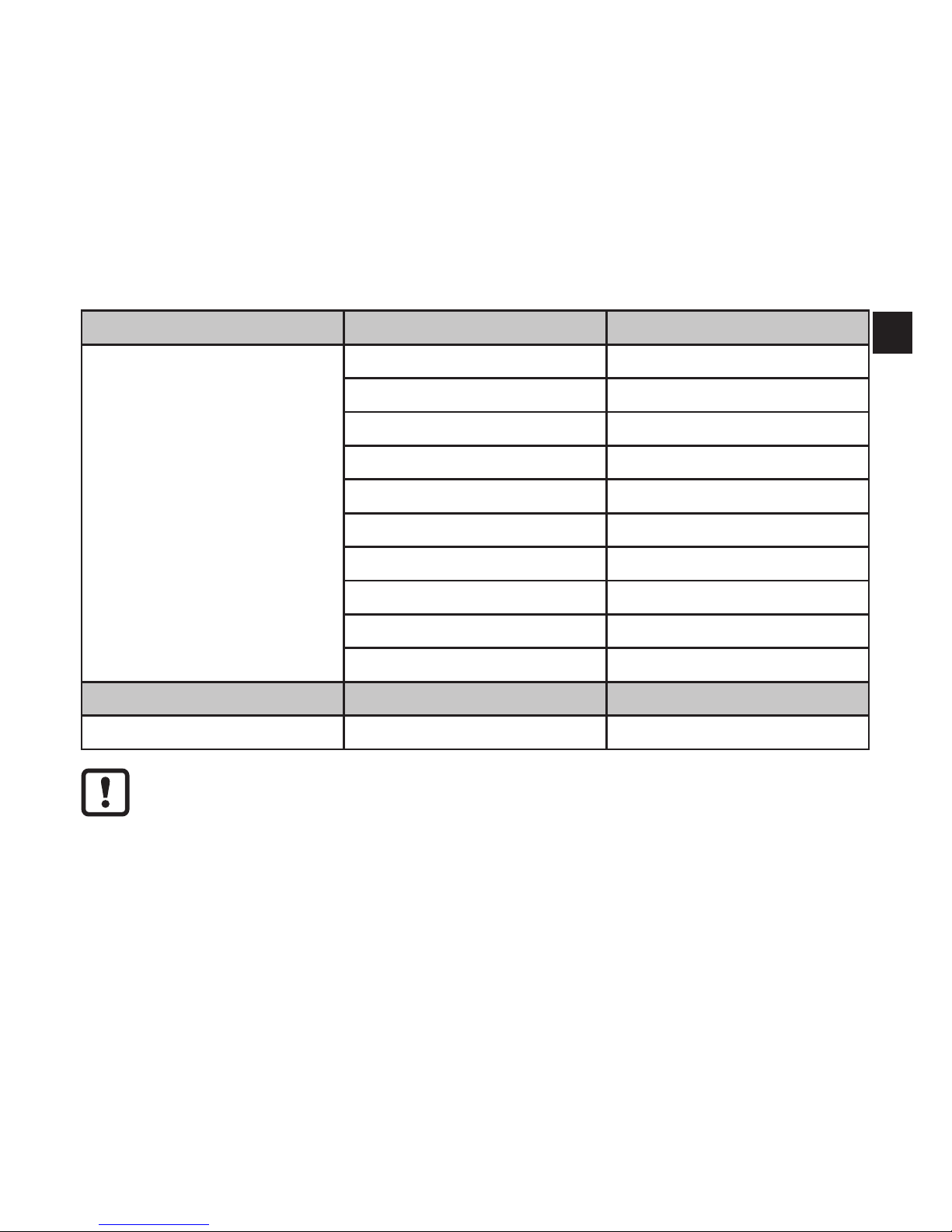
3 Items supplied
• Level sensor LR7300
• Operating instructions
In addition, the following is necessary for installation and operation:
• 1 rod
• Mounting material (if necessary, a launching plate → 4 Functions and features)
The following components are available as accessories:
Rods Length (cm / inch) Order number
15 / 5�9 E43225
24 / 9�5 E43203
30 / 11�8 E43226
45 / 17�7 E43204
50 / 19�7 E43227
70 / 27�6 E43205
100 / 39�4 E43207
120 / 47�2 E43208
140 / 55�1 E43209
160 / 63�0 E43210
Flange plate Size / process connection Order number
73 - 90 / ¾" NPT E43206
Only use rods from ifm electronic gmbh� The optimum function is not
ensured when using components from other manufacturers�
4 Functions and features
The unit continuously detects the level in tanks and generates output signals
according to the parameter settings�
2 switching outputs are available� They can be set separately�

6
For correct function the unit needs a large enough metal launching plate� It
is necessary for transferring the microwave pulse to the tank with optimum
transmission power�
The flange plates that are available as accessories are not sufficient as
launching plates (for suitable launching plates → 6.4).
For installation in closed metal tanks, the tank lid serves as a launching
plate� For installation in open metal tanks, tanks made of plastic or metal
tanks with plastic lids a sufficiently large fixing plate, a metal plate or
similar must be used (→ 6.4.3 / → 6.4.4).
Furthermore, minimum distances to tank walls, objects in the tank, bottom
of the tank and further level sensors must be adhered to (→ 6.1).
4.1 Applications
• Water, water-based media
Application examples:
• Detection of coolant emulsion in a machine tool�
• Detection of cleaning liquid in a parts cleaning system�
4.1.1 Restriction of the application area
Incorrect measurements or signal loss may be caused by the following
media:
- Highly absorbing surfaces (e�g� foam)�
- Intensely bubbling surfaces�
- Media which are very inhomogeneous, separate from each other thus
forming separation layers (e�g� oil layer on water)�
► Check the function by performing an application test�
► Installation in a steady area (→ 6.1).
> In case of signal loss, the unit displays [E�033] and switches the
outputs to a defined state (→ 11.5).
• The unit is not suitable for media with a dielectric constant < 20 (e�g� oils, fats,
plastic granulates, bulk material)�
• If the unit is to be used in acids or alkalis, in hygienic areas or in electroplating
applications: first check the compatibility of the product materials (→ Technical
data sheet) with the media to be monitored�
7
UK
• The unit is not suitable for applications where the probe is subjected to
permanent and high mechanical stress (e�g� strongly moving viscous media or
strongly flowing media)�
• Use preferably in metal tanks� When installed in plastic tanks, deterioration
caused by electromagnetic interference may occur (noise immunity according
to EN61000-6-2)�
Corrective measures: → 6.4.4.
5 Function
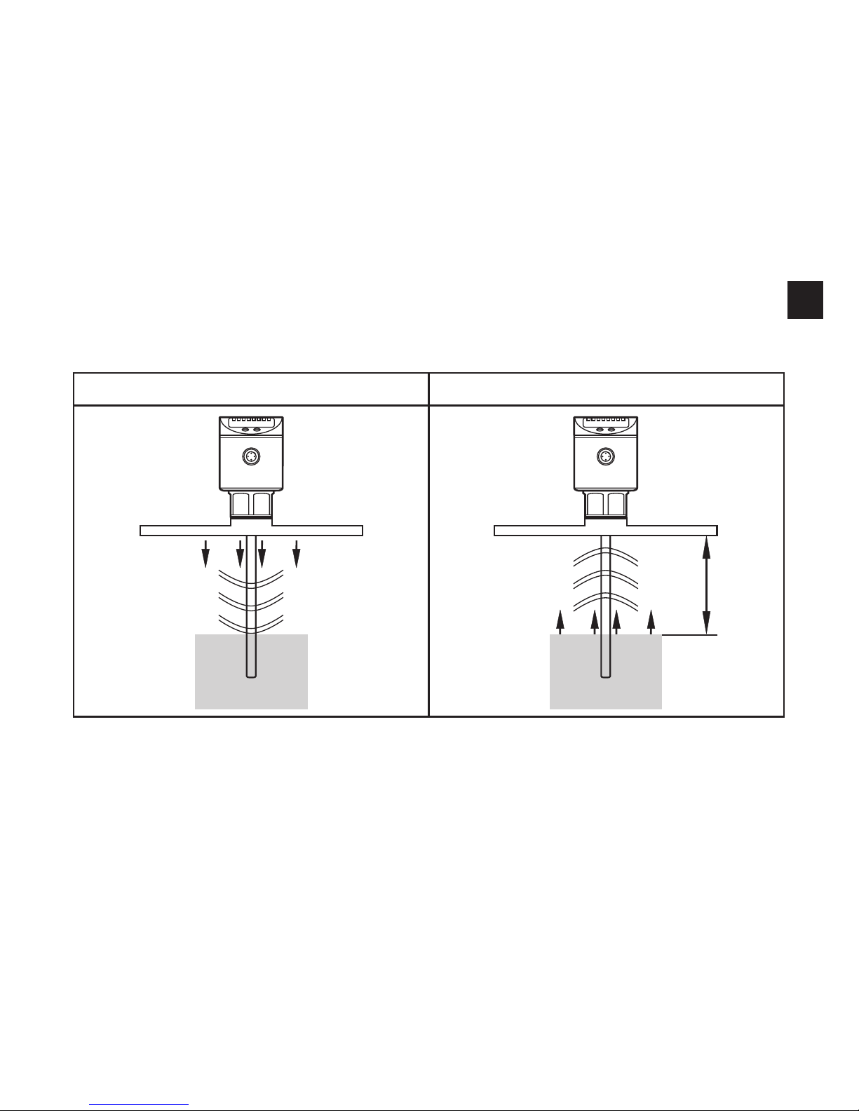
5.1 Measuring principle
Fig. 5-1 Fig. 5-2
D
The unit operates to the principle of guided wave radar� It measures the level
using electromagnetic pulses in the nanosecond range�
The pulses are transmitted by the sensor head and guided along the rod (fig� 5-1)�
When they hit the medium to be detected they are reflected and guided back
to the sensor (fig� 5-2)� The time between transmitting and receiving the pulse
directly relates to the travelled distance (D) and the current level� The reference for
distance measurement is the lower edge of the process connection�

8
5.2 Features of the unit
5.2.1 Easy set-up
• When operating voltage is applied to the unit for the first time, the probe length
must be entered. Then the unit is ready for operation (→ 10.2).
• If necessary, parameters for the output signals and optimisation of the
monitoring functions can be set (→ 10.3 to → 10.5).
• All settings can also be carried out before installation of the unit�
• Reset to the factory settings is possible�
• Electronic lock can be set to prevent unintentional operations�
5.2.2 Display functions
The unit displays the current level, either in cm, inch or in percent of the final
value of the measuring range� Factory setting: inch� The display unit is defined by
programming (→ 10.3). In the Run mode, it can be temporarily switched between
length indication (cm / inch) and percentage:
► Briefly press [Set]�
> The selected unit is displayed for 15 s, the corresponding LED is lit� With each
push of the button the display type is changed�
The set unit of measurement and the switching status of the outputs are indicated
by LEDs�
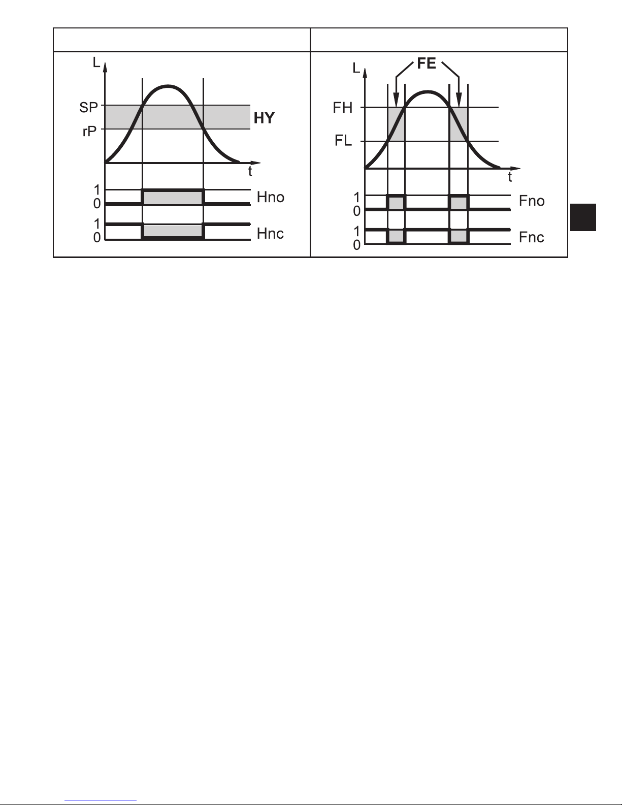
5.2.3 Switching functions
The unit signals via two switching outputs OUT1 / OUT2 that a set limit level
has been reached or that the level is below the limit value� For each output the
following switching functions can be selected:
• Hysteresis function / normally open (fig� 5-3): [OUx] = [Hno]�
• Hysteresis function / normally closed (fig� 5-3): [OUx] = [Hnc]�
First the set point (SPx) is set, then the reset point (rPx) with the requested
difference�
• Window function / normally open (fig� 5-4): [OUx] = [Fno]�
• Window function / normally closed (fig� 5-4): [OUx] = [Fnc]�
The width of the window can be set by means of the difference between
FHx and FLx� FHx = upper value, FLx = lower value�
9
UK
Fig. 5-3 Fig. 5-4
L = level; HY = hysteresis; FE = window
• For each switching output a switch-off delay of max� 60 s can be set (e�g� for
especially long pump cycles)�
5.2.4 Offset for indicating the real level in the tank
The zone between tank bottom and lower edge of the probe can be entered as
offset value [OFS]� So display and switch points refer to the actual level�
5.2.5 Probes for different tank heights
• The unit can be installed in tanks of different sizes� Probes in different lengths
are available� To adapt to the tank height, each probe can be shortened� The
minimum probe length is 10 cm, the maximum probe length is 160 cm�
• Probe and housing can be rotated without restriction� This enables easy
installation and orientation of the head of the unit after installation�
5.2.6 Safe state
• In case of a fault a safe state can be defined for each output�
• If a fault is detected or if the signal quality is below a minimum value, the
outputs pass into the "safe state"� For this case the response of the outputs can
be set via the parameters [FOU1], [FOU2]�
• Temporary loss of signal caused e�g� by turbulence or foam formation can be
suppressed by a delay time (→ 10.5.6 [dFo]). During the delay time the last
measured value is frozen� If the measured signal is received again in sufficient
strength within the delay time, the unit continues to work in normal operation�

10
If, however, it is not received again in sufficient strength within the delay time,
the outputs pass into the safe state�
In case of heavy foam formation and turbulence, note the examples of how
to create a steady area (→ 6.1).
5.3 IO-Link
General information
This unit has an IO-Link communication interface which requires an IO-Linkcapable module (IO-Link master) for operation�
The IO-Link interface enables direct access to the process and diagnostic data
and provides the possibility to set the parameters of the unit during operation� In
addition communication is possible via a point-to-point connection with a USB
adapter cable�
Further information about IO-Link is available at www�ifm�com/gb/io-link�
Device-specific information
You will find the IODDs necessary for the configuration of the IO-Link unit and
detailed information about process data structure, diagnostic information and
parameter addresses at www�ifm�com/gb/io-link�
Parameter setting tools
You will find all necessary information about the required IO-Link hardware and
software at www�ifm�com/gb/io-link�

11
UK
6 Installation
6.1 Installation location / environment
• Vertical installation from the top is preferred�
• For a safe function, the unit requires a launching plate (→ 6.4).
• For optimum operation the unit is to be installed as near as possible to the tank
wall� Distance between the rod and the tank wall: minimum 40 mm, maximum
300 mm�
• The following minimum distances between the rod and tank walls, objects in
the tank (B), tank bottom and other level sensors must be adhered to:
50mm
10mm
100mm
B
40mm
• For tank walls which are not straight, steps, supports or other structures in the
tank a distance of 50 mm to the tank wall must be adhered to�
• For probe lengths > 70 cm the rod can be considerably deflected by movement
of the medium� To avoid contacting the tank wall or other structures in the tank
in such cases, the minimum distances should be increased� Reference values:
Probe length Distance to the tank wall or structures in the tank
70���100 cm 100 mm
100���160 cm 180 mm
• If the medium is strongly polluted, there is the risk that a bridge forms
between the rod and the tank wall or structures in the tank� To avoid incorrect
measurements: adhere to increased minimum distances depending on type
and intensity of the soiling�
 Loading...