

IFM Electronic LR2059 Operating Instructions Manual
Operating instructions
Electronic level sensor
LR2059
UK
80231784 / 01 01 / 2018

Contents
1 Preliminary note ................................................................................................... 5
1.1 Symbols used ................................................................................................5
2 Safety instructions ...............................................................................................5
3 Items supplied......................................................................................................6
4 Getting started .....................................................................................................6
5 Functions and features ........................................................................................7
5.1 Applications ...................................................................................................7
5.2 Restriction of the application area .................................................................7
6 Function ............................................................................................................... 8
6.1 Measuring principle .......................................................................................8
6.2 Outputs ..........................................................................................................9
6.3 Other features of the unit ............................................................................... 9
6.3.1 Display functions ..................................................................................9
6.3.2 Analogue function ..............................................................................10
6.3.3 Switching functions ............................................................................. 12
6.3.4 Damping function ................................................................................12
6.3.5 Probes for different tank heights ......................................................... 13
6.3.6 Defined state in case of a fault ...........................................................13
6.3.7 IO-Link ................................................................................................14
6.3.8 Simulation functions ...........................................................................14
7 Installation .........................................................................................................14
7.1 Installation location / environment ...............................................................14
7.2 Unit with single probe ..................................................................................14
7.2.1 Minimum distances for installation in closed metal tanks ................... 15
7.2.2 Installation in pipes .............................................................................15
7.2.3 Applications with viscous and fast flowing media ...............................16
7.2.4 Fill openings .......................................................................................16
7.2.5 Heavy soiling ......................................................................................17
7.2.6 Heavy foam build-up and turbulence .................................................. 17
7.2.7 Notes on tank adjustment ................................................................... 18
7.3 Unit with coaxial probe ................................................................................19
7.4 Installation of the probe ...............................................................................20
7.4.1 Attaching the probe .............................................................................20
2

7.4.2 Installation of the coaxial pipe ............................................................21
7.5 Probe length ...............................................................................................22
7.5.1 Shorten the probe ............................................................................... 22
7.5.2 Determine probe length L for single probes........................................23
7.5.3 Shortening of the coaxial pipe ............................................................23
7.5.4 Determine probe length L for coaxial probes ......................................24
7.6 Installation of the unit with single probe .......................................................24
7.6.1 Installation to G¾ process connection directly in the tank lid ............. 25
7.6.2 Installation in the tank lid using a G¾ flange plate .............................25
7.6.3 Installation in open metal tanks ..........................................................26
7.6.4 Installation in plastic tanks .................................................................. 27
7.7 Installation of the unit with coaxial probe ..................................................... 28
7.8 Alignment of the sensor housing .................................................................28
8 Electrical connection .......................................................................................... 29
9 Operating and display elements ........................................................................30
10 Menu ................................................................................................................ 31
10.1 Menu structure ........................................................................................... 31
10.2 Explanation of the menu ............................................................................ 33
10.2.1 Main menu [I] .................................................................................... 33
10.2.2 EF level (extended functions) [II] ......................................................33
UK
10.2.3 CFG level (configuration) [III] ............................................................34
10.2.4 ENV level (environment) [IV] ............................................................34
10.2.5 SIM level (simulation) [V] .................................................................. 34
11 Parameter setting .............................................................................................35
11.1 Parameter setting in general ...................................................................... 35
11.2 Basic settings (set-up) ...............................................................................37
11.2.1 Enter type of probe used ..................................................................37
11.2.2 Enter probe length ............................................................................37
11.2.3 Set to the medium .............................................................................38
11.2.4 Carry out tank adjustment .................................................................38
11.3 Configure display (optional) .......................................................................39
11.4 Set output signals ......................................................................................39
11.4.1 Set output function for OUT 1 ...........................................................39
11.4.2 Set switching limits (hysteresis function) ..........................................39
11.4.3 Set switching limits (window function) ..............................................39
11.4.4 Set switch-on delay for switching outputs ......................................... 40
3

11.4.5 Set switch-off delay for switching outputs .........................................40
11.4.6 Set output function for OUT2 ............................................................40
11.4.7 Scale analogue signal .......................................................................40
11.4.8 Set output logic for switching outputs ...............................................40
11.4.9 Set response of the outputs in case of a fault ...................................41
11.4.10 Set damping for the measured signal .............................................41
11.4.11 Set delay time in case of a fault ......................................................41
11.5 Reset all parameters to factory setting ......................................................41
11.6 Change basic settings ................................................................................42
11.6.1 Change the type of probe used ........................................................42
11.6.2 Re-enter probe length ....................................................................... 42
11.6.3 Set to another medium .....................................................................42
11.7 Simulation ..................................................................................................43
11.7.1 Set simulation value ..........................................................................43
11.7.2 Set simulation duration .....................................................................43
11.7.3 Switch simulation on / off ..................................................................43
12 Operation ......................................................................................................... 44
12.1 Operation with single probe ....................................................................... 44
12.2 Operation with coaxial probe .....................................................................44
12.3 Function check ..........................................................................................44
12.4 Operation indication ...................................................................................45
12.5 Read the set parameters ...........................................................................45
12.6 Change the display unit in the operating mode .........................................46
12.7 Error indications .........................................................................................46
12.8 Output response in different operating states ............................................ 47
13 Technical data .................................................................................................. 47
13.1 Setting ranges ..........................................................................................47
14 Maintenance / transport ................................................................................... 48
15 Factory setting .................................................................................................49
16 Notes on parameter setting via IO-Link ...........................................................50
16.1 Application example ...................................................................................50
16.2 Unit locking / data storage (as from IO-Link V1.1) .....................................51
4

1 Preliminary note
1.1 Symbols used
► Instructions
> Reaction, result
[…] Designation of keys, buttons or indications
→ Cross-reference
Important note
Non-compliance may result in malfunction or interference.
Information
Supplementary note.
2 Safety instructions
UK
• Read this document before setting up the product and keep it during the entire
service life.
• The product must be suitable for the corresponding applications and
environmental conditions without any restrictions.
• Only use the product for its intended purpose (→ Functions and features).
• Only use the product for permissible media (→ Technical data sheet).
• If the operating instructions or the technical data are not adhered to, personal
injury and/or damage to property may occur.
• The manufacturer assumes no liability or warranty for any consequences
caused by tampering with the product or incorrect use by the operator.
• Installation, electrical connection, set-up, operation and maintenance of the
product must be carried out by qualified personnel authorised by the machine
operator.
• Protect units and cables effectively against damage.
5

3 Items supplied
• 1 LR2059 level sensor
• 1 operating instructions
In addition, the following is necessary for installation and operation
(→ Accessories):
• 1 probe (→ 12.1)
• as an option: 1 coaxial pipe (→ 12.2)
• mounting material (if necessary, a launching plate (→ 12.1)
► In the event of incomplete or damaged items supplied please contact ifm
electronic.
► Only use accessories from ifm electronic.
Accessories: www.ifm.com
The optimum function is not ensured when using components from other
manufacturers.
4 Getting started
For the most frequent applications the quick set-up described below is possible.
The quick set-up does not replace observance of the other chapters.
► Install the unit correctly:
Installation distances (→ 7.1), Electrical connection (→ 8).
► Setting the type of probe, probe length and medium (→ 11.2).
> The unit is ready for operation.
Without changes = factory settings active (→ 15).
Change of the factory settings (→ 11).
► As an option, carry out a tank adjustment (→ 11.2.4).
► If necessary, make more settings for adaptation to the application
(→ 11.3) and (→ 11.4).
► Check whether the unit operates correctly.
6

5 Functions and features
The unit continuously detects the level in tanks.
5.1 Applications
• Water, water-based media
• Oils, oil-based media (only for operation with coaxial probe)
• Compatible with G ¾ process connections
Application examples:
- Detection of cleaning liquid in a parts cleaning system
- Monitoring of hydraulic oil in a hydraulic power unit (only for operation with
coaxial probe)
- Detection of cooling water in an industrial cooling system
- Detection of hot glue in corrugated cardboard manufacture
UK
The unit complies with the standard EN 61000-6-4 and is a class A product.
The unit may cause radio interference in domestic areas. If interference occurs,
the user must take appropriate actions.
The microwave energy radiated by the unit is much below that of mobile
phones.
According to the current state of science the operation of the unit can be
classified to be harmless to human health.
5.2 Restriction of the application area
Incorrect measurements may be caused by the following media:
- Highly absorbing surfaces (e.g. foam).
- Intensely bubbling surfaces.
- Media which are very inhomogeneous, separate from each other thus
forming separation layers (e.g. oil layer on water).
► Check the function by performing an application test.
► Installation in a steady area (→ 7.2.6).
> In case of signal loss, the unit displays [SEnS] and switches the
outputs to a defined state (→ 12.8).
• The unit is not suitable for bulk materials (e.g. plastic granulates).
7
• The unit is not suitable for applications where the probe is subjected to
permanent and high mechanical stress (e.g. fast moving viscous media or fast
flowing media).
• In case of operation with single probe: When used in plastic tanks, deterioration
caused by electromagnetic interference may occur (noise immunity to
EN61000-6-2). Remedy: (→ 7.6.4)
• In case of operation with coaxial probe: not suitable for soiled or viscous media,
media containing solid particles and media prone to formation of deposit.
Maximum viscosity: 500 mPa · s.
6 Function
6.1 Measuring principle
Fig. 6-1 Fig. 6-2
D
The unit operates on the principle of guided wave radar. It measures the level
using electromagnetic pulses in the nanosecond range.
The pulses are transmitted by the sensor head and guided along the probe (Fig.
6-1). When they hit the medium to be detected they are reflected and guided back
to the sensor (Fig. 6-2). The time between transmitting and receiving the pulse
directly relates to the travelled distance (D) and the current level. The reference for
distance measurement is the lower edge of the process connection.
The figures show the operation with single probe. In case of operation with
8
a coaxial probe, the guided wave runs only along the inside of the coaxial
pipe.

6.2 Outputs
The unit generates output signals according to the parameter setting. 2 outputs
are available. They can be set separately.
OUT1 switching signal for level limit / IO-Link (→ 6.3.7)
OUT2 • analogue signal proportional to level 4...20 mA / 20...4 mA
or
• switching signal for level limit
UK
6.3 Other features of the unit
• Increased temperature range, increased protection rating (→ Technical data
sheet)
• Special operating mode for media with increased foam build-up (→ 11.2.3)
• Tank adjustment enables suppression of undesired interference
(e.g. caused by structures in the tank or when mounted in a connection piece
(→ 11.2.4))
• Display of the level and the switching status via display / LEDs
• IO-Link function (→ 6.3.7)
6.3.1 Display functions
The unit displays the current level, either in mm or in percent of the scaled
measuring range. Factory setting: mm.
The display unit is defined by programming (→ 11.3).
In the operating mode, the user can temporarily switch between the length display
(mm) and percentage (→ 12.6).
The set unit of measurement and the switching status of the outputs are indicated
by LEDs (→ 9).
9
6.3.2 Analogue function
The unit provides an analogue signal proportional to level. The analogue output
(OUT2) can be configured.
• [OU2] defines the output function of the analogue output:
- current output rising ([ou2] = [I]) or
- current output falling ([ou2] = [InEG]) (→ 11.4.6)
• The analogue start point [ASP2] defines at which measured value the analogue
start value*) is provided (→ 11.4.7).
• The analogue end point [AEP2] defines at which measured value the analogue
end value*) is provided (→ 11.4.7).
*) The analogue start value is 4 mA with [ou2] = [I] or 20 mA with [ou2] =
[InEG].
The analogue end value is 20 mA with [ou2] = [I] or 4 mA with [ou2] = [InEG].
Minimum distance between [ASP2] and [AEP2] = 20 % of the active zone.
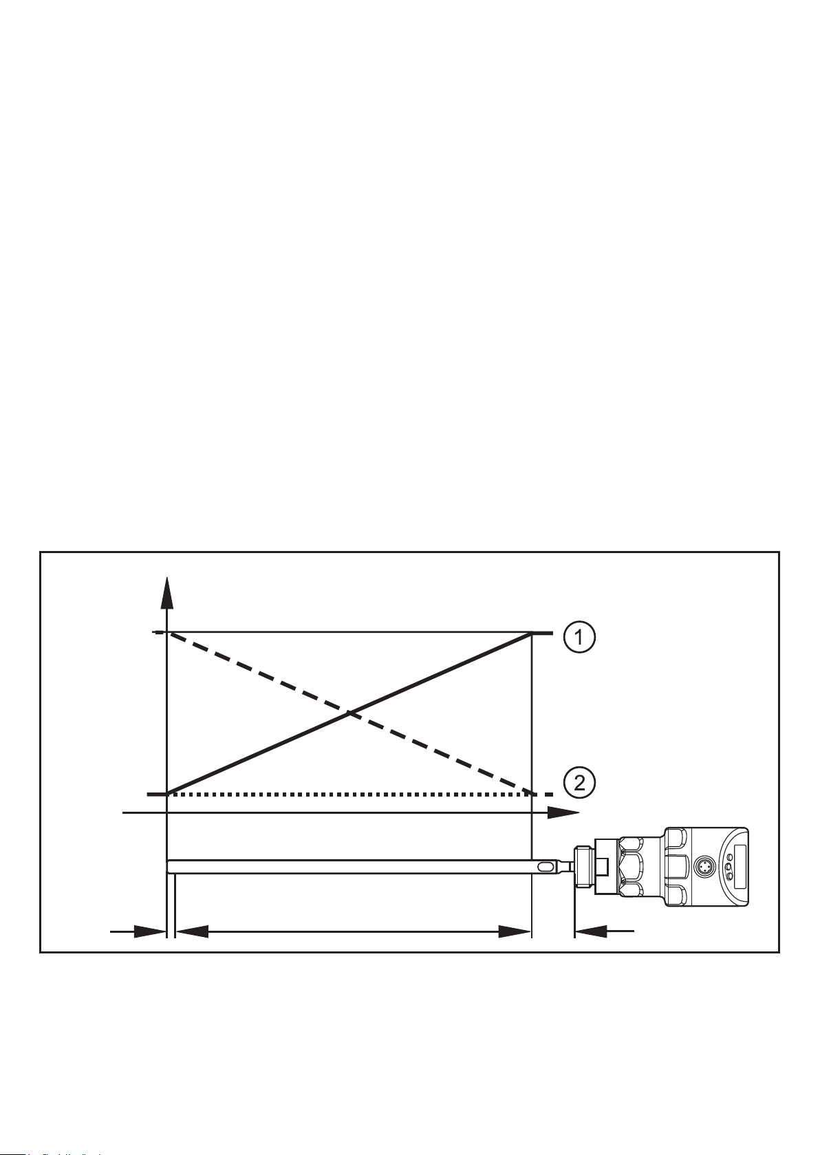
Curve of the analogue signal (factory setting):
I [mA]
20
4
L
10
I2 I1
A
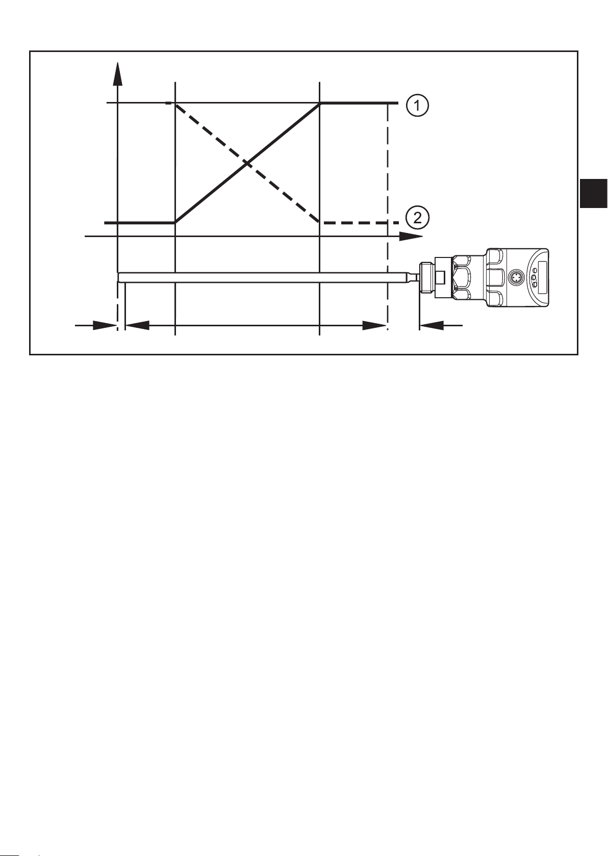
Curve of the analogue signal (measuring range scaled):
I [mA]
ASP2 AEP2
20
4
L
UK
A
L: level
A: active zone = probe length L - (I1 + I2)
I1: inactive zone 1 ASP2: analogue start point
I2: inactive zone 2 (→ Technical data sheet) AEP2: analogue end point
①:
②:
[ou2] = I (factory setting)
[ou2] = [InEG]
I1 I2
Additional information about the analogue output: (→ 12.8)
Note the tolerances and accuracies during the evaluation of the analogue signal
(→ Technical data sheet).
11
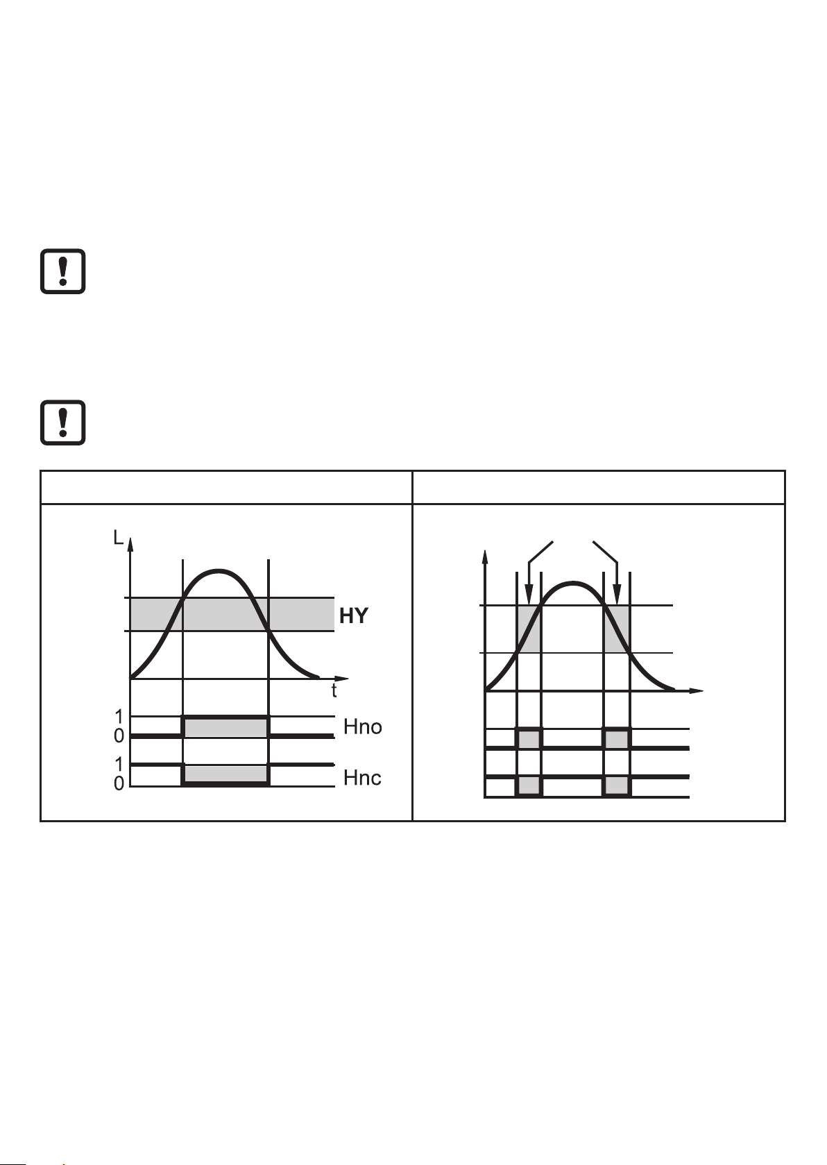
6.3.3 Switching functions
Via switching output OUT1 (factory setting) or additionally via OUT2 (can be set)
the unit signals that a set limit level has been reached or that the level is below the
limit. The following switching functions can be selected:
• Hysteresis function / normally open (Fig. 6-3): [oux] = [Hno]
• Hysteresis function / normally closed (Fig. 6-3): [oux] = [Hnc]
First the set point (SPx) is set, then the reset point (rPx) with the requested
difference.
• Window function / normally open (Fig. 6-4): [oux] = [Fno]
• Window function / normally closed (Fig. 6-4): [oux] = [Fnc]
The width of the window can be set by means of the difference between
FHx and FLx. FHx = upper value, FLx = lower value.
L:
HY:
FE:
SP
rP
level
hysteresis
window
Fig. 6-3 Fig. 6-4
FE
L
FH
FL
1
0
1
0
t
Fno
Fnc
• The adjustable limits (e.g. SP / rP) always refer to the lower edge of the probe.
• For the switching output a switch-on and switch-off delay of max. 60 s can be
set (e.g. for especially long pump cycles) (→ 11.4.4).
6.3.4 Damping function
With unsteady level (e.g. turbulence, wave movements...) display and output
response may be damped. During damping the determined level values are
12

"smoothed" by means of a mean filter; the result is a steady curve. Damping
can
be set by means of the parameter [dAP] (→ 11.4.10).
[dAP] indicates in seconds after what time 63 % of the final value is reached in the
event of a sudden jump. After 5 x [dAP] almost 100 % has been reached.
6.3.5 Probes for different tank heights
The unit can be installed in tanks of different sizes. Probes in different lengths are
available. To adapt to the tank height, each probe can be shortened. The minimum
UK
probe length is 150 mm, the maximum probe length 2000 mm.
6.3.6 Defined state in case of a fault
• In case of a fault a state can be defined for each output.
• If a fault is detected or if the signal quality is below a minimum value, the
outputs pass into a defined state, according to NAMUR recommendation in
case of the analogue output. For this case the response of the outputs can be
set via the parameters [FOU1], [FOU2] (→ 11.4.9).
• Temporary loss of signal caused e.g. by turbulence or foam build-up can be
suppressed by a delay time (parameter [dFo] (→ 11.4.11)). During the delay
time the last measured value is frozen. If the measured signal is received again
in sufficient strength within the delay time, the unit continues to work in normal
operation. If, however, it is not received again in sufficient strength within the
delay time, the outputs pass into the defined state.
In case of heavy foam build-up and turbulence, note the examples of how
to create a steady area (→ 7.2.6).
13

6.3.7 IO-Link
This unit has an IO-Link communication interface which requires an IO-Link
capable module (IO-Link master) for operation.
The IO-Link interface enables direct access to the process and diagnostic data
and provides the possibility to set the parameters of the unit during operation.
In addition, communication is possible via a point-to-point connection with a USB
IO-Link master.
The IODDs necessary for the configuration of the unit, detailed information about
process data structure, diagnostic information, parameter addresses and the
necessary information about required IO-Link hardware and software can be
found at www.ifm.com.
6.3.8 Simulation functions
Various levels and errors can be simulated for set-up, maintenance or interference
reduction. The duration of the simulation can be selected (1 min...1 h). The
simulation can be started manually and runs until it is stopped manually or the
set time elapses. During the simulation the outputs respond according to the
simulated process values (→ 11.7) to (→ 11.7.3)
.
7 Installation
7.1 Installation location / environment
• Vertical installation from the top is preferred.
7.2 Unit with single probe
► Observe the notes on tank adjustment (→ 7.2.7).
• For installation in open tanks (→ 7.6.3)
• For installation in plastic tanks (→ 7.6.4)
14
7.2.1 Minimum distances for installation in closed metal tanks
Fig. 7-1 Fig. 7-2
without adjustment
D
A2A3
B
UK
A1
Installation distances with adjustment (→
7.2.7)
A1: 10 mm *) A1: 10 mm *)
A2: 20 mm A2: 50 mm
A3: 20 mm to structures in the tank (B)
50 mm to other sensors type LR
D:
*) Alternatively: Fix probe at the tank bottom. Observe notes (→ 7.2.3).
ø 30 mm if installed in a connection
piece
Installation distances without adjustment *)
A3: 50 mm to structures in the tank (B)
50 mm to other sensors type LR
D: no connection piece allowed
according to Fig. 7-2
7.2.2 Installation in pipes
► The internal pipe diameter d must at least have the following value:
d With adjustment Without adjustment
ø 100 mm with [MEdI] = [HIGH]
Metal pipe
ø 30 mm
ø 200 mm with [MEdI] = [MId] (→ 11.2.3)
Plastic pipe *)
*) Observe notes (→ 7.6.4)
Depending on the operating conditions (flow) and mechanical design of
the pipe the use of centring pieces is recommended (→ Accessories).
ø 200 mm
15

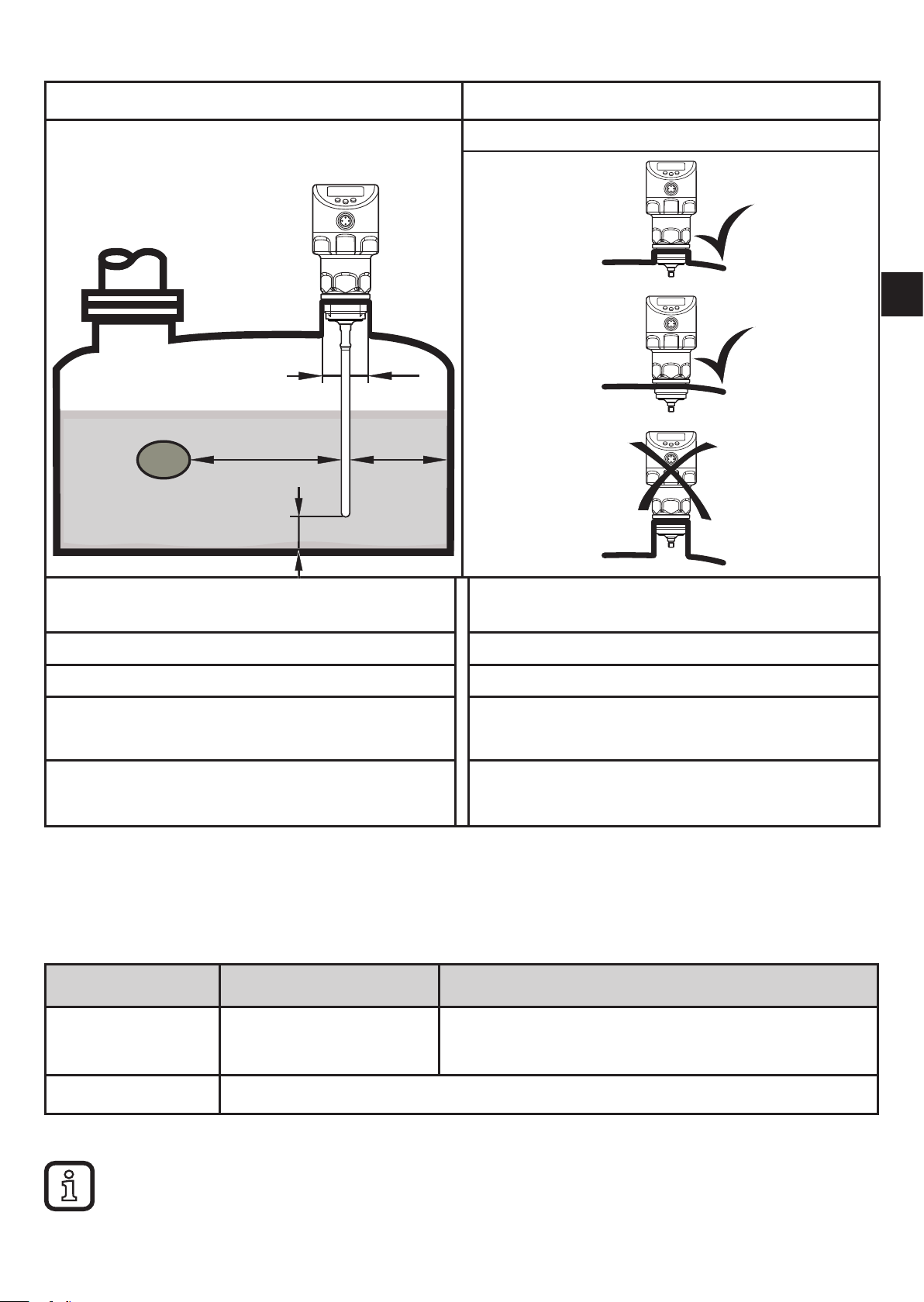
7.2.3 Applications with viscous and fast flowing media
► If possible, install the unit in a bypass pipe / still pipe (→ 7.2.2).
► In addition, the following aspects have to be considered:
► Probe must not be in contact with the
tank wall / structures.
► Increase lateral minimum distances
according to the probe length and the
lateral deflection to be expected.
► If possible, fix the probe at the
tank bottom so that it is electrically
conductive. This can be done by means
of a sleeve or similar devices (Fig. 7-3).
► Check the correct function (in particular
with empty tank).
Fig. 7-3
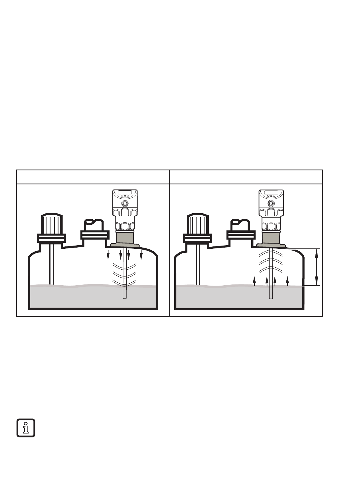
7.2.4 Fill openings
Do not install the unit in the immediate vicinity of a fill opening (Fig. 7-4).
If possible, install a fill pipe (A) in the tank (Fig. 7-5). Keep to the indicated
installation distances; if necessary, carry out a tank adjustment.
Fig. 7-4 Fig. 7-5
A
16
 Loading...