

IFM Electronic LK8122, LK8123, LK8124 Operating Instructions Manual
Operating instructions
Electronic level sensor
LK81xx
80264351 / 00 06 / 2017
UK

2
Contents
1 Preliminary note ................................................................................................... 4
1.1 Symbols used ................................................................................................4
2 Safety instructions ...............................................................................................4
3 Functions and features ........................................................................................5
3.1 Applications ...................................................................................................5
3.2 Restriction of the application area ................................................................5
4 Getting started .....................................................................................................6
4.1 Example configuration 1 ................................................................................6
4.2 Example configuration 2 ................................................................................7
5 Function ............................................................................................................... 8
5.1 Measuring principle .......................................................................................8
5.2 Operating principle / features of the unit ........................................................8
5.2.1 Operating modes ..................................................................................9
5.2.2 Notes on the integrated overflow prevention ........................................ 9
5.2.3 Display and switching functions ..........................................................10
5.2.4 Offset for indicating the real level in the tank ...................................... 11
5.2.5 Defined state in case of a fault ........................................................... 11
5.2.6 IO-Link function .................................................................................. 11
6 Installation .........................................................................................................13
6.1 Notes on installation instructions for operation with overflow prevention ...14
6.2 Installation instructions for operation without overflow prevention ..............15
6.2.1 Installation in the inactive zone ...........................................................15
6.2.2 Installation in the active zone .............................................................16
6.3 Further notes on installation / accessories ..................................................17
6.3.1 Marking of the installation height ........................................................17
7 Electrical connection .......................................................................................... 18
8 Operating and display elements ........................................................................20
9 Menu .................................................................................................................. 21
9.1 Menu ............................................................................................................ 21
10 Parameter setting ............................................................................................22
10.1 Parameter setting in general .....................................................................22
10.2 Basic settings ...........................................................................................23

3
UK
10.2.1 Setting the unit of measurement [uni] ............................................... 23
10.2.2 Set the offset [OFS] ..........................................................................23
10.2.3 Set the medium [MEdI] .....................................................................24
10.2.4 Set the overflow prevention [OP] .................................................... 24
10.2.5 Adjust the overflow prevention [cOP] ................................................25
10.3 Setting of output signals ............................................................................26
10.3.1 Set output function [oux] for OUTx ..................................................26
10.3.2 Define the switching limits [SPx] / [rPx] (hysteresis function) ........... 26
10.3.3 Define switching limits [FHx] / [FLx] (window function) .....................27
10.3.4 Set the switching delays [dSx] for switching outputs ........................ 27
10.3.5 Set the switch-off delay [drx] for switching outputs ........................... 27
10.3.6 Define the switching logic [P-n] for the outputs ................................27
10.3.7 Define response of the outputs in case of a fault [FOUx] ................. 27
10.3.8 Configure display [diS] ......................................................................28
10.3.9 Reset all parameters to factory settings [rES] ..................................28
11 Operation .........................................................................................................29
11.1 Operating indicators ................................................................................... 29
11.2 Read the set parameters ...........................................................................29
11.3 Error indications ......................................................................................... 30
11.4 Output response in different operating states ............................................30
12 Technical data .................................................................................................. 30
12.1 Setting values [OFS] .................................................................................. 31
12.2 Setting values [OP] .................................................................................... 31
12.3 Calculation aids [OP] .................................................................................32
12.3.1 Definition "from the cover“ ................................................................32
12.3.2 Definition "from the bottom" .............................................................. 32
12.4 Setting ranges [SPx] / [FHx] and [rPx] / [FLx] ........................................... 33
13 Maintenance / cleaning / change of medium ..................................................34
13.1 Maintenance information for operation without overflow prevention .........34
14 Factory setting .................................................................................................35
15 Applications......................................................................................................36
15.1 Storage tank ..............................................................................................36
15.2 Pumping station ......................................................................................... 38
4
1 Preliminary note
1.1 Symbols used
► Instructions
> Reaction, result
[…] Designation of keys, buttons or indications
→ Cross-reference
Important note
Non-compliance may result in malfunction or interference.
Information
Supplementary note.
CAUTION
Warning of personal injury.
Slight reversible injuries may result.
2 Safety instructions
• Please read this document prior to set-up of the unit. Ensure that the product is
suitable for your application without any restrictions.
• If the operating instructions or the technical data are not adhered to, personal
injury and/or damage to property can occur. That is why installation, electrical
connection, set-up, operation and maintenance of the unit must only be carried
out by qualified personnel authorised by the machine operator.
• In order to guarantee the correct condition of the device for the operating time it
is necessary to use the device only for media to which the wetted materials are
sufficiently resistant (→ Technical data).
• It is the operator's responsibility to verify whether the device is suitable for the
respective application. The manufacturer assumes no liability for consequences
of misuse by the operator.
• Improper installation and use of the device result in a loss of the warranty
claims.
• The unit complies with the standard EN 61000-6-4. The unit may cause radio
interference in domestic areas. If interference occurs, the user must take
appropriate remedial actions.
• The surface of the unit may get hot if the switching outputs are operated at
maximum load. There is a risk of burns.

5
UK
3 Functions and features
3.1 Applications
The unit was especially designed to meet the requirements of machine tool
building. It is especially suitable for monitoring coolant emulsions (also dirty) as
well as cutting and hydraulic oils.
3.2 Restriction of the application area
• The unit is not suitable for
- acids and alkalis
- hygienic and electroplating applications
- highly conductive and adhesive media (e.g. glue, shampoo)
- granulates, bulk material
- use in grinders (increased risk of formation of deposits).
• It is possible that foam of good conductivity is detected as level.
► Test proper functioning in an application test.
• For water and hydrous media with temperatures > 35 °C, install the unit in a
climatic tube (→ Accessories).
• For automatic medium detection (→ 5.2.1):
For media which are very inhomogeneous, separate from each other and thus
forming separation layers (e.g. oil layer on water), the following applies:
► Test proper functioning in an application test.
6
4 Getting started
For fast set-up, the example configurations described in the following can be used
for most applications. The indicated minimum distances apply exclusively to each
separately described case.
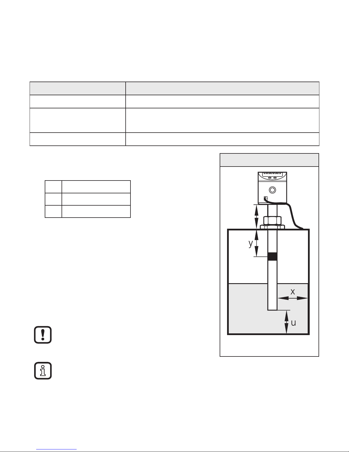
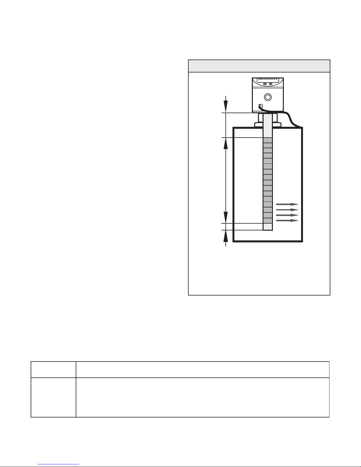
4.1 Example configuration 1
Unit LK8122 (probe length L= 264 mm)
Medium to be detected Mineral oil
Operating mode Manual media selection with overflow prevention
(Factory setting) → 5.2.1
Installation environment Metal tank, installation to Fig. 4-1
► Install unit.
► Observe the distances (x), (u) and (c):
x min. 4.0 cm
u min. 1.0 cm
c max. 14.0 cm
Fig. 4-1
OP
c
► Ground sensor and tank via an electrical
connection (→ 7).
► Observe the parameter setting sequence:
- [MEdI] = [OIL.2] (→ 10.2.3)
- [OFS] = (u); e. g. (u) = 2.0 cm (→ 5.2.4)
- [OP]: Set the overflow prevention OP at a
distance (y) greater than 4.5 cm below the
mounting element.
For distances (y) smaller than 4.5 cm there
may be malfunctioning and error messages
during the adjustment process [cOP].
Step increment and setting range: (→ 12.1).
Calculation aids for [OP]: (→ 12.3).
► Adjustment of the overflow prevention OP to [cOP] (→ 10.2.5).
> The unit is ready for operation.
► Make further settings if necessary.
► Check whether the unit operates correctly.
7
UK
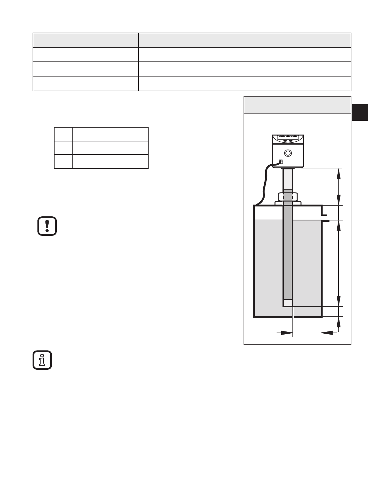
4.2 Example configuration 2
Unit LK8123 (probe length L= 472 mm)
Medium to be detected Coolant emulsion
Operating mode Automatic medium detection (→ 5.2.1)
Installation environment Metal tank, installation to Fig. 4-2
► Install unit.
► Observe the distances (x), (u) and (c):
x min. 4.0 cm
u min. 1.0 cm
c max. 23.0 cm
► Ground sensor and tank via an electrical
connection (→ 7).
► Observe the maximum permitted level (b).
A distance (a2) greater than 5.0 cm must be
observed between maximum level (b) and
mounting element.
► Observe the parameter setting sequence:
- [MEdI] = [Auto] (→ 10.2.3)
- [OFS] = (u); e. g. (u) = 1.0 cm (→ 5.2.4)
- [SP1] = Set the switch point at a distance (a2)
Fig. 4-2
c
bu a2
x
Adjustable step increment: 0.5 cm.
Switch point [SP1] is used as overflow prevention (pump off, close inlet,
...).
► Unit must be reinitialised:
► Switch the operating voltage off and on again.
> The unit is ready for operation.
► Make further settings if necessary.
► Check whether the unit operates correctly.
8
5 Function
5.1 Measuring principle
The sensor determines the level according to the capacitive measuring principle:
• An electrical field [E] is generated
and influenced by the medium to be
detected. This change to the field
causes a measurement signal that
is electronically evaluated.
• The dielectric constant of a medium
is important for its detection. Media
with a high dielectric constant
(e.g. water) generate a strong
measurement signal, media with a
low dielectric constant (e.g. oils) a
correspondingly lower signal.
• The active measurement zone of
the sensor probe is composed of
16 capacitive measuring segments.
They generate measurement
signals depending on the degree of
coverage.
Fig. 5-1
A II
E
I: Inactive zone
A: Active zone (16 active segments)
E: Electrical field
Dimensions → Technical data sheet
5.2 Operating principle / features of the unit
The unit can be installed in tanks of different sizes. Observe the notes on
installation.
4 outputs are available. They can be set separately.
OUT1 Switching signal for level limit value / IO-Link
OUT2
OUT3
OUT4
Switching signal for level limit value
To adjust the unit to the application, it provides the following operating modes:

9
UK
5.2.1 Operating modes
1. Manual media selection with overflow prevention (factory setting)
Recommended. Highest operational reliability
The medium to be detected is set manually [MEdI]. In addition, an integrated,
independently functioning overflow prevention is available.
2. Manual media selection without overflow prevention
Medium operational reliability
The medium to be detected is set manually as described under 1. However,
the overflow prevention is deactivated. For this reason, no adjustment is
required.
3. Automatic medium detection
Lowest operational reliability
Each time the operating voltage is switched on, the unit adjusts itself to the
medium and the installation environment.
For automatic media detection, no overflow prevention is available.
Automatic media detection can only function properly under certain
conditions (e.g. compliance with special mounting specifications,
restrictions for operation and maintenance).
5.2.2 Notes on the integrated overflow prevention
With the parameter [OP] (OP = overflow prevention), one of the upper measuring
segments is defined as integrated overflow prevention.
• If the overflow prevention OP is activated, an adjustment to the installation
situation has to be made [cOP].
• The overflow prevention OP can be deactivated ([OP] = [OFF]).
Deactivating the overflow prevention OP can impair the operational
reliability. For optimum operation and maximum operational reliability, we
therefore recommend to not deactivate the overflow prevention OP.
• The overflow prevention OP is the maximum limit of the measuring range. The
switch points [SPx] / [FHx] are always below [OP].
• The overflow prevention OP is not assigned to a separate output. It offers
additional protection and only switches if, as the level rises, the switching

10
output has not switched even though the corresponding switch point has been
exceeded (e.g. due to application-related malfunctions).
• Typically the overflow prevention OP reacts when the selected measuring
segment has been reached (a few mm before the set OP value).
• The overflow prevention OP replies immediately and without delay. The set
delay times (e.g. of a switch point directly below) have no effect on the overflow
prevention OP.
• The response of the overflow prevention OP is indicated on the display ("Full"
and indication of the current level change every second).
5.2.3 Display and switching functions
The unit displays the current level, selectable in cm or inches. The set unit of
measurement and the switching status of the outputs are indicated by LEDs.
The unit signals via four switching outputs (OUT1...OUT4) that a set limit has
been exceeded or that the level is below the limit. The parameters of the switching
outputs can be set.
• Hysteresis function / normally open (Fig. 5-2): [oux] = [Hno].
• Hysteresis function / normally closed (Fig. 5-2): [oux] = [Hnc].
First the set point [SPx] is set, then the reset point [rPx] with the requested
difference.
The hysteresis for the overflow prevention OP is fixed.
• Window function / normally open (Fig. 5-3): [oux] = [Fno].
• Window function / normally closed (Fig. 5-3): [oux] = [Fnc].
The width of the window can be set by means of the difference between
[FHx] and [FLx]. [FHx] = upper value, [FLx] = lower value.

11
UK
Fig. 5-2 Fig. 5-3
SP
rP
t
L
FH
FL
1
0
1
0
FE
Fno
Fnc
L: Level HY: Hysteresis FE: Window
5.2.4 Offset for indicating the real level in the tank
The distance between tank bottom and lower edge of the probe can be entered as
offset value [OFS]. So display and switch points refer to the actual level (point of
reference = tank bottom).
For [OFS] = [0]: The reference point is the lower edge of the measuring
probe.
The set offset only refers to the display on the unit. It has no effect on
the process value transmitted via IO-Link. The OFS parameter, however,
is correctly transmitted via IO-Link and can therefore be taken into
consideration. More information → 5.2.6.
5.2.5 Defined state in case of a fault
In case of a fault a state can be defined for each output. If a fault is detected or if
the signal quality is below a minimum value, the outputs pass into a defined state.
For this case the response of the outputs can be set via the parameters
[FOU1]...[FOU4] (→ 10.3.7).
5.2.6 IO-Link function
This unit has an IO-Link communication interface which requires an IO-Linkcapable module (IO-Link master) for operation.
The IO-Link interface enables direct access to the process and diagnostic data
and provides the possibility to set the parameters of the unit during operation.

12
In addition communication is possible via a point-to-point connection with a USB
adapter cable.
The IODDs necessary for the configuration of the unit, detailed information about
process data structure, diagnostic information, parameter addresses and the
necessary information about the required IO-Link hardware and software can be
found at www.ifm.com.
 Loading...