

Page 1

Device manual
Inclination sensor
2 axes
JN2300
UK
80228165/00 04/2015
Page 2

Inclination sensor JN
Contents
1 Preliminary note � � � � � � � � � � � � � � � � � � � � � � � � � � � � � � � � � � � � � � � � � � � � � � � � � 4
1�1 Symbols used� � � � � � � � � � � � � � � � � � � � � � � � � � � � � � � � � � � � � � � � � � � � � � � 4
2 Safety instructions � � � � � � � � � � � � � � � � � � � � � � � � � � � � � � � � � � � � � � � � � � � � � � � 4
2�1 General� � � � � � � � � � � � � � � � � � � � � � � � � � � � � � � � � � � � � � � � � � � � � � � � � � � � 4
2�2 Target group � � � � � � � � � � � � � � � � � � � � � � � � � � � � � � � � � � � � � � � � � � � � � � � � 4
2�3 Electrical connection � � � � � � � � � � � � � � � � � � � � � � � � � � � � � � � � � � � � � � � � � 4
2�4 Tampering with the device � � � � � � � � � � � � � � � � � � � � � � � � � � � � � � � � � � � � � 5
3 Functions and features � � � � � � � � � � � � � � � � � � � � � � � � � � � � � � � � � � � � � � � � � � � � 5
4 Installation � � � � � � � � � � � � � � � � � � � � � � � � � � � � � � � � � � � � � � � � � � � � � � � � � � � � � 5
4�1 Fixing � � � � � � � � � � � � � � � � � � � � � � � � � � � � � � � � � � � � � � � � � � � � � � � � � � � � � 5
4�2 Mounting surface � � � � � � � � � � � � � � � � � � � � � � � � � � � � � � � � � � � � � � � � � � � � 5
5 Scale drawing � � � � � � � � � � � � � � � � � � � � � � � � � � � � � � � � � � � � � � � � � � � � � � � � � � � 6
6 Electrical connection� � � � � � � � � � � � � � � � � � � � � � � � � � � � � � � � � � � � � � � � � � � � � � 6
6�1 Bus termination � � � � � � � � � � � � � � � � � � � � � � � � � � � � � � � � � � � � � � � � � � � � � 6
7 SAE J1939 interface� � � � � � � � � � � � � � � � � � � � � � � � � � � � � � � � � � � � � � � � � � � � � � 7
7�1 Overview and structure of the SAE J1939 protocol � � � � � � � � � � � � � � � � � � 7
7�1�1 PDU format 1 � � � � � � � � � � � � � � � � � � � � � � � � � � � � � � � � � � � � � � � � � � � 7
7�1�2 PDU format 2 � � � � � � � � � � � � � � � � � � � � � � � � � � � � � � � � � � � � � � � � � � � 7
7�2 Proprietary PDU format 1 protocol � � � � � � � � � � � � � � � � � � � � � � � � � � � � � � � 8
7�3 Configuration examples � � � � � � � � � � � � � � � � � � � � � � � � � � � � � � � � � � � � � � � 9
7�4 Proprietary PDU format 2 messages � � � � � � � � � � � � � � � � � � � � � � � � � � � � � 9
7�5 Configuration examples � � � � � � � � � � � � � � � � � � � � � � � � � � � � � � � � � � � � � � 10
8 Parameter mapping � � � � � � � � � � � � � � � � � � � � � � � � � � � � � � � � � � � � � � � � � � � � � �11
8�1 Communication profile proprietary (0x500 – 0x1303) � � � � � � � � � � � � � � � �11
8�2 System settings 0x2000 - 0x207F)� � � � � � � � � � � � � � � � � � � � � � � � � � � � � � 13
8�2�1 Informative (0x2080 – 0x2082) � � � � � � � � � � � � � � � � � � � � � � � � � � � � 15
8�2�2 Upload/download (0x3000) � � � � � � � � � � � � � � � � � � � � � � � � � � � � � � � 15
8�2�3 Measured data (0xA000 – 0xA011) � � � � � � � � � � � � � � � � � � � � � � � � � 15
8�2�4 Additional functionality (0xA100���0xA202)� � � � � � � � � � � � � � � � � � � � 15
9 Angle definition (0x2044) � � � � � � � � � � � � � � � � � � � � � � � � � � � � � � � � � � � � � � � � � 16
9�1 Perpendicular angle (0x2044 = 0) � � � � � � � � � � � � � � � � � � � � � � � � � � � � � � 16
9�2 Euler angle (0x2044 = 1) � � � � � � � � � � � � � � � � � � � � � � � � � � � � � � � � � � � � � 16
9�3 Gimbal angle X (0x2044 = 2) � � � � � � � � � � � � � � � � � � � � � � � � � � � � � � � � � � 17
9�4 Gimbal angle Y (0x2044 = 3) � � � � � � � � � � � � � � � � � � � � � � � � � � � � � � � � � � 17
9�5 Explanatory example � � � � � � � � � � � � � � � � � � � � � � � � � � � � � � � � � � � � � � � � 18
10 Other sensor functions � � � � � � � � � � � � � � � � � � � � � � � � � � � � � � � � � � � � � � � � � � 18
10�1 Device address (0x2000) and baud rate (0x2001) � � � � � � � � � � � � � � � � � 18
10�2 Limit frequency digital filter (0x2043) � � � � � � � � � � � � � � � � � � � � � � � � � � � 18
10�3 Set zero point (0x2046) � � � � � � � � � � � � � � � � � � � � � � � � � � � � � � � � � � � � � 19
10�4 Terminating resistor (0x2045)� � � � � � � � � � � � � � � � � � � � � � � � � � � � � � � � � 19
2
Page 3

Inclination sensor JN
10�5 Set teach (0x2042h) � � � � � � � � � � � � � � � � � � � � � � � � � � � � � � � � � � � � � � � � 19
10�6 Quadrant correction (0x2040) � � � � � � � � � � � � � � � � � � � � � � � � � � � � � � � � 20
10�7 Heating (0x2041h) � � � � � � � � � � � � � � � � � � � � � � � � � � � � � � � � � � � � � � � � � 20
10�8 MEMS measuring cell temperature (0x2081)� � � � � � � � � � � � � � � � � � � � � 21
10�9 MEMS self-test (0x4008 / 0x4009) � � � � � � � � � � � � � � � � � � � � � � � � � � � � � 21
10�10 Programming key (0x3000) � � � � � � � � � � � � � � � � � � � � � � � � � � � � � � � � � 21
11 Status LED � � � � � � � � � � � � � � � � � � � � � � � � � � � � � � � � � � � � � � � � � � � � � � � � � � � 22
12 Maintenance, repair and disposal� � � � � � � � � � � � � � � � � � � � � � � � � � � � � � � � � � 22
13 Approvals/standards � � � � � � � � � � � � � � � � � � � � � � � � � � � � � � � � � � � � � � � � � � � � 22
14 Factory setting � � � � � � � � � � � � � � � � � � � � � � � � � � � � � � � � � � � � � � � � � � � � � � � � 22
UK
This document is the original instructions�
3
Page 4

Inclination sensor JN
1 Preliminary note
This document applies to the device of type "inclination sensor" (art� no�: JN2300)�
It is part of the device�
This document is intended for specialists� These specialists are people who are
qualified by their appropriate training and their experience to see risks and to
avoid possible hazards that may be caused during operation or maintenance of
the device� The document contains information about the correct handling of the
device�
Read this document before use to familiarise yourself with operating conditions,
installation and operation� Keep this document during the entire duration of use of
the device�
Adhere to the safety instructions�
1.1 Symbols used
► Instructions
> Reaction, result
[…] Designation of keys, buttons or indications
→ Cross-reference
Important note
Non-compliance may result in malfunction or interference�
Information
Supplementary note
2 Safety instructions
2.1 General
These instructions are an integral part of the device� They contain texts and figures
concerning the correct handling of the device and must be read before installation
or use�
Observe the operating instructions� Non-observance of the instructions, operation
which is not in accordance with use as prescribed below, wrong installation or
incorrect handling can seriously affect the safety of operators and machinery�
2.2 Target group
These instructions are intended for authorised persons according to the EMC and
low-voltage directives� The device must only be installed, connected and put into
operation by a qualified electrician�
2.3 Electrical connection
Disconnect the unit externally before handling it�
4
Page 5

Inclination sensor JN
The connection terminals may only be supplied with the signals indicated in the
technical data and/or on the device label and only the approved accessories from
ifm may be connected�
2.4 Tampering with the device
Contact the manufacturer in case of malfunction of the unit or uncertainties�
Any tampering with the device can seriously affect the safety of operators and
machinery� In case of tampering with and/or modifying the unit, any liability and
warranty is excluded�
3 Functions and features
The 2-axis inclination sensor with SAE J1939 interface enables angle levelling and
position detection of mobile machines�
Typical applications are, for example, the position detection of access platforms,
levelling of mobile cranes or set-up of mobile machines�
UK
Properties:
● 2-axis inclination sensors with a measuring range of ±180° (0���360°)
● High accuracy and resolution
● High sampling rate and band width
● Diagnostic Trouble Code (DTC) available
● Configurable limit frequency (digital filter) for vibration suppression
● Programming key
4 Installation
4.1 Fixing
► Fasten the device using 4 M5 screws on a flat surface�
Screw material: steel or stainless steel�
4.2 Mounting surface
The housing must not be exposed to any torsional forces or mechanical
stress�
► Use compensating elements if there is no flat mounting surface available�
5
Page 6
Inclination sensor JN
21
12
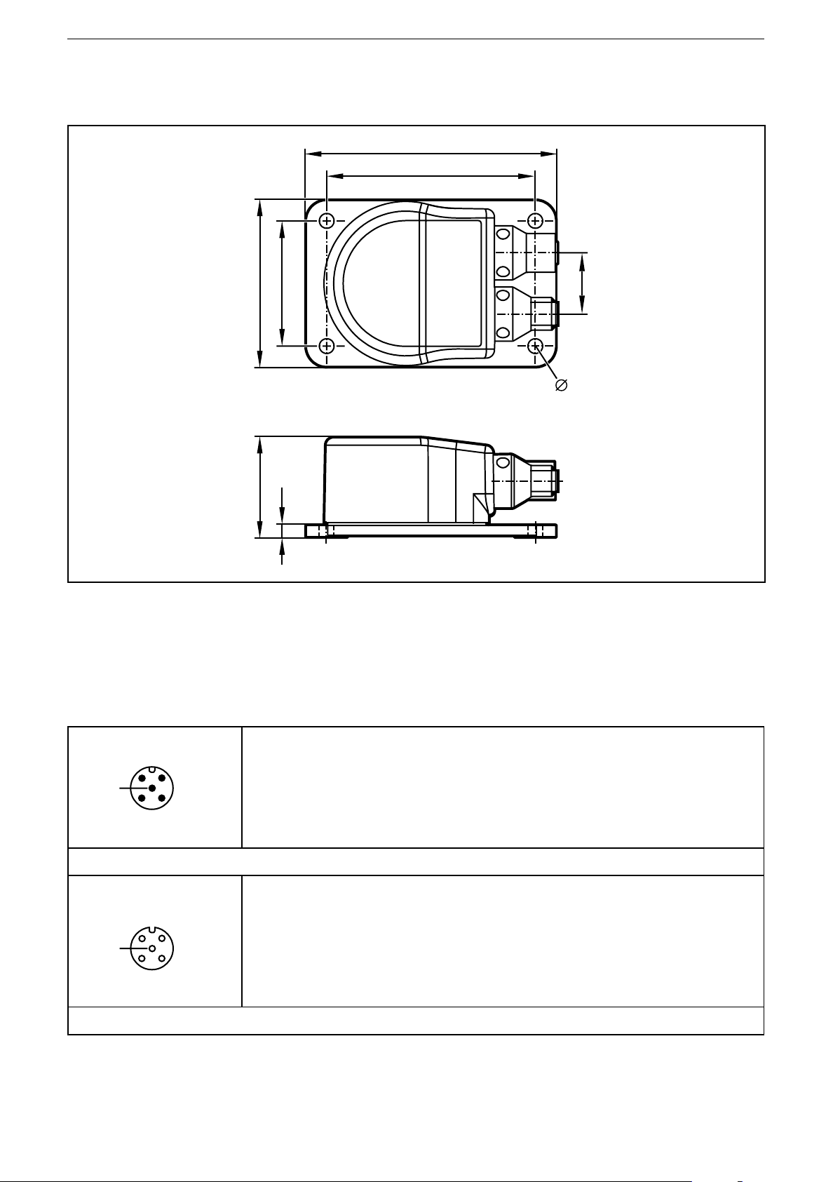
5 Scale drawing
90
75
60
36
45
4,5
22
5,3
6 Electrical connection
The inclination sensors are fitted with two round 5-pole M12 connectors (A-coded)�
The pin configuration is as illustrated�
1: CAN_SHLD CAN shield
2: CAN_V+ Supply voltage 24 V DC (+UB)
5
3
M12 connector CAN-In
4
5
4
M12 socket CAN-Out
3
3: CAN_GND Ground
4: CAN_H High bus cable
5: CAN_L Low bus cable
1: CAN_SHLD CAN shield
2: CAN_V+ Supply voltage 24 V DC (+UB)
3: CAN_GND Ground
4: CAN_H High bus cable
5: CAN_L Low bus cable
6.1 Bus termination
The inclination sensors have an internal 120 Ohm terminating resistor that can be
assigned (index 0x2045)�
6
Page 7

Inclination sensor JN
7 SAE J1939 interface
The inclination sensors have a standardised SAEJ1939 interface� All measured
values and parameter groups can be accessed via the J1939 protocol� The
individual configuration can be saved in the internal permanent memory (flash)�
7.1 Overview and structure of the SAE J1939 protocol
SAE J1939 uses 29-bit CAN identifier (extended frame format CAN 2�0B)� An SAE
J1939 message has the following structure:
SAE J1939 message
29-bit CAN identifier Data
Priority
28…26
Parameter Group Number (PGN)
Ext� data page 25 Data page 24 PDU format (PF)
PGN
25���8
Source address
7���0
23…16
PDU format 1 (specific)
00h - EFh
23…16
PDU format 2 (global)
User data of the
message
0…8 bytes
Target address / group
extension (PS) 15…8
Target address (DA)
15…8
UK
F0h - FFh
23…16
Group Extension (GE)
15…8
7.1.1 PDU format 1
This format defines a message which is sent to a defined unit� In this case the
PDU-specific byte (PS) is the target address (DA) of the unit� If the value of the
PDU format field (PF) is between 0x00 and 0xEF, it is a PDU format 1 message�
For proprietary (manufacturer-specific) messages the PDU format value 0xEF is
defined� Ext� data page bit = 0 and data page bit = 0�
7.1.2 PDU format 2
This format defines a message which is sent globally� In this case the PDUspecific byte (PS) corresponds to the group extension (GE)� If the value of the
PDU format field (PF) is between 0xF0 and 0xFF, it is a PDU format 1 message�
For proprietary (manufacturer-specific) messages the area (PDU format PF) and
group extension (GE) 0xFF00 – 0xFFFF is defined�
Ext� data page bit = 0 and data page bit = 0
7
Page 8

Inclination sensor JN
7.2 Proprietary PDU format 1 protocol
The parameters of the JN2300 sensors are listed in a table that is accessed per
16-bit index� To access the sensor parameters in reading or writing the proprietary
PDU format 1 message is used� PDU format (PF) corresponds to the value 0xEF�
In this case the PDU-specific byte (PS) is the target address (DA) of the unit which
the message is to be sent to�
Example
Address target unit (ECU): 0x19
Address control unit / master: 0x14
Priority of the message: 3
CAN identifier 8-byte data frame
ID 29 bits Parameter index 2 bytes Read/write 1 byte Status 1 byte 4-byte data
Request: Master → ECU
0xCEF1914 LSB MSB RW 0 LSB �� �� MSB
Answer: Master ← ECU
0xCEF1419 Index RW SC LSB �� �� MSB MSB
Parameter index: 2-byte parameter index�
RW: Read parameter → 0x00 / write parameter → 0x01
SC: Status code
0x00: OK
0x01: parameter value too small
0x02: parameter value too big
0x03: parameter index does not exist
0x04: parameter can only be read
0x05: parameter can only be written
0x06: no access to parameter
0x07: invalid data size
0x08: parameter writing blocked (e�g�: If the same value of a parameter is written
which is already set in the sensor)
0x09: invalid command
0x0A: unknown error�
8
Page 9

7.3 Configuration examples
Address target unit (ECU): 0x19
Address control unit / master: 0x14
Priority of the message: 3
Inclination sensor JN
Example: Set FIR filter for angle measurement to lowpass 5 Hz, index 0x2043/2
Master → ECU
CAN identifier 8-byte data frame
0xCEF1914 0x43 0x20 0x01 0x00 0x02 0x00 0x00 0x00
Response master ← ECU, status code: OK
0xCEF1419 0x43 0x20 0x01 0x00 0x02 0x00 0x00 0x00
Example: Read FIR filter for angle measurement, index 0x2043
Master → ECU
CAN identifier 8-byte data frame
0xCEF1914 0x43 0x20 0x00 0x00 0x00 0x00 0x00 0x00
UK
Response master ← ECU, status code: OK
0xCEF1419 0x43 0x20 0x00 0x00 0x02 0x00 0x00 0x00
7.4 Proprietary PDU format 2 messages
The measured data of the JN2300 sensor is sent cyclically via proprietary PDU
format 2 messages� PDU format (PF) corresponds to the value 0xFF� In this case
the PDU-specific byte (PS) is the group extension (GE); it can be freely set by the
user in the range 0x00 – 0xFF�
In the following these parameter groups are called transmit PGNs (TxPGNs)�
JN2300 supports four TxPGNs:
TxPGN0
2-byte angle information longitudinal X, 2-byte angle information lateral Y
TxPGN1
4-byte angle information longitudinal X, 4-byte angle information lateral Y
9
Page 10

Inclination sensor JN
TxPGN2
4-byte V_effective , 4-byte aPeak
TxPGN3
2-byte acceleration X, 2-byte acceleration Y, 2-byte acceleration Z
7.5 Configuration examples
For the examples:
Address JN2300 (ECU): 0x19, priority: 1
TxPGN0 default group extension (GS): 0x00
X: Angle value longitudinal X
y: Angle value lateral Y
CAN identifier 8-byte data frame
0x4FF0019 LSB (X) MSB
(X)
LSB (Y) MSB
(Y)
TxPGN1 default group extension (GS): 0x01
X: Angle value longitudinal X
Y: Angle value lateral Y
CAN identifier 8-byte data frame
0x4FF0119 LSB (X) �� �� MSB
(X)
LSB (Y) �� �� MSB (Y)
TxPGN2 default group extension (GS): 0x02
V: v effective
A: a peak
CAN identifier 8-byte data frame
- - - -
0x4FF0219 LSB (v) �� �� MSB (v) LSB (a) �� �� MSB (a)
TxPGN3 default group extension (GS): 0x03
X: acceleration X axis
Y: acceleration Y axis
Z: acceleration Z axis
CAN identifier 8-byte data frame
0x4FF0319 LSB (X) MSB
(X)
10
LSB (Y) MSB
(Y)
LSB (z) MSB (z) - -
Page 11

Inclination sensor JN
8 Parameter mapping
8.1 Communication profile proprietary (0x500 – 0x1303)
Index Type Value Unit R/W Reset
0x500 ASCII Device name R
0x501 ASCII Software version R
0x4003 UNSIGNED32 Serial number R
UK
0x1000 UNSIGNED8 Transmit parameter groups
number 0 active�
TxPGN0
2-byte angle longitudinal X
2-byte angle lateral X
0: is not sent cyclically
1: is sent cyclically
0x1001 UNSIGNED8 1 byte TxPGN0 LSB
PGN0: 0xFFXX
default: 0xFF00
0x1002 UNSIGNED16 TxPGN0 cycle time
default: 15 ms
min� 15 ms, max� 50000 ms
0x1003 UNSIGNED8 TxPGN0 priority
default: 1
min� 0 / max 7
R/W
R/W X
ms R/W X
R/W X
0x1100 UNSIGNED8 Transmit parameter groups
number 1 active�
TxPGN1
4-byte angle longitudinal X
4-byte angle lateral Y
0: is not sent cyclically
1: is sent cyclically
0x1101 UNSIGNED8 1 byte TxPGN1 LSB
PGN1: FFXX
default: 0xFF01
0x1102 UNSIGNED16 TxPGN1 cycle time
default: 15 ms
min� 15 ms, max� 50000 ms
0x1103 UNSIGNED8 TxPGN1 priority
default: 1
min� 0 / max� 7
R/W
R/W X
R/W X
R/W X
11
Page 12

Inclination sensor JN
Index Type Value Unit R/W Reset
0x1200 UNSIGNED8 Transmit parameter groups
number 2 active
TxPGN2
4 bytes v eff
4 bytes a peak
0: is not sent cyclically
1: is sent cyclically
0x1201 UNSIGNED8 1 byte TxPGN2 LSB
PGN2: FFXX
default: 0xFF02
0x1202 UNSIGNED16 TxPGN2 cycle time
Default: 25 ms
min� 25 ms, max� 50000 ms
0x1203 UNSIGNED8 TxPGN2 priority
default: 1
R/W
R/W X
ms R/W X
R/W X
min� 0 / max� 7
0x1300 UNSIGNED8 Transmit parameter groups
number 3 active�
TxPGN3
2-byte acceleration X axis
2-byte acceleration Y axis
2-byte acceleration Z axis
0: is not sent cyclically
1: is sent cyclically
0x1301 UNSIGNED8 1 byte TxPGN3 LSB
PGN3: FFXX
default: 0xFF03
0x1302 UNSIGNED16 TxPGN3 cycle time
default: 5 ms
R/W
R/W X
ms R/W X
min� 5 ms, max� 50000 ms
0x1303 UNSIGNED8 TxPGN3 priority
default: 1
min� 0 / max� 7
12
R/W X
Page 13

Inclination sensor JN
8.2 System settings 0x2000 - 0x207F)
Index Type Value Unit R/W Reset
0x2000 UNSIGNED8 Device address
default 25
0x2001 UNSIGNED16 Baud rate
default 250
0x2002 UNSIGNED8 Flag to reset MC
→
flag = 1
0x2040 UNSIGNED8 Flag for quadrant correction
0: off
1: on
2: on
0x2041 UNSIGNED8 Flag for heating
flag = 0
flag = 1
0x2042 UNSIGNED8 Index for teach values
of the X/Y/Z axes
0: no change
1: set teach, relative
measurement
2: reset teach, absolute
measurement
MC reset
→
± 180°
→
0° - 360°
→
heating off
→
heating on
R/W X
Kbit R X
R/W
R/W
R/W
R/W
UK
0x2043 UNSIGNED8 FIR filter step for angle
measurement
0 : FIR deactivated
1 : FIR lowpass 10Hz
2 : FIR lowpass 5Hz
3 : FIR lowpass 1Hz
4 : FIR lowpass 0�5Hz
0x2044 UNSIGNED8 Angle calculation
0: perpendicular
1: Euler
2: gimbal 1X
3: gimbal 1Y
0x2045 UNSIGNED8 CAN 120 Ohm terminating
resistor
0: resistor deactivated
1: resistor activated
R/W
R/W
R/W
13
Page 14

Inclination sensor JN
Index Type Value Unit R/W Reset
0x2046 UNSIGNED8 Set index for zero of the
X / Y / Z axes
0: no change
1: activate set zero; relative
measurement
2: reset set zero; absolute
measurement
0x2047 UNSIGNED8 Output value
0: angle
1: v eff (v effective) and a peak
(a peak)
2: aVector X / Y / Z
without DC part
3: aVector X / Y / Z
with DC part
→
automatic selection of
measuring range ± 2 g
0x2048 UNSIGNED8 Axis selection
v eff / a peak
R/W
R/W
R/W
X axis active
X axis not active
Y axis active
Y axis not active
Z axis active
Z axis not active
0x2049 UNSIGNED8 FIR filter step for
v eff / a peak measurement
0 : FIR deactivated
1 : FIR bandpass filter 0�1���1
Hz
2 : FIR bandpass filter 0�1���10
Hz
3 : FIR bandpass filter 1���10 Hz
4 : FIR bandpass filter 2���400
Hz
5 : FIR bandpass filter 10���400
Hz
→
bit 2 = 1
→
→
bit 1 = 1
→
→
bit 0 = 1
→
bit 2 = 0
bit 1 = 0
bit 0 = 0
R/W
0x204A UNSIGNED8 Measuring range for v eff /
a peak measurement and
acceleration
0: ± 2 g
1: ± 4 g
2: ± 8 g
14
R/W
Page 15

Inclination sensor JN
Index Type Value Unit R/W Reset
0x207F UNSIGNED8 Factory reset
1: make factory reset
R/W
8.2.1 Informative (0x2080 – 0x2082)
Index Type Value Unit R/W Reset
0x2080 INTEGER16 Ambient temperature 1/10 °C R
0x2081 INTEGER16 MEMS temperature 1/10 °C R
0x2082 UNSIGNED16 Heating power mW R
8.2.2 Upload/download (0x3000)
0x3000 ASCII Programming key R/W
8.2.3 Measured data (0xA000 – 0xA011)
UK
0xA000 INTEGER16 Longitudinal X axis ° R
0xA001 INTEGER16 Lateral Y axis ° R
0xA010 INTEGER32 Longitudinal X axis ° R
0XA011 INTEGER32 Lateral Y axis ° R
8.2.4 Additional functionality (0xA100...0xA202)
0xA100 UNSIGNED32 v effective vector 1/10 mm/s R
0xA101 UNSIGNED32 a peak vector mg R
0xA200 INTEGER16 aVector X axis mg R
0xA201 INTEGER16 aVector Y axis mg R
0XA202 INTEGER16 aVector Z axis mg R
15
Page 16

Inclination sensor JN
9 Angle definition (0x2044)
To be able to adapt the inclination sensor to the different applications as easily
as possible, the measured inclination information is converted into different angle
indications� The requested angle indication is set by selecting the respective
option�
With this angle definition a sensor coordinate system is used which is defined as
follows:
– The mounting plane corresponds to the XY plane�
– The Z axis is perpendicular to the mounting plane (according to the right-
hand rule)�
– The X axis is represented by an edge of the mounting plate which shows in
direction of the printed X arrow�
– The Y axis is then perpendicular to the plane spanned by the Z and X axes�
9.1 Perpendicular angle (0x2044 = 0)
Using the indication of the two perpendicular angles the inclination of the sensor
coordinate system towards the direction of gravitation is described�
The first provided value corresponds to a rotation about the Y axis of the sensor
and is called "longitudinal inclination value"�
The value corresponds to the angle [°] which the gravitation vector spans with the
YZ plane�
The second provided value corresponds to a rotation about the X axis of the
sensor and is called "lateral inclination value" (SDO index 6020h or 6120h)� The
value corresponds to the angle [°] between the gravitation vector and the XZ plane
of the sensor�
In the case of an inclination in a plane (rotation of an axis with the second axis remaining
perpendicular) the perpendicular angle and gimbal angle are always identical�
9.2 Euler angle (0x2044 = 1)
In this setting the two provided angle values are to be interpreted as Euler angle�
The current sensor orientation is determined by two successive rotations from the
horizontal position�
The "inclination value longitudinal" indicates the angle [°] at which the Z axis of
the sensor is inclined� The "inclination value lateral" corresponds to the angle [°] at
which the sensor was then rotated about the (inclined) Z axis�
Interpretation
The first angle value corresponds to the angle between the gravitation vector and
the sensor's Z axis (slope inclination, gradient angle) whereas the second angle
value indicates the direction in which the slope inclination matches the coordinate
system�
16
Page 17

Inclination sensor JN
Value range for this option
– Inclination value longitudinal (gradient angle): -90°…+90°
– Inclination value lateral (angle of direction): 0°…360°
Critical point
With a gradient angle of 0° the sensor is in a horizontal position� In this position the
second angle (angle of direction) is useless� In practice, it is to be expected that
the value of the second angle will vary very strongly even if the sensor is virtually
motionless�
9.3 Gimbal angle X (0x2044 = 2)
As with the Euler angle the current orientation of the sensor is described by two
successive rotations from the horizontal position�
But the current orientation now arises from a rotation about the Y axis with the
angle value [°] indicated by the "inclination value longitudinal" as well as from
a rotation which then follows about the (now rotated) X axis with the angle [°]
"inclination value lateral"�
UK
Interpretation
If you imagine the sensor as a plane whose body shows in X direction and
whose wings in Y direction, the "inclination value longitudinal" corresponds to the
longitudinal inclination of the plane (pitch angle) and the "inclination value lateral"
to the bank angle (roll angle) of the plane�
Value range
– Inclination value longitudinal: -90°…90°
– Inclination value lateral: -180°…180°
Critical point
With a longitudinal inclination of ± 90° ("plane" flies vertically downwards or
upwards) the roll angle makes a rotation about the gravitational axis which cannot
be detected by the inclination sensor� In this condition the "inclination value lateral"
is insignificant� In practice, the "inclination value lateral" will vary very strongly
when it is close to this condition even if there is only little movement�
9.4 Gimbal angle Y (0x2044 = 3)
This setting corresponds to the setting described in 8�3 with the difference that the
order of the two rotations is now inverted� In this option the measured object is first
rotated about its X axis with the angle [°] "inclination value lateral"� The measured
object is then rotated about the Y axis (which is now inclined) with the angle value
[°] indicated by the "inclination value longitudinal" of the sensor�
As a result of this the measured values of the gimbal angle X and the gimbal angle
Y are identical as long as the measured object is only rotated about one of the
sensor's axes� The measured values of the two options do not differ until a general
rotation is made about the two sensitivity axes�
17
Page 18

Inclination sensor JN
1
2
3
4
5
6
9.5 Explanatory example
The different angle definitions will be illustrated using a simple example� An
excavator moves up and down an embankment (illustration)� The embankment is
angled at 30°� The inclination sensor is installed so that the positive Y axis of the
sensor shows in driving direction of the excavator�
Excavator
position
1 0° 0° 0°
2 0° -30° 30° 0° 0° -30° 0° -30°
3 20° -20° 30° 45° 20° -22° 22° -20°
4 30° 0° 30° 90° 30° 0° 30° 0°
5 30° 0° 30° 90° 30° 0° 30° 0°
6 0° 30° 30° 180° 0° 30° 0° 30°
Perpendicular angle Euler Gimbal X Gimbal Y
Longitudinal Lateral Longitudinal Lateral Longitudinal Lateral Longitudinal Lateral
Undefined
0° 0° 0° 0°
10 Other sensor functions
10.1 Device address (0x2000) and baud rate (0x2001)
In the case of a change the device address and baud rate do not become effective
until after a reset (reset application, reset communication or hardware reset)�
The inclination sensor from ifm is delivered with the device address 25 and a baud rate of 250
Kbits/s�
10.2 Limit frequency digital filter (0x2043)
With the sensor it is possible to make continuously arising angle values insensitive
to external interfering vibrations�
Using a configurable filter (digital FIR filter) interfering vibrations can be
suppressed� The limit frequency of the filter is set via the FIR filter step (index
2043h)�
18
Page 19

Inclination sensor JN
10.3 Set zero point (0x2046)
To set the zero point the sensor is rotated to the requested position and the current
position is set as "0"� The value of the parameter "set zero point X and Y axes"
(index 2046h) is to be set to 1�
The sensor then calculates the offset to the zero point shift and saves it in the
permanent memory� From then on the offset is subtracted from the angle�
10.4 Terminating resistor (0x2045)
In bus topology a system is terminated with terminating resistors (120 Ω) at the
beginning and end� If the sensor is at the beginning or end, the terminating resistor
(index 2045h) integrated in the sensor can be activated by writing the value 1�
10.5 Set teach (0x2042h)
UK
Should it not be possible to integrate the inclination sensor into the measured
object so that the coordinate system of the sensor and object coordinate system
match, the teach function enables the creation of a new reference system�
The new reference system Xb,Yb, Zb is defined so that its Zb direction corresponds
to the direction of gravitation at the teach moment� The Xb direction of the
reference system results from the projection of the Xs axis of the sensor to the XbYb
plane of the reference system� The Yb axis then corresponds to the direction which
is perpendicular to both the Zb and the Xb axis�
The result of this is that at the teach moment the X
gravitation� As long as the value for the index 2042h is 1, all angle indications are converted into the
new reference system�
axis must not be parallel to the direction of
S
The teach operation can, for example, be as follows:
The measured object with the non-aligned inclination sensor is brought into a
known horizontal position� In this position the teach function is carried out, thus
defining the new reference system� All provided angle values then refer to this new
reference system�
Even with an inclination sensor which is installed at an angle note that the X axis (X
sensor is parallel to the XbZb plane of the requested reference system�
axis) of the
S
19
Page 20

Inclination sensor JN
Explanatory example
Inclination sensor installed at an angle in the
coordinate system of the workpiece� The coordinate
system of the sensor is transferred to the coordinate
system of the workpiece by teaching the sensor
The raw data of the sensor is indicated in the
coordinate system of the sensor�
In teach mode the data is converted into the
coordinate system of the workpiece�
when the workpiece is horizontally aligned�
The example shows a rotation of 30° about the Y axis of the coordinate system of
the workpiece�
Perpendicular angle
without teach
Longitudinal
angle value
Lateral
angle value
-13�2° -29�3° 0° 0° -45�5° -29�5° -30° 0°
Teach mode Perpendicular angle
without teach
Longitudinal
angle value
Lateral angle
value
Longitudinal
angle value
Lateral angle
value
Teach mode
Longitudinal
angle value
Lateral angle
value
10.6 Quadrant correction (0x2040)
Quadrant correction means for JN2300 only an extension of the lateral Euler
angle to the measuring ranges ± 180° (corresponds to 2040h = 1) or 0���360°
(corresponds to 2040h = 2)�
10.7 Heating (0x2041h)
To ensure good temperature stability over the whole temperature range, the
measuring cell is regulated to a constant temperature using a PID controller� The
regulation of the heating is set by the factory and can be deactivated by writing the
value 0 to the parameter of the heating (index 2041h)�
This has the following effects:
> Reduction of temperature stability
> Current consumption decreases when operating
> Accuracies deviate from the indications in the data sheet
20
Page 21

Inclination sensor JN
10.8 MEMS measuring cell temperature (0x2081)
The temperature of the measuring cell is determined every 200 ms and updated
in the protocol at "informative"� It can be read via access to the index 2081h� The
signed 16-bit value indicates the temperature in 1/10°C�
10.9 MEMS self-test (0x4008 / 0x4009)
To check the function of the measurement axes a self-test of the measuring cell
UK
can be carried out�
The MEMS self-test (index 4008/01h) has to be activated by writing the value
1� The self-test takes about 2 s; when the self-test has ended, the flag (index
4008/01h) is reset to 0� The test result is coded in a byte and can be read from the
self-test register (index 4009h)�
00000111 of the 3 least significant bits code the internal X, Y, Z measurement
axes: axis faulty / bit 1: axis functional
10.10 Programming key (0x3000)
The sensor can convert the parameter setting unambiguously into a Base64-coded
key�
By means of this key sensors with the same parameter setting can be duplicated
in an easy way�
The programming key can be read from and written to index 3000h� To ensure
that only valid keys are accepted by the firmware a 2-byte checksum (CRC) is
calculated and added to the end of the key�
The following parameters are coded by the key
Parameter Index Sub-index
Node ID 0x2000 0x00
Baud rate 0x2001 0x00
Quadrant correction 0x2040 0x00
Heating 0x2041 0x00
Teach index 0x2042 0x00
FIR filter angle 0x2043 0x00
Angle calculation 0x2044 0x00
CAN 120 Ohm resistor 0x2045 0x00
Set zero point 0x2046 0x00
Output value 0x2047 0x00
Axis selection for Veff & aPeak 0x2048 0x00
FIR filter for vibration measurement 0x2049 0x00
Measuring range vibration measurement 0x204A 0x00
21
Page 22

Inclination sensor JN
The default setting of the programming key is:
j4w+ZEgRKHAl5Y8=
11 Status LED
The integrated LED indicates the current device state�
LED colour Flashing frequency Description
Green Permanently on The device is in the "run" state
12 Maintenance, repair and disposal
The unit is maintenance-free�
► Dispose of the device in accordance with the national environmental
regulations�
13 Approvals/standards
The CE declaration of conformity and approvals can be found at:
www.ifm.com → Data sheet search → JN2300
14 Factory setting
Index Type Value Delivery
0x1000 u8 TxPGN0 active 1: is sent cyclically
0x2000 u8 Device address 25
0x2001 u16 Baud rate 250 Kbits
0x2040 u8 Flag for quadrant correction 2: corresponds to "0° ��� 360°”
0x2041 u8 Flag for heating 1: corresponds to "heating on"
0x2042 u8 Index teach value of the X/Y/Z axes 2: corresponds to "absolute measurement"
0x2043 u8 FIR filter step 2: corresponds to "FIR lowpass 5Hz"
0x2044 u8 Angle calculation 0: corresponds to "perpendicular"
0x2045 u8 CAN 120 Ω terminating resistor 1: corresponds to "activated"
0x2046 u8 Set zero point of the X/Y axes 2: corresponds to "absolute measurement"
0x2047 u8 Output value 0: corresponds to "angle"
0x2048 u8 Axis selection 7: corresponds to "X/Y/Z" activated
0x2049 u8 FIR filter for V_eff 5: corresponds to "10���400 Hz"
0x204A u8 Measuring range for V_eff / a_Peak 2: corresponds to "8g”
22
Page 23

Inclination sensor JN
UK
23
 Loading...