

Page 1
Device manual
Inclination sensor
2 axes
JN2200
Firmware 1.0
UK
80237498/00 04/2016
Page 2

Inclination sensor JN
Content
1 Preliminary note . . . . . . . . . . . . . . . . . . . . . . . . . . . . . . . . . . . . . . . . . . . . . . . . . 4
1.1 Symbols used. . . . . . . . . . . . . . . . . . . . . . . . . . . . . . . . . . . . . . . . . . . . . . . 4
2 Safety instructions . . . . . . . . . . . . . . . . . . . . . . . . . . . . . . . . . . . . . . . . . . . . . . . 4
2.1 General information . . . . . . . . . . . . . . . . . . . . . . . . . . . . . . . . . . . . . . . . . . 4
2.2 Target group . . . . . . . . . . . . . . . . . . . . . . . . . . . . . . . . . . . . . . . . . . . . . . . . 4
2.3 Electrical connection . . . . . . . . . . . . . . . . . . . . . . . . . . . . . . . . . . . . . . . . . 4
2.4 Tampering with the device . . . . . . . . . . . . . . . . . . . . . . . . . . . . . . . . . . . . . 5
3 Functions and features . . . . . . . . . . . . . . . . . . . . . . . . . . . . . . . . . . . . . . . . . . . . 5
4 Installation . . . . . . . . . . . . . . . . . . . . . . . . . . . . . . . . . . . . . . . . . . . . . . . . . . . . . 5
4.1 Fixing . . . . . . . . . . . . . . . . . . . . . . . . . . . . . . . . . . . . . . . . . . . . . . . . . . . . . 5
4.2 Mounting surface . . . . . . . . . . . . . . . . . . . . . . . . . . . . . . . . . . . . . . . . . . . . 5
5 Scale drawing . . . . . . . . . . . . . . . . . . . . . . . . . . . . . . . . . . . . . . . . . . . . . . . . . . . 6
6 Electrical connection. . . . . . . . . . . . . . . . . . . . . . . . . . . . . . . . . . . . . . . . . . . . . . 6
7 IO-Link interface . . . . . . . . . . . . . . . . . . . . . . . . . . . . . . . . . . . . . . . . . . . . . . . . . 7
8 Basic system settings and diagnostics . . . . . . . . . . . . . . . . . . . . . . . . . . . . . . . 10
8.1 Heating (ISDU index 4102) . . . . . . . . . . . . . . . . . . . . . . . . . . . . . . . . . . . .11
8.2 Measuring method (ISDU index 4106) . . . . . . . . . . . . . . . . . . . . . . . . . . . .11
8.3 Measuring cell and ambient temperature, heating power (ISDU index
4110...4112). . . . . . . . . . . . . . . . . . . . . . . . . . . . . . . . . . . . . . . . . . . . . . . . . . . .11
8.4 MEMS self-test (system command 0xB2 and ISDU index 4114) . . . . . . . 12
9 Parameter setting of the inclination sensor. . . . . . . . . . . . . . . . . . . . . . . . . . . . 12
10 Angle calculation (ISDU index 4100) . . . . . . . . . . . . . . . . . . . . . . . . . . . . . . . 13
10.1 Perpendicular angle (ISDU index 4100 = 0). . . . . . . . . . . . . . . . . . . . . . 13
10.2 Euler angle (ISDU index 4100 = 1) . . . . . . . . . . . . . . . . . . . . . . . . . . . . 14
10.3 Gimbal angle X (ISDU index 4100 = 2) . . . . . . . . . . . . . . . . . . . . . . . . . 14
10.4 Gimbal angle Y (ISDU index 4100 = 3) . . . . . . . . . . . . . . . . . . . . . . . . . 15
10.5 Explanatory example . . . . . . . . . . . . . . . . . . . . . . . . . . . . . . . . . . . . . . . 15
10.6 Limit frequency digital filter (ISDU index 4101) . . . . . . . . . . . . . . . . . . . 16
10.7 Quadrant correction (ISDU index 4103) . . . . . . . . . . . . . . . . . . . . . . . . . 16
10.8 Set zero point (system commands 0xE2 and 0xE3 and ISDU index 4105)
. . . . . . . . . . . . . . . . . . . . . . . . . . . . . . . . . . . . . . . . . . . . . . . . . . . . . . . . . . . . 16
10.9 Set teach (system commands 0xE0 and 0xE1 and ISDU index 4104) . 16
11 Parameter setting of the vibration measurement . . . . . . . . . . . . . . . . . . . . . . 18
11.1 Configure measuring plane (ISDU index 4107) . . . . . . . . . . . . . . . . . . . 18
11.2 FIR filter with vibration measurement (ISDU index 4108) . . . . . . . . . . . 19
11.3 Measuring range of the vibration measurement (ISDU index 4109) . . . 19
12 Process data transfer via IO-Link . . . . . . . . . . . . . . . . . . . . . . . . . . . . . . . . . . 19
13 Parameter setting of the analogue outputs. . . . . . . . . . . . . . . . . . . . . . . . . . . 20
13.1 Analogue output as current source 4...20 mA . . . . . . . . . . . . . . . . . . . . 23
2
Page 3

Inclination sensor JN
13.2 Analogue output as voltage source 2...10 V. . . . . . . . . . . . . . . . . . . . . . 24
13.3 Teach ASP and AEP via system commands . . . . . . . . . . . . . . . . . . . . . 25
13.4 Fault message on analogue outputs . . . . . . . . . . . . . . . . . . . . . . . . . . . 26
14 Parameter setting of the digital switching outputs . . . . . . . . . . . . . . . . . . . . . 26
14.1 Output function ou1 and ou2 . . . . . . . . . . . . . . . . . . . . . . . . . . . . . . . . . 30
14.2 Output function "hysteresis (normally OFF; normally open)" [Hno] . . . . 30
14.3 Output function "hysteresis (normally ON; normally closed)" [Hnc] . . . . 30
14.4 Switching output "window (normally OFF; normally open)" [Fno] . . . . . 32
14.5 Switching output "window (normally ON; normally closed)" [Fnc] . . . . . 33
14.6 Set points SP and reset points rP. . . . . . . . . . . . . . . . . . . . . . . . . . . . . . 33
14.6.1 Setting via ISDU indices . . . . . . . . . . . . . . . . . . . . . . . . . . . . . . . . 34
14.7 Teach SP and rP via system commands . . . . . . . . . . . . . . . . . . . . . . . . 34
14.8 Switching delay dS1 / dS2 and switch-off delay dr1 / dr2 . . . . . . . . . . . 35
14.9 Logical operation of the switching outputs . . . . . . . . . . . . . . . . . . . . . . . 36
14.10 Function of the switching outputs in case of a fault FOU1 or FOU2 . . 37
14.11 Delay of the switching outputs in case of a fault (dFo) . . . . . . . . . . . . . 37
14.12 Output driver PnP or nPn . . . . . . . . . . . . . . . . . . . . . . . . . . . . . . . . . . . 38
14.13 Restore the factory setting (system command 0x82) . . . . . . . . . . . . . . 39
UK
15 Status LED . . . . . . . . . . . . . . . . . . . . . . . . . . . . . . . . . . . . . . . . . . . . . . . . . . . 39
16 Maintenance, repair and disposal. . . . . . . . . . . . . . . . . . . . . . . . . . . . . . . . . . 39
17 Approvals/standards . . . . . . . . . . . . . . . . . . . . . . . . . . . . . . . . . . . . . . . . . . . . 39
18 Factory setting . . . . . . . . . . . . . . . . . . . . . . . . . . . . . . . . . . . . . . . . . . . . . . . . 40
This document is the original instructions.
3
Page 4

Inclination sensor JN
1 Preliminary note
This document applies to the device of type "inclination sensor" (art. no.: JN2200).
It is part of the device.
This document is intended for specialists. These specialists are people who are
qualified by their appropriate training and their experience to see risks and to
avoid possible hazards that may be caused during operation or maintenance of
the device. The document contains information about the correct handling of the
device.
Read this document before use to familiarise yourself with operating conditions,
installation and operation. Keep this document during the entire duration of use of
the device.
Adhere to the safety instructions.
1.1 Symbols used
► Instructions
> Reaction, result
[…] Designation of keys, buttons or indications
→ Cross-reference
Important note
Non-compliance may result in malfunction or interference.
Information
Supplementary note
2 Safety instructions
2.1 General information
These instructions are an integral part of the device. They contain texts and figures
concerning the correct handling of the device and must be read before installation
or use.
Observe the operating instructions. Non-observance of the instructions, operation
which is not in accordance with use as prescribed below, wrong installation or
incorrect handling can seriously affect the safety of operators and machinery.
2.2 Target group
These instructions are intended for authorised persons according to the EMC
and low-voltage directives. The device must be installed, connected and put into
operation by a qualified electrician.
2.3 Electrical connection
Disconnect the unit externally before handling it.
4
Page 5

Inclination sensor JN
The connection terminals may only be supplied with the signals indicated in the
technical data and/or on the device label and only the approved accessories from
ifm may be connected.
2.4 Tampering with the device
Contact the manufacturer in case of malfunction of the unit or uncertainties.
Any tampering with the device can seriously affect the safety of operators and
machinery. In case of tampering with and/or modifying the unit, any liability and
warranty is excluded.
3 Functions and features
The 2-axis inclination sensor with IO-Link interface enables angle levelling and
position detection of machines and installations.
Typical applications are, for example, levelling of mobile cranes, set-up of mobile
machines or monitoring of wind turbines.
UK
Features
● IO-Link V1.1 interface and IO Device Description according to IEC 61131-9
● 2-axis inclination sensor with a measuring range of ±180°
● Different measurement options
● High accuracy and resolution
● High sampling rate and band width
● Configurable vibration suppression
● Configurable limit frequency (digital filter)
● Robust metal housing
● Suitable for industrial applications
4 Installation
4.1 Fixing
► Fasten the device using 4 M5 screws on a flat surface.
Screw material: steel or stainless steel.
4.2 Mounting surface
The housing must not be exposed to any torsional forces or mechanical
stress.
► Use compensating elements if there is no flat mounting surface available.
5
Page 6
Inclination sensor JN
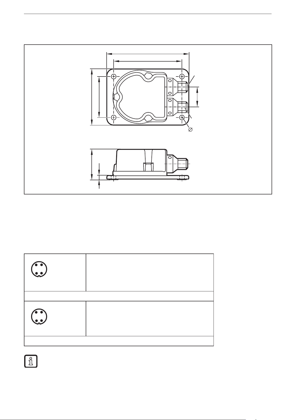
5 Scale drawing
62
45
90
75
M12x1
22
M12x1
5,3
33,2
4,5
6 Electrical connection
The inclination sensors are fitted with two round 4-pole M12 connectors (class A)
in accordance with IEC 60947-5-2. The M12 connectors are mechanically A-coded
in accordance with IEC 61076-2-101.
1: L+ 24 V DC (+Ub-D)
2: OUT2 switching output 2
M12 connector (left)
3: L- ground (GND)
4: OUT1 switching output 1 or IO-Link
1: L+ 24 V DC (+Ub-A)
2: A2 analogue output 2
3: L- ground (GND)
4: A1 analogue output 1
M12 connector (right)
The ground connections of the two round M12 connectors are directly
connected to each other internally; the supply voltage connections are
decoupled from each other.
6
Page 7

Inclination sensor JN
7 IO-Link interface
The inclination sensors have a standardised IO-Link interface V1.1 and an IO-Link
device description according to IEC 61131-9. All measured values and parameters
are accessible via "Indexed Service Data Unit" (ISDU).
The individual configuration can be saved in the internal permanent memory
(EEPROM).
In the context of this unit manual the operating principle of IO-Link is assumed to
be known. In this connection we refer to the latest documents "IO-Link System
Description", "IO-Link Interface and System Specification" and "IO Device
Description Specification" published by the IO-Link consortium
(http://www.io-link.com).
The following features characterise the IO-Link interface:
Communication
UK
● IO-Link revision V1.1
● Bit rate 38,400 bits/s (COM2)
● Minimum cycle time 5 ms
● Parameters are checked for valid values (range check)
Supported are
● SIO mode
● Block parameter setting
● Data storage
● Device Access Locks
● Device status and detailed device status
Manufacturer and device identification
Vendor ID 310 / 0x0136
Vendor Name ifm electronic gmbh
Vendor Text www.ifm.com
Device ID 416 / 0x0001A0
Product Name JN2200
Product ID JN2200
Product Text 2-axis inclination Sensor
7
Page 8

Inclination sensor JN
The mandatory parameters indicated in the index range 0...63 in the IO-Link
specification are summarised in the table below
Index Sub-
index
0 1...16 UINT8 Direct
1 1...16 UINT8 Direct
2 0 UINT8 System
Type Value Content Read /
Parameter
Page 1
Parameter
Page 2
command
Length
Write
See IO-Link specification R 1 each
See IO-Link specification R 1 each
0x82
0xB2
0xE0
0xE1
0xE2
0xE3
→
Factory setting
→
Start self-test
→
Set Teach XYZ
→
Reset Teach XYZ
→
Set Zero XYZ
→
Reset Zero XYZ
W 1
byte
0xC3
0xC5
0xC4
0xC6
0xCB
0xCC
0xCD
0xCE
3 0 UINT8 Data storage See IO-Link specification R/W Var
12 0 UINT16 Device Access
Locks
See IO-Link specification R/W 2
→
Teach SP1
→
Teach rP1
→
Teach SP2
→
Teach rP2
→
Teach ASP1
→
Teach AEP1
→
Teach ASP2
→
Teach AEP2
8
Page 9

Inclination sensor JN
Index Sub-
index
13 0 Profile
14 0 PD Input
Type Value Content Read /
Characteristic
Descriptor
0x0001 8000 8002 8003
0001 → Smart Sensor Profile
(DeviceProfileID)
8000 → Device Identification Objects
(FunctionClassID)
8002 → ProcessDataVariable
(Function-ClassID)
8003 → Diagnostics
(FunctionClassID)
0x010600 020808 031010 031020
010600→Type=SetOfBool, Len=6,
Off-set=0
020808→Type=UInteger, Len=8,
Off-set=8
031010→Type=Integer, Len=16,
Off-set=16
031020→Type=Integer, Len=16,
Off-set=32
Length
Write
R 8
R 12
byte
UK
16 0 ASCII Vendor Name ifm electronic gmbh R 19
17 0 ASCII Vendor Text www.ifm.com R 11
18 0 ASCII Product Name JN2200 R 6
19 0 ASCII Product ID JN2200 R 6
20 0 ASCII Product Text 2-axis inclination sensor R 25
21 0 ASCII Serial Number R 12
22 0 ASCII Hardware
revision
23 0 ASCII Firmware
Revision
24 0 ASCII Application
Specific Tag
36 0 UINT8 Device status
XX R 2
xx R 5
*** R/W max.
16
00
01
02
→
Device operating properly
→
Maintenance required
→
Out-of-Specification
R 1
37 0 UINT8 Detailed
Device Status
→
03
04
Array [13] of Events
(1-byte EventQualifier each
+ 2-byte EventCode)
Functional-Check
→
Failure
R 39
9
Page 10

Inclination sensor JN
Index Sub-
index
40 0 --- Process Data
Type Value Content Read /
Input
0x cccc bbbb aaaa
cccc
→
PDVal2 (INT16)
→
bbbb
aaaa
Bit 0
Bit 1
Bit 2
Bit 3
Bit 4
Bit 5
Bit 6
Bit 7
Bit 8
PDVal1 (INT16)
→
Bool/DevStatus (UINT16)
→
--SW 1
→
--SW 2
→
--
→
--
→
Measuring method
→
Self-test active
→
--
→
--
→
DeviceStatus LSB
Write
R 6
Length
byte
→
Bit 9
Bit 10
Bit 11
Bit 12
Bit 13
Bit 14
Bit 15
DeviceStatus
→
DeviceStatus MSB
→
--
→
--
→
--
→
--
→
--
8 Basic system settings and diagnostics
The JN2200 inclination sensor can be used for inclination or vibration
measurement. All parameter values that are of importance to the selected
measuring method are nevertheless always accessible and are saved in the
internal memory. They are part of the IO-Link data storage.
If the measuring method "vibration" is set, all parameters for setting the inclination
measurement and all angle-dependent parameters for the switching and analogue
outputs keep their values.
Characteristic values of the sensors such as measuring cell temperature and
current heating power as well as the results of the last self-test can be read via
own ISDU indices.
10
Page 11

Inclination sensor JN
Index Sub-
index
4102 0 UINT8 Heating
4106 0 UINT8 Measuring
4110 0 INT16 MEMS
4111 0 UINT16 Heating power [mW] R 2
4112 0 INT16 Operating
4113 0 UINT8 Self-test status
4114 0 UINT8 Self-test result
Type Value Content Read /
Write
R/W
R/W
R 1
R 1
method
temperature
temperature
0
→
Heating off
→
Heating on
1
0
→
Angle [0.01°]
→
veff [0.1 mm/s] / app [mg]
1
[1/10 °C] R 2
[1/10 °C] R 2
→
No self-test active
0
→
Self-test active
1
Bit2 = 1
Bit2 = 0
Bit1 = 1
→
x axis OK
→
x axis fault
→
y axis OK
Length
byte
UK
→
Bit1 = 0
Bit0 = 1
Bit0 = 0
y axis fault
→
z axis OK
→
z axis fault
8.1 Heating (ISDU index 4102)
To ensure good temperature stability over the whole temperature range, the
measuring cell is regulated to a constant temperature. The regulation of the
heating is activated by the factory and can be deactivated by writing the value 0 to
the parameter of the heating (ISDU index 4102).
This has the following effects
● Reduction of temperature stability
● Current consumption decreases when operating
● Accuracies deviate from the indications in the data sheet
8.2 Measuring method (ISDU index 4106)
The required measuring method is set to the inclination or vibration measurement
via the ISDU index 4106.
8.3 Measuring cell and ambient temperature, heating power (ISDU index
4110...4112)
Measuring cell and ambient temperature inside the housing are redetermined
every 200 ms. They can be read via ISDU access (in any device status). The
signed 16-bit values (two's complement) indicate the temperature in 1/10 °C.
11
Page 12

Inclination sensor JN
8.4 MEMS self-test (system command 0xB2 and ISDU index 4114)
To check the function of the measurement axes a self-test of the measuring cell
can be carried out.
► Activate the MEMS self-test per IO-Link system command 0xB2 (ISDU index 2
= 0xB2).
The self-test takes about 2 s. During the self-test both in the ISDU index 4113 and
in the process data (ISDU index 40) the status flag is set to "1".
After the end of the self-test these flags are again set to the value "0". During the
self-test no process data can be measured.
The test result of the individual axes is coded in a byte and can be read from the
self-test register (ISDU index 4114):
00000xxxb
The 3 least significant bits code the internal x, y, z measurement axes
Bit 0: axis faulty
Bit 1: axis functional
9 Parameter setting of the inclination sensor
If the measuring method is set to inclination measurement (ISDU index 4106 = 0),
it can be adapted via the following parameters:
Index Sub-
index
4100 0 UINT8 Angle calculation
4101 0 UINT8 FIR filter step angle
Type Value Content Read /
Write
0
→
Perpendicular
→
Euler
1
→
Gimbal 1X
2
→
Gimbal 1Y
3
→
FIR deactivated
0
R/W
R/W
Length
byte
4103 0 UINT8 Quadrant
correction
4104 0 UINT8 Teach x / y / z axis
status
12
→
FIR 10 Hz
1
→
FIR 5 Hz
2
→
FIR 1 Hz
3
→
FIR 0.5 Hz
4
0
→
off
→
on (± 180°)
1
1
→
Teach active
(relative measurement)
→
Teach inactive
2
(absolute measurement)
R/W 1
R 1
Page 13

Inclination sensor JN
Index Sub-
index
4105 0 UINT8 Zero x / y / z axis
Type Value Content Read /
Write
R 1
status
1
→
Zero active
(relative measurement)
→
Zero inactive
2
(absolute measurement)
Length
byte
10 Angle calculation (ISDU index 4100)
To be able to adapt the inclination sensor to the different applications as easily
as possible, the measured inclination information is converted into different angle
indications. The requested angle indication is set by selecting the respective
option.
With this angle definition a sensor coordinate system is used which is defined as
follows:
– The mounting plane corresponds to the xy plane.
– The z axis is perpendicular to the mounting plane (according to the right-
hand rule).
UK
– The x axis is represented by an edge of the mounting plate which shows in
direction of the printed x arrow.
– The y axis is then perpendicular to the plane spanned by the z and x axes.
10.1 Perpendicular angle (ISDU index 4100 = 0)
Using the indication of the two perpendicular angles the inclination of the sensor
coordinate system towards the direction of gravitation is described.
The first provided value corresponds to a rotation about the y axis of the sensor
and is called "longitudinal inclination value" (index 40, process data PDVal1).
The value corresponds to the angle [°] which the gravitation vector spans with the
yz plane.
The second provided value corresponds to a rotation about the x axis of the
sensor and is called "lateral inclination value" (index 40, process data PDVal2).
The value corresponds to the angle [°] between the gravitation vector and the xz
plane of the sensor.
In the case of an inclination in a plane (rotation of an axis with the second axis remaining
perpendicular) the perpendicular angle and gimbal angle are always identical.
13
Page 14

Inclination sensor JN
10.2 Euler angle (ISDU index 4100 = 1)
In this setting the two provided angle values are to be interpreted as Euler angle.
The current sensor orientation is determined by two successive rotations from
the horizontal position. The "inclination value longitudinal" indicates the angle
X [°] at which the z axis of the sensor is inclined. The "inclination value lateral"
corresponds to the angle Y [°] at which the sensor was then rotated about the
(inclined) z axis.
Interpretation
The first angle value X corresponds to the angle between the gravitation vector
and the sensor's z axis (slope inclination, gradient angle) whereas the second
angle value Y indicates the direction in which the slope inclination matches the
coordinate system.
Value range for this option
– Inclination value longitudinal (gradient angle): -90°…+90°
– Inclination value lateral (angle of direction): -180°…+180°
Critical point
With a gradient angle of 0° the sensor is in a horizontal position. In this position the
second angle (angle of direction) is useless. In practice, it is to be expected that
the value of the second angle will vary very strongly even if the sensor is virtually
motionless.
10.3 Gimbal angle X (ISDU index 4100 = 2)
As with the Euler angle the current orientation of the sensor is described by two
successive rotations from the horizontal position.
But the current orientation now arises from a rotation about the y axis with the
angle value X [°] indicated by the "inclination value longitudinal" as well as from
a rotation which then follows about the (now rotated) x axis with the angle Y [°]
"inclination value lateral".
Interpretation
If you imagine the sensor as a plane whose body shows in x direction and
whose wings in y direction, the "inclination value longitudinal" corresponds to the
longitudinal inclination of the plane (pitch angle) and the "inclination value lateral"
to the bank angle (roll angle) of the plane.
Value range
– Inclination value longitudinal: -90°…90°
– Inclination value lateral: -180°…180°
Critical point
With a longitudinal inclination of ± 90° ("plane" flies vertically downwards or
upwards) the roll angle makes a rotation about the gravitational axis which cannot
14
Page 15

Inclination sensor JN
1
2
3
4
5
6
be detected by the inclination sensor. In this condition the "inclination value lateral"
is insignificant. In practice, the "inclination value lateral" will vary very strongly
when it is close to this condition even if there is only little movement.
10.4 Gimbal angle Y (ISDU index 4100 = 3)
This setting corresponds to the setting described in 10.3 with the difference that
the order of the two rotations is now inverted. In this option the measured object
is first rotated about its x axis with the angle Y [°] "inclination value lateral". The
UK
measured object is then rotated about the y axis (which is now inclined) with the
angle value X [°] indicated by the "inclination value longitudinal" of the sensor.
As a result of this the measured values of the gimbal angle X and the gimbal angle
Y are identical as long as the measured object is only rotated about one of the
sensor's axes. The measured values of the two options do not differ until a general
rotation is made about the two sensitivity axes.
10.5 Explanatory example
The different angle definitions will be illustrated using a simple example. An
excavator moves up and down an embankment (illustration). The embankment is
angled at 30°. The inclination sensor is installed so that the positive y axis of the
sensor shows in driving direction of the excavator.
Excavator
position
1 0° 0° 0°
2 0° -30° 30° 0° 0° -30° 0° -30°
3 20° -20° 30° 45° 20° -22° 22° -20°
4 30° 0° 30° 90° 30° 0° 30° 0°
5 30° 0° 30° 90° 30° 0° 30° 0°
6 0° 30° 30° 180° 0° 30° 0° 30°
Perpendicular angle Euler Gimbal X Gimbal Y
Longitudinal Lateral Longitudinal Lateral Longitudinal Lateral Longitudinal Lateral
Undefined
0° 0° 0° 0°
15
Page 16

Inclination sensor JN
10.6 Limit frequency digital filter (ISDU index 4101)
With the sensor it is possible to make continuously arising angle values insensitive
to external interfering vibrations.
Using a configurable filter (digital FIR filter) interfering vibrations can be
suppressed. The limit frequency of the filter is set via the FIR filter step (ISDU
index 4101).
10.7 Quadrant correction (ISDU index 4103)
Quadrant correction means an extension of the angle indication to the measuring
range ± 180° (corresponds to ISDU index 4103 = 1).
The following conditions apply to the different angle calculations:
Perpendicular angle: longitudinal (X) and lateral (Y) are corrected.
Euler: only lateral (Y) is corrected.
For the gimbal angles the roll angle is corrected.
Gimbal X: longitudinal X (pitch angle), lateral Y (roll angle)
Gimbal Y: longitudinal X (roll angle), lateral Y (pitch angle)
10.8 Set zero point (system commands 0xE2 and 0xE3 and ISDU index
4105)
To set the zero point the sensor is rotated to the requested position and the current
position is set as "0". In this respect the system command 0xE2 has to be sent via
the IO-Link interface (ISDU index 2 = 0xE2).
The sensor then calculates the offset to the zero point shift and saves it in the
permanent memory. From then on the offset is subtracted from the angle.
To delete the zero point, the system command 0xE3 has to be sent via the IO-Link
interface (ISDU index 2 = 0xE3). The status of the zero point (set or deleted) can
be read at any time via the ISDU index 4105.
10.9 Set teach (system commands 0xE0 and 0xE1 and ISDU index 4104)
Should it not be possible to integrate the inclination sensor into the measured
object so that the coordinate system of the sensor and object coordinate system
match, the teach function enables the creation of a new reference system.
The new reference system xb,yb,zb is defined so that its zb direction corresponds to
the direction of gravitation at the teach moment. The xb direction of the reference
system results from the projection of the xs axis of the sensor to the xbyb plane
of the reference system. The yb axis then corresponds to the direction which is
perpendicular to both the zb and the xb axis.
To set the teach point, the system command 0xE0 has to be sent via the IO-Link
interface (ISDU index 2 = 0xE0). To delete the teach point, the system command
0xE1 has to be sent via the IO-Link interface (ISDU index 2 = 0xE1).
16
Page 17

Inclination sensor JN
The status of the teach point (set or deleted) can be read at any time via the ISDU
index 4104.
The result of this is that at the teach moment the xs axis must not be parallel to the direction of
gravitation. As long as the value for the ISDU index 4104 is 1, all angle indications are converted into
the new reference system.
The teach operation can, for example, be as follows:
The measured object with the non-aligned inclination sensor is brought into a
known horizontal position. In this position the teach function is carried out, thus
defining the new reference system. All provided angle values then refer to this new
reference system.
UK
Even with an inclination sensor which is installed at an angle note that the x axis (x
sensor is parallel to the xbzb plane of the requested reference system.
Explanatory example
Inclination sensor installed at an angle in the
coordinate system of the workpiece. The coordinate
system of the sensor is transferred to the coordinate
system of the workpiece by teaching the inclination
The raw data of the sensor is indicated in the
coordinate system of the sensor.
In teach mode the data is converted into the
coordinate system of the workpiece.
sensor when the workpiece is horizontally aligned.
axis) of the
s
The example shows a rotation of 30° about the y axis of the coordinate system of
the workpiece.
Perpendicular angle
without teach
Longitudinal
angle value
Lateral
angle value
-13.2° -29.3° 0° 0° -45.5° -29.5° -30° 0°
Teach mode Perpendicular angle
without teach
Longitudinal
angle value
Lateral angle
value
Longitudinal
angle value
Lateral angle
value
Teach mode
Longitudinal
angle value
Lateral angle
value
17
Page 18

Inclination sensor JN
11 Parameter setting of the vibration measurement
If the measuring method is set to vibration measurement (ISDU index 4106 = 1),
the sensor can be adapted to the respective application via the following IO-Link
parameters.
Index Sub-
index
4107 0 UINT8 Axis selection for vibration
4108 0 UINT8 FIR filter step
Type Value Content Read /
measurement
for vibration measurement
1 (001b )
2 (010b)
4 (100b)
3 (011b)
5 (101b)
6 (110b)
7 (111b)
(x/y/z)
0 → FIR deactivated
→
1
→
2
→
3
→
4
→
z axis
→
y axis
→
x axis
→
y/z axis
→
x/z axis
→
x/y axis
→
all 3 axes
FIR 0.1...1 Hz
FIR 0.1...10 Hz
FIR 1...10 Hz
FIR 2...400 Hz
Write
R/W 1
R/W 1
Length
byte
→
FIR 10...400 Hz
5
4109 0 UINT8 Measuring range for
vibration measurement
0
1
2
→
→
→
± 2 g
± 4 g
± 8 g
R/W 1
If the vibration measurement is active, the sensor provides two different
characteristic values instead of the angle values.
The X angle value now corresponds to the effective value of the vibration velocity
(v
[1/10 mm/s]), the Y angle value to the maximum vibration acceleration (a
eff
peak
[mg]).
11.1 Configure measuring plane (ISDU index 4107)
The measurement categories are calculated by default from the measurement
axes of the internal acceleration measuring cell as follows:
v effective=√(v²x+ v²y+ v²z)
a peak=√(a²x+ a²y+ a²z)
The definition of the coordinate system of the acceleration measuring cell
corresponds to the coordinate system of the sensor. The mounting plane
corresponds to the xy plane and the z axis is perpendicular to the mounting plane.
18
Page 19

Inclination sensor JN
The last three LSBs of the parameter for the configuration of the measuring plane
(ISDU index 4107) set which measuring axes are included in the calculation of the
final result. By default the characteristic values of the vibration measurement for all
3 axes are measured.
x axis active: bit 2 = 1
x axis not active: bit 2 = 0
y axis active: bit 1 = 1
y axis not active: bit 1 = 0
z axis active: bit 0 = 1
z axis not active: bit 0 = 0
11.2 FIR filter with vibration measurement (ISDU index 4108)
The sensor provides the possibility to filter the vibration signal. Depending on
the application the frequency range to be measured can be adapted. The limit
frequency of the filter is set via the FIR filter step (ISDU index 4108).
When the FIR filter has been changed for V
or a
eff
, the measured values are
peak
only transferred when the filters are in the steady state. This settling time depends
on the set values and can be taken from the table below:
0.1...1 Hz: approx. 70 s
0.1...10 Hz: approx. 70 s
1...10 Hz: approx. 12 s
UK
2...400 Hz: approx. 9 s
10...400 Hz: approx. 5 s
11.3 Measuring range of the vibration measurement (ISDU index 4109)
The measuring range of the vibration measurement can be set up to a maximum
value. The measuring range of the internal acceleration measuring cell can
be limited for different applications to 2 g, 4 g or 8 g (maximum value) (g =
gravitational acceleration).
12 Process data transfer via IO-Link
The sensors transfer the cyclic process data (process exchange data) without
mutual interference by simultaneous transfer of parameters, commands or events
(on-request data).
The process data consist of 6 object data. The meaning of process value 1
and process value 2 depends on the measuring method set via the ISDU index
4106 (inclination or vibration measurement). The selected measuring method is
displayed at any time via a status bit.
19
Page 20

Inclination sensor JN
Another status bit indicates if the process values are not informative due to a
running self-test (in addition to ISDU index 4113).
The device status is indicated at any time via a bit field (in addition to ISDU index
36).
Name Data type Bit
offset
Switching
output 1
Switching
output 2
Measuring
method
Self-test active Boolean 5 1 0 = self-test inactive
Device status UINT 8 3 000 = device functions reliably
Boolean 0 1 0 = inactive
Boolean 1 1 0 = inactive
Boolean 4 1 0 = inclination
Bit
length
Value range Unit
1 = active
1 = active
1 = vibration
1 = self-test running
001 = maintenance successful
010 = device outside the
specification
011 = check function
100 = fault
Process value 1Int 16 16 Angle X for inclination measurement
V
for vibration measurement
eff
Process value 2Int 32 16 Angle Y for inclination measurement
A
for vibration measurement
pp
1/100 °
1/10 mm/s
1/100 °
1 mg (*)
(*) 1 mg = 1/1000 g, 1 g = 9.80665 m/s² standard acceleration
13 Parameter setting of the analogue outputs
There are two analogue outputs (right M12 connector) on the sensor to pass
on the measured process values (inclination angle or vibration) to a machine
controller (PLC).
M12 connector (right)
1: L+ 24 V DC (+Ub-A)
2: A2 analogue output 2
3: L- ground (GND)
4: A1 analogue output 1
The characteristics of the analogue output can be adapted to the respective
application via the following parameters.
20
Page 21

Inclination sensor JN
Index Sub-
index
620 INT16 ASP1 inclination measurement
621 INT16 AEP1 inclination measurement
630 INT16 ASP2 inclination measurement
631 INT16 AEP2 inclination measurement
622 INT16 ASP1 vibration measurement v
623 INT16 AEP1 vibration measurement v
632 INT16 ASP2 vibration measurement a
633 INT16 AEP2 vibration measurement a
Type Value Content Read /
(x axis)
(x axis)
(y axis)
(y axis)
eff
eff
peak
peak
Length
Write
[1/100 °] R/W
[1/100 °] R/W
UK
[1/100 °] R/W
[1/100 °] R/W
[1/10 mm/s] R/W
[1/10 mm/s] R/W
[mg] R/W
[mg] R/W
660 UINT8 Analogue output mode
→
Voltage Output
0
→
Current Output
1
R/W 1
The two analogue outputs can be set by the user via the ISDU index 660 as
current source with 4...20 mA loop current (ISDU index 660 = 1) or as voltage
source with 2...10 V output voltage (ISDU index 660 = 0).
The assignment of the units of measurement to output 1 or output 2 is made
according to the table below in dependence on the selected measuring method
(ISDU index 4106) and angle calculation method (ISDU index 4100):
Measuring method Output 1 Output 2
Inclination measurement
perpendicular
Index 4106: 0 Index 4100: 0
Inclination measurement Euler
Index 4106: 0 Index 4100: 1
Inclination measurement gimbal
1X
Index 4106: 0 Index 4100: 2
Perpendicular angle longitudinal Perpendicular angle lateral
Euler angle longitudinal Euler angle lateral
Gimbal angle X longitudinal Gimbal angle X lateral
Inclination measurement gimbal
1X
Index 4106: 0 Index 4100: 3
Gimbal angle Y longitudinal Gimbal angle Y lateral
21
Page 22

Inclination sensor JN
Measuring method Output 1 Output 2
Vibration measurement
Index 4106: 1
Vibration velocity v
eff
Vibration acceleration a
peak
The measured values can be mapped to the output signal range of 4...20 mA or
2...10 V, depending on the selected measuring method (inclination or vibration).
The parameters ASP (analogue start point) and AEP (analogue end point) as from
ISDU index 620 serve this purpose.
The start and end points are indicated as a signed 16-bit integer value according
to the measuring method, e.g. -4500 for -45.00 ° or 1200 for 1.200 g.
The analogue start point ASP always has to be smaller than the analogue end point AEP; otherwise
setting of the parameters is refused by the sensor.
The minimum distance between ASP and AEP of 1 ° for inclination measurement or 1 mm/s and 1 mg
for vibration measurement always has to be observed; otherwise setting of the parameters is refused
by the sensor.
If an ASP is to be set to a new value which is above the respective AEP, the AEP has to be set to a
considerably higher value beforehand. Otherwise the sensor refuses setting of the parameter.
In analogy, AEP has to be adapted to ASP before changing.
The values configured for the analogue start and end points remain unchanged even if other
parameters (such as quadrant correction ISDU index 4103 and angle calculation method ISDU index
4100 in the event of inclination measurement) are changed.
The user has to ensure that the values for the start and end points are in a suitable range before
parameters are changed on the sensor to be able to use the entire output value range for current
(4...20 mA) or voltage (2...10 V).
Example (original setting)
Angle calculation perpendicular (ISDU index 4100: 0)
Quadrant correction off (ISDU index 4103: 0)
Analogue output mode current (ISDU index 660: 1)
Analogue start point 2 - 90.00 ° (ISDU index 630: -9000)
Analogue end point 2 + 90.00 ° (ISDU index 631: 9000)
The angle values measured for the second axis vary in the range -90° to +90
° on the basis of the selected angle calculation and the switched-off quadrant
correction. That results in a linear value range of 4...20 mA (shown in green) for
the second current output.
New setting
Angle calculation Euler (ISDU index 4100: 1)
The angle values measured for the second axis now vary in the range -0° to
+180°on the basis of the changed angle calculation.
Since the analogue start and end points for this axis remain to be set to -90 ° or
+90 °, only the angle range between 0 ° and +90 ° can be mapped to the current
22
Page 23

Inclination sensor JN
-
4 mA
8 mA 12 mA
16 mA
20 mA
output in the value range between 12 mA and 20 mA (shown in red).Since angle
values between -90 ° and 0 ° are "never" reached, the current output remains on
the lower end (0 °) at 12 mA and not 4 mA.
Current
90 °
- 45 °
0 °
+ 45 °
+90 °
+ 135 ° + 180 °
+225 ° +270 ° +315 ° +360 °
Angle
13.1 Analogue output as current source 4...20 mA
If both analogue outputs were set as current source, the measured angles
(according to the selected measuring method as perpendicular, Euler or gimbal
angle) are provided as loop in the value range 4...20 mA according to the industrial
standard.
JN2200 inclination sensor PLC machine controller
+ 24 V
OUT2 4...20 mA
OUT1
I1
R
L
R
L
≥ 500 Ω
mA
4...20 mA
UK
I2
R
L
mA
The measured values are implemented to the current intensity in the current
loop as shown below. Angle values smaller than the set start point are constantly
mapped to the lowest value of 4 mA. Angle values greater than the set end point
are constantly mapped to the highest value of 20 mA.
23
Page 24

Inclination sensor JN
I
[mA]
20
4
Angle [°]
ASP
e.g. - 45 ° → ASP = -4500
AEP
e.g. + 45 ° → AEP = +4500
13.2 Analogue output as voltage source 2...10 V
Alternatively, the two analogue outputs can be set as voltage source. Then the
measured angles (according to the selected measuring method as perpendicular,
Euler or gimbal angle) are provided as output voltage in the value range 2...10
V.Due to the internal circuit details the output cannot be controlled down to 0 V.
Therefore the output voltage difference is limited to 2...10 V as opposed to the
common standard of 0...10 V.
JN2200 inclination sensor PLC machine controller
+24 V
2...10 V OUT1
U
1
R
L
V
24
2...10 V OUT2
U
RL≥10 kΩ
R
2
L
V
Page 25

Inclination sensor JN
10
U [V]
The measured values are implemented to the voltage intensity on the outputs
as shown in the diagram below. Angle values smaller than the set start point are
constantly mapped to the lowest value of 2 V. Angle values greater than the set
end point are constantly mapped to the highest value of 10 V.
UK
2
Angle [°]
ASP
e.g. - 60 ° → ASP = -6000
AEP
e.g. + 120 ° → AEP = +12000
13.3 Teach ASP and AEP via system commands
The analogue start points ASP1 and ASP2 as well as the analogue end points
AEP1 and AEP2 can be taught according to the selected measuring method
(inclination or vibration measurement) via IO-Link system commands (ISDU index
2).
When the respective system command is sent, the start and end points are
adopted according to the current process value.
System command
(ISDU index 2)
Action
0xCB Teach ASP1
0xCC Teach AEP1
0xCD Teach ASP2
0xCE Teach AEP2
When an analogue start or end point has been taught by sending a system command, the new
values for the start or end points should be checked by reading the respective ISDU index.
Only then can it be seen, if teaching was successful or was refused by the sensor due to non-
observance of the rules "ASP < AEP" and "AEP - ASP ≥ minimum distance".
25
Page 26

Inclination sensor JN
13.4 Fault message on analogue outputs
In the event of a sensor fault (MEMS cell defective) a constant voltage of 1.0 V or
a constant current of 2 mA is provided according to the set output function (ISDU
index 660).
These values can be distinguished from the state "wire break" (0 V or 0 mA) by the
common inputs of a plant controller (PLC) and they are also considerably outside
the common value range of 2...10 V or 4...20 mA.
14 Parameter setting of the digital switching outputs
The sensor has two digital switching outputs (left M12 connector) which can
provide switching thresholds set by the user for the measured process values
(inclination or vibration measurement) to a machine controller (PLC), for example.
M12 connector (left)
1: L+ 24 V DC (+Ub-D)
2: OUT2 switching output 2
3: L- ground (GND)
4: OUT1 switching output 1 or IO-Link
Switching output 1 is also the communication cable for IO-Link and is referred to
as "C/Q" (Port Class A) in the IO-Link specification. Switching output 2 uses the
pin called "DI/DQ" in the IO-Link specification.
The use as switching output is only possible, if no IO-Link master tries to
communicate with the sensor and the sensor is in the SIO mode.
The assignment of the switching outputs in dependence on the selected
measuring method (ISDU index 4106) and angle calculation method (ISU index
4100) can be seen in the table below.
Measuring method Output 1 Output 2
Inclination measurement
perpendicular
Index 4106: 0 Index 4100: 0
Inclination measurement Euler
Index 4106: 0 Index 4100: 1
Inclination measurement gimbal
1X
Index 4106: 0 Index 4100: 2
26
Perpendicular angle longitudinal Perpendicular angle lateral
Euler angle longitudinal Euler angle lateral
Gimbal angle X longitudinal Gimbal angle X lateral
Page 27

Measuring method Output 1 Output 2
Inclination sensor JN
Inclination measurement gimbal
1Y
Index 4106: 0 Index 4100: 3
Vibration measurement
Index 4106: 1
Gimbal angle Y longitudinal Gimbal angle Y lateral
Vibration velocity v
eff
Vibration acceleration a
The following parameters can be set for switching output 1 via IO-Link
Index Sub-
index
531 0 UINT8 FOU1 output 1
580 0 UINT8 ou1 output 1
Type Value Content Read /
Write
in case of a fault
function
1 → OU (no fault
indication)
→
ON (closed)
2
→
OFF (open)
4
→
TOGGLE (2 Hz)
8
3 → Hysteresis normally
open [Hno]
R/W 1
R/W 1
peak
UK
Length
581 0 UINT16 dS1
582 0 UINT16 dr1
583 0 INT16 SP1
584 0 INT16 rP1
4115 0 UINT8 LOGIC_OUT1
switching delay
switch-off delay
for inclination
measurement
for inclination
measurement
logical connective for
switching output 1
→
Hysteresis normally
4
closed [Hnc]
→
Window normally
5
open [Fno]
→
Window normally
6
closed [Fnc]
[ms], Step/Round 10
0 ≤ DFO ≤ 10000 8 ms
[ms], Step/Round 10
0 ≤ DFO ≤ 10000 8 ms
Angle [1/100 °] R/W 2
Angle [1/100 °] R/W 2
0
→
No connective
→
Log. OR with output 2
1
→
Log. AND
2
with output 2
R/W 2
R/W 2
R/W 1
585 0 INT16 SP1
for vibration
measurement
v
[1/10 mm/s] R/W 2
eff
27
Page 28

Inclination sensor JN
Index Sub-
index
586 0 INT16 rP1
Type Value Content Read /
Write
for vibration
measurement
v
[1/10 mm/s] R/W 2
eff
The following parameters can be set for switching output 2 via IO-Link
Index Sub-
index
532 0 UINT8 FOU2 output 2
590 0 UINT8 ou2 output 2
Type Value Content Read /
Write
in case of a fault
function
1 → OU (no fault
indication)
→
ON (closed)
2
→
OFF (open)
4
→
TOGGLE (2 Hz)
8
3
→
Hysteresis normally
open [Hno]
R/W 1
R/W 1
Length
Length
591 0 UINT16 dS2
592 0 UINT16 dr2
593 0 INT16 SP1
594 0 INT16 rP1
4116 0 UINT8 LOGIC_OUT2
switching delay
switch-off delay
for inclination
measurement
for inclination
measurement
logical connective for
switching output 2
→
Hysteresis normally
4
closed [Hnc]
→
Window normally
5
open [Fno]
→
Window normally
6
closed [Fnc]
[ms], Step/Round 10
0 ≤ DFO ≤ 10000 8 ms
[ms], Step/Round 10
0 ≤ DFO ≤ 10000 8 ms
Angle [1/100 °] R/W 2
Angle [1/100 °] R/W 2
0
→
No connective
→
Log. OR with output 1
1
→
Log. AND
2
with output 1
R/W 2
R/W 2
R/W 1
595 0 INT16 SP2
for vibration
measurement
596 0 INT16 rP2
for vibration
measurement
28
a
[mg] R/W 2
peak
a
[mg] R/W 2
peak
Page 29

Inclination sensor JN
Moreover the following parameters can be set (via IO-Link) for both switching
outputs:
Index Sub-
index
500 0 UINT8 P-n
530 0 UINT16 dFo
Type Value Content Read /
switching mode
delay in case of a fault
0
→
PnP
(output to +Ub)
→
nPn
1
(output to GND)
[ms], Step/Round 10
0 ≤ DFO ≤ 10000 8 ms
Length
Write
R/W 1
UK
R/W 2
29
Page 30

Inclination sensor JN
On
Of
14.1 Output function ou1 and ou2
The output function OU can be set for both switching outputs to one of the
following values via the ISDU indices 580 and 590:
● 3 = hysteresis (normally OFF; normally open) [Hno]
● 4 = hysteresis (normally ON; normally closed) [Hnc]
● 5 = window (normally OFF; normally open) [Fno]
● 6 = window (normally ON; normally closed) [Fnc)
14.2 Output function "hysteresis (normally OFF; normally open)" [Hno]
The set point SP as from which the respective switching output is switched (red
path) can be defined for the measured process values.
Below this threshold the output remains switched off. As soon as the switching
threshold SP has been reached once, the measured process values must
decrease below the set reset point rP so that the switching output is switched off
again (green path).The hysteresis thus reached can be used to avoid constant
switching on and off in the event of minor process value fluctuations.
The respective parameter SP (set point) and rP (reset point) are used for setting.
Switching output
f
Angle [°]
Hysteresis
rP
e.g. 45 ° → rP = 4500
SP
e.g.: 60 ° → SP = 6000
14.3 Output function "hysteresis (normally ON; normally closed)" [Hnc]
As compared to the previous output function, the output function "hysteresis
(normally ON)" uses inverted logic so that the output is first of all switched on for
small process values.
If the set set point SP is exceeded, the respective output is switched off (red path).
30
Page 31

Inclination sensor JN
On
Of
As soon as the switching threshold SP has been reached once, the measured
process values must decrease below the set reset point rP so that the switching
output is switched on again (green path).
Switching output
f
UK
Hysteresis
rP
e.g. 45 ° → rP = 4500
SP
e.g.: 60 ° → SP = 6000
Angle [°]
31
Page 32

Inclination sensor JN
On
Of
14.4 Switching output "window (normally OFF; normally open)" [Fno]
As long as the measured process values are within a set value range, the
switching outputs can be activated with the output function "window (normally
OFF)".
As soon as the lower threshold rP is exceeded, the respective output switches to
the logic state "ON". If the measured values increase far above the threshold SP,
the output is switched off again (red path). The green path applies for decreasing
values respectively.
The switching behaviour thus achieved corresponds to an assessment "value is
within a valid window".
Switching output
f
Window
rP
e.g. 45 ° → rP = 4500
Angle [°]
SP
e.g.: 60 ° → SP = 6000
32
Page 33

Inclination sensor JN
On
Of
14.5 Switching output "window (normally ON; normally closed)" [Fnc]
As compared to the previous output function the output function "window (normally ON)"
only uses inverted logic. Otherwise the behaviour is analogous.
Switching output
UK
f
Angle [°]
Window
rP
e.g. 45 ° → rP = 4500
SP
e.g.: 60 ° → SP = 6000
14.6 Set points SP and reset points rP
The set points SP and reset points rP controlling the output function "ou" can be
freely set within the permissible value ranges.
Set point Measuring method Minimum Maximum Unit
SP1 Inclination
measurement
rP1 Inclination
measurement
-17900 18000 1/100 °
-18000 17900 1/100 °
SP2 Inclination
measurement
rP2 Inclination
measurement
SP1 Vibration measurement 10 32000 1/10 mm/s
rP1 Vibration measurement 0 31990 1/10 mm/s
SP2 Vibration measurement 1 16000 1 mg
-17900 18000 1/100 °
-18000 17900 1/100 °
33
Page 34

Inclination sensor JN
Set point Measuring method Minimum Maximum Unit
rP2 Vibration measurement 0 15999 1 mg
The set point SP always has to be smaller than the respective reset point rP. Otherwise the sensor
refuses setting of the parameter.
The minimum distance between SP and rP of 1° for inclination measurement or 1 mm/s and 1 mg
for vibration measurement always has to be observed. Otherwise the sensor refuses setting of the
parameter.
If an rP is to be set to a new value which is above the respective SP, SP has to be set to a
considerably higher new value beforehand. Otherwise the sensor refuses setting of the parameter.
Analogously rP has to be adapted before SP is adjusted.
14.6.1 Setting via ISDU indices
The set points SP1 and SP2 as well as the reset points rP1 and rP2 can be set via
ISDU indices depending on the selected measuring method (inclination or vibration
measurement).
Index Sub-
index
583 0 INT16 SP1 for inclination measurement Angle X
584 0 INT16 rP1 for inclination measurement Angle X
585 0 INT16 SP1 for vibration measurement veff
586 0 INT16 rP for vibration measurement veff
593 0 INT16 SP2 for inclination measurement Angle Y
594 0 INT16 rP2 for inclination measurement Angle Y
595 0 INT16 SP2 for vibration measurement aPeak [mg] R/W 2
596 0 INT16 rP2 for vibration measurement aPeak [mg] R/W 2
Type Value Content Read /
Write
R/W 2
[1/100 °]
R/W 2
[1/100 °]
[1/10 mm/s]
[1/10 mm/s]
[1/100 °]
[1/100 °]
R/W 2
R/W 2
R/W 2
R/W 2
Length
14.7 Teach SP and rP via system commands
The set points SP1 and SP2 as well as the reset points rP1 and rP2 can be set via
IO-Link system commands (ISDU index 2) depending on the selected measuring
method (inclination or vibration measurement).
When the respective system commands are sent, the set and reset points are
adopted according to the current process value.
34
Page 35

Inclination sensor JN
System command
(ISDU index 2)
0xC3 Teach SP1
0xC5 Teach rP1
0xC4 Teach SP2
0xC6 Teach rP2
Action
UK
14.8 Switching delay dS1 / dS2 and switch-off delay dr1 / dr2
Via the ISDU index 581 and 582 or 591 and 592 one switching and switch-off
delay each can be set for both digital switching outputs after evaluation of the
output function "ou".
If no delay is indicated (0 ms), the digital outputs are set and reset according to the
switching function ou1 or ou2, directly in dependence on the associated process
values.
Set delay up to max. 10,000 ms.
The switching output is physically activated when the associated process value
switches the output according to the switching function ou1 or ou2 after the set
time.
Accordingly, a process value has to switch off the output according to the set
switching function ou1 or ou2 after the switch-off delay before the output is
physically switched off.
The actually effective delays are internally rounded to 10 ms.
35
Page 36

Inclination sensor JN
Switching and switch-off delay function
Process value
SP
rP
Hysteresis
t
t
dS dr
Switching
output
dS
t
14.9 Logical operation of the switching outputs
The two switching outputs can be logically linked with each other via the ISDU
indices 580 and 590 (after the evaluation of the process values) by means of the
output function "ou" and subsequent switching and switch-off delays.
The result of this logic connective is finally provided physically (if there is no
sensor fault (see following chapter)) as high-side or low-side switch (depending on
the setting of the ISDU index 500).
The following options for logical connectives can be selected:
● 0 = no logical connective
The switching output is only switched depending on the associated process
value (after level evaluation by the selected output function and after time
evaluation via the switching and switch-off delay dS and dr).The switching
output is only switched in dependence on process value 1 (angle X or veff;
switching output 2 only in dependence on process value 2 (angle Y or a
peak
).
● 1 = logical OR operator
The result of the level assessment via the selected output function and the time
evaluation via the switching and switch-off delays of a process value is logically
OR connected with the respective other assessed process value.
● 2 = logical AND operator
The result of the level assessment via the selected output function and the time
evaluation via the switching and switch-off delays of a process value is logically
AND connected with the respective other assessed process value.
36
Page 37

Inclination sensor JN
● 3 = constantly OFF (open)
The switching output is constantly switched off (irrespective of the process
value).
● 4 = constantly ON (open)
The switching output is constantly switched on (irrespective of the process
value).
14.10 Function of the switching outputs in case of a fault FOU1 or FOU2
The performance of the switching outputs in case of a fault or a problem taking
into consideration the set delay (see following chapter) can be determined via the
ISDU index 531 or 532.
● 1 = output function (no fault indication)
In this basic setting the switching outputs only react to the measured process
values. An existing sensor fault or failure (MEMS cell defective) has no
influence on the states of the switching outputs.
● 2 = output ON (closed)
If there is a sensor fault, the switching output is constantly switched on for the
duration of the failure. When the fault has been eliminated, the output resumes
its state according to the switching function and threshold in dependence on
the measured process values.
UK
● 4 = output OFF (open)
If there is a sensor fault, the switching output is constantly switched off for the
duration of the failure. When the fault has been eliminated, the output resumes
its state according to the switching function and threshold in dependence on
the measured process values.
● 8 = output TOGGLE (2 Hz)
If there is a sensor fault, the switching output is alternately switched on and
off for the duration of the fault in a 2 Hz interval. When the fault has been
eliminated, the output resumes its state according to the switching function and
threshold in dependence on the process values.
14.11 Delay of the switching outputs in case of a fault (dFo)
A delay in case of a fault can be set for both switching outputs together via the
ISDU index 530.
No delay (0 ms)
The faults are signalled according to the set fault function FOU1 or FOU2 (if ON,
OFF or TOGGLE has been selected for them) immediately on occurrence of a
sensor fault (MEMS cell defective). This signal ends at once the sensor fault has
been remedied.
Delay time up to max. 10,000 ms.
37
Page 38

Inclination sensor JN
PnP
nPn
The faults are signalled according to the set fault function FOU1 or FOU2 (if ON
OFF or TOGGLE has been selected) not before a sensor fault (MEMS cell) is
continuously present after the set time.
Accordingly, a sensor fault has to be eliminated continuously after the set time
before fault signalling is removed and the switching outputs return to the states
according to the process values.
The actually effective delay is internally rounded to 10 ms.
14.12 Output driver PnP or nPn
The physical switching characteristics for both digital outputs can be defined via
the ISDI index 500:
● 0 = high side switching (PnP): on activation the output is switched to +U
b
● 1 = low side switching (nPn): on activation the output is switched to ground
Switching output Switching output
OUT1/IO
OUT2
-Link
+24V
OUT1/IO-Link
OUT2
+24V
38
Page 39

Inclination sensor JN
14.13 Restore the factory setting (system command 0x82)
To reset the user-specific parameters of the inclination sensor to the factory setting
the IO-Link system command 0x82 "Factory Reset" (ISDU index 2 = 0x82) has to
be sent to the sensor.
With the system command "Factory Reset" all parameters are reset to the factory setting. This
process cannot be reversed.
UK
15 Status LED
The LEDs integrated in the two connectors indicate the respective state of the
device.
LED colour Flashing frequency Description
Green (left connector) Permanently on The device is in the "Run "state
Fashing IO-Link communication
Yellow (right connector) Permanently on Switching status OUT1 / OUT2
16 Maintenance, repair and disposal
The device is maintenance-free.
►Dispose of the device in accordance with the national environmental regulations.
17 Approvals/standards
The CE declaration of conformity and approvals can be found at:
www.ifm.com → Data sheet search → JN2200
39
Page 40

Inclination sensor JN
18 Factory setting
Index Sub-
index
500 0 UINT8 Switching performance of the
580 0 UINT8 ou1 output configuration
583 0 INT16 SP1 angle X
584 0 INT16 rP1 angle X
585 0 INT16 SP1 vibration measurement V
586 0 INT16 rP1 vibration measurement V
590 0 UINT8 ou2 output configuration
593 0 INT16 SP2 angle Y
594 0 INT16 rP2 angle Y
595 0 INT16 SP2 vibration measurement
Type Value Content Read /
digital outputs
eff
eff
aPeak
0
→
PnP
(high side switching; +Ub)
6
→
FNC
+ 9000
- 9000
6400 → 640 mm/s
(20% VMR)
6080 → 608 mm/s
(19% VMR)
6
+ 9000
‒ 9000
6400
(40% VMR)
→
→
→
- 90°
FNC
→
→
→
6400 mg
+ 90°
+90°
-90°
Write
R / W
R/W
R/W
R/W
R/W
R/W
R/W
R/W
R/W
R/W
596 0 INT16 rP2 vibration measurement
aPeak
620 0 INT16 ASP1 angle X
621 0 INT16 AEP1 angle X
622 0 INT16 ASP1 vibration measurement
Veff
623 0 INT16 AEP1 vibration measurement
Veff
630 0 INT16 ASP2 angle Y
631 0 INT16 AEP2 angle Y
632 0 INT16 ASP2 vibration measurement
aPeak
633 0 INT16 AEP2 vibration measurement
aPeak
660 0 UINT8 Type of the analogue output
4100 0 UINT8 Angle calculation
6240
→
6240 mg
(39% VMR)
-18000
+18000
0
32000
-18000
+18000
0
16000
1
4...20 mA
0
→
- 180°
→
→
0 mm/s
→
3200 mm/s
→
- 180°
→
→
0 mg
→
16000 mg
→
current output
→
perpendicular
+ 180°
+ 180°
R/W
R/W
R/W
R/W
R/W
R/W
R/W
R/W
R/W
R/W
R/W
4101 0 UINT8 FIR filter step angle
4102 0 UINT8 Heating
4103 0 UINT8 Quadrant correction
4104 0 UINT8 Teach x/y/z axis
40
2
→
low pass 5 Hz
1
→
heating on
1
→
± 180°
2
→
absolute
measurement
R/W
R/W
R/W
R
Page 41

Inclination sensor JN
Index Sub-
index
4105 0 UINT8 Zero x/y/z axis
4106 0 UINT8 Measuring method
4107 0 UINT8 Axis selection for
4108 0 UINT8 FIR filter step vibration
4109 0 UINT8 Measuring range vibration
Type Value Content Read /
2
→
absolute
measurement
0
→
angle indication
vibration measurement
7 → all 3 axes (x/y/z)
5
→
bandpass
10...400 Hz
2
→
± 8 g
Inclination measurement
SP1/rP1 and SP2/rP2 = 50 % of the respective VMR,
ASP1/AEP2 and ASP2/AEP2 = 100 % of the respective VMR
Vibration measurement
Write
R
R/W
R/W
UK
R/W
R/W
SP1 = 20 % VMR/ rP1 = 19 % VMR
SP2 = 40 % VMR/ rP2 = 39 % VMR
ASP1/AEP2 and ASP2/AEP2 = 100 % of the respective VMR.
*VMR = final value of the measuring range
41
 Loading...