

Page 1

Device manual
Inclination sensor
2 axes
JN2100
JN2101
UK
80004974/00 10/2014
Page 2

Inclination sensor JN
Contents
1 Preliminary note � � � � � � � � � � � � � � � � � � � � � � � � � � � � � � � � � � � � � � � � � � � � � � � � � 4
1�1 Symbols used� � � � � � � � � � � � � � � � � � � � � � � � � � � � � � � � � � � � � � � � � � � � � � � 4
2 Safety instructions � � � � � � � � � � � � � � � � � � � � � � � � � � � � � � � � � � � � � � � � � � � � � � � 4
2�1 General� � � � � � � � � � � � � � � � � � � � � � � � � � � � � � � � � � � � � � � � � � � � � � � � � � � � 4
2�2 Target group � � � � � � � � � � � � � � � � � � � � � � � � � � � � � � � � � � � � � � � � � � � � � � � � 4
2�3 Electrical connection � � � � � � � � � � � � � � � � � � � � � � � � � � � � � � � � � � � � � � � � � 5
2�4 Tampering with the device � � � � � � � � � � � � � � � � � � � � � � � � � � � � � � � � � � � � � 5
3 Functions and features � � � � � � � � � � � � � � � � � � � � � � � � � � � � � � � � � � � � � � � � � � � � 5
4 Installation � � � � � � � � � � � � � � � � � � � � � � � � � � � � � � � � � � � � � � � � � � � � � � � � � � � � � 6
4�1 Fastening � � � � � � � � � � � � � � � � � � � � � � � � � � � � � � � � � � � � � � � � � � � � � � � � � � 6
4�2 Mounting surface � � � � � � � � � � � � � � � � � � � � � � � � � � � � � � � � � � � � � � � � � � � � 6
5 Scale drawing � � � � � � � � � � � � � � � � � � � � � � � � � � � � � � � � � � � � � � � � � � � � � � � � � � � 6
6 Electrical connection� � � � � � � � � � � � � � � � � � � � � � � � � � � � � � � � � � � � � � � � � � � � � � 7
6�1 Bus termination � � � � � � � � � � � � � � � � � � � � � � � � � � � � � � � � � � � � � � � � � � � � � 7
7 CANopen interface � � � � � � � � � � � � � � � � � � � � � � � � � � � � � � � � � � � � � � � � � � � � � � � 7
7�1 CANopen functions � � � � � � � � � � � � � � � � � � � � � � � � � � � � � � � � � � � � � � � � � � 7
7�2 Set-up� � � � � � � � � � � � � � � � � � � � � � � � � � � � � � � � � � � � � � � � � � � � � � � � � � � � � 8
7�3 Communication types of the process data object (PDO) � � � � � � � � � � � � � � 8
7�3�1 Cyclical operating mode� � � � � � � � � � � � � � � � � � � � � � � � � � � � � � � � � � � 8
7�3�2 Synchronised transmission after reception of a SYNC telegram � � � � 9
7�4 Object directory (OD) � � � � � � � � � � � � � � � � � � � � � � � � � � � � � � � � � � � � � � � � 10
7�4�1 Communication parameters (to CiA DS-301)� � � � � � � � � � � � � � � � � � 12
7�4�2 Save (1010h) and restore (1011h) parameters � � � � � � � � � � � � � � � � 13
7�5 Service data object (SDO) mapping� � � � � � � � � � � � � � � � � � � � � � � � � � � � � 14
7�5�1 System settings 0x2000 - 0x203F � � � � � � � � � � � � � � � � � � � � � � � � � � 14
7�5�2 Applicative 0x2040 - 0x207F � � � � � � � � � � � � � � � � � � � � � � � � � � � � � � 14
7�5�3 System settings 0x4000 - 0x403F � � � � � � � � � � � � � � � � � � � � � � � � � � 15
7�5�4 Informative 0x4080 - 0x40BF� � � � � � � � � � � � � � � � � � � � � � � � � � � � � � 15
7�5�5 Profile-specific part (to CiA DSP-410) 0x6000 – 0x9FFF� � � � � � � � � 15
7�6 Angle definition (2044h) � � � � � � � � � � � � � � � � � � � � � � � � � � � � � � � � � � � � � � 16
7�6�1 Perpendicular angle (0x2044 = 0) � � � � � � � � � � � � � � � � � � � � � � � � � � 16
7�6�2 Euler angle (0x2044 = 1) � � � � � � � � � � � � � � � � � � � � � � � � � � � � � � � � � 16
7�6�3 Gimbal angle X (0x2044 = 2) � � � � � � � � � � � � � � � � � � � � � � � � � � � � � � 17
7�6�4 Gimbal angle Y (0x2044 = 3) � � � � � � � � � � � � � � � � � � � � � � � � � � � � � � 17
7�7 Node ID (2000h) and baud rate (2001h) � � � � � � � � � � � � � � � � � � � � � � � � � 18
7�8 Limit frequency digital filter (2043h) � � � � � � � � � � � � � � � � � � � � � � � � � � � � � 18
7�8�1 Set zero point (2046h) � � � � � � � � � � � � � � � � � � � � � � � � � � � � � � � � � � � 19
7�8�2 Terminating resistor (2045h) � � � � � � � � � � � � � � � � � � � � � � � � � � � � � � 19
7�8�3 Set teach (2042h) � � � � � � � � � � � � � � � � � � � � � � � � � � � � � � � � � � � � � � 19
7�8�4 Quadrant correction (2040h) � � � � � � � � � � � � � � � � � � � � � � � � � � � � � � 20
7�9 Heating (2041h) � � � � � � � � � � � � � � � � � � � � � � � � � � � � � � � � � � � � � � � � � � � � 21
2
Page 3

Inclination sensor JN
7�10 MEMS self-test (4004h) � � � � � � � � � � � � � � � � � � � � � � � � � � � � � � � � � � � � � 21
7�11 Temperature of the measuring cell (4080h) � � � � � � � � � � � � � � � � � � � � � � 21
7�12 Inclination values longitudinal and lateral (6010h and 6020h) � � � � � � � � 21
7�13 Emergency messages � � � � � � � � � � � � � � � � � � � � � � � � � � � � � � � � � � � � � � 22
7�14 Failure monitoring� � � � � � � � � � � � � � � � � � � � � � � � � � � � � � � � � � � � � � � � � � 22
7�14�1 Node guarding / life guarding� � � � � � � � � � � � � � � � � � � � � � � � � � � � � 22
7�14�2 Heartbeat � � � � � � � � � � � � � � � � � � � � � � � � � � � � � � � � � � � � � � � � � � � � 23
7�15 COB IDs � � � � � � � � � � � � � � � � � � � � � � � � � � � � � � � � � � � � � � � � � � � � � � � � � 23
7�16 Status LED (to CiA DR-303-3) � � � � � � � � � � � � � � � � � � � � � � � � � � � � � � � � 23
8 Maintenance, repair and disposal� � � � � � � � � � � � � � � � � � � � � � � � � � � � � � � � � � � 24
9 Approvals/standards � � � � � � � � � � � � � � � � � � � � � � � � � � � � � � � � � � � � � � � � � � � � � 24
UK
This document is the original instructions�
3
Page 4

Inclination sensor JN
1 Preliminary note
This document applies to devices of the type "inclination sensor"
(art� no�: JN210x)� It is part of the device�
This document is intended for specialists� These specialists are people who are
qualified by their appropriate training and their experience to see risks and to
avoid possible hazards that may be caused during operation or maintenance of
the device� The document contains information about the correct handling of the
device�
Read this document before use to familiarise yourself with operating conditions,
installation and operation� Keep this document during the entire duration of use of
the device�
Adhere to the safety instructions�
1.1 Symbols used
► Instruction
> Reaction, result
[…] Designation of pushbuttons, buttons or indications
→ Cross-reference
Important note
Non-compliance can result in malfunction or interference�
Information
Supplementary note
2 Safety instructions
2.1 General
These instructions are part of the device� They contain information and illustrations
about the correct handling of the device and must be read before installation or
use�
Observe the operating instructions� Non-observance of the instructions, operation
which is not in accordance with use as prescribed below, wrong installation or
incorrect handling can seriously affect the safety of operators and machinery�
2.2 Target group
These instructions are intended for authorised persons according to the EMC and
low-voltage directives� The device must only be installed, connected and put into
operation by a qualified electrician�
4
Page 5

Inclination sensor JN
2.3 Electrical connection
Disconnect the unit externally before handling it�
The connection terminals may only be supplied with the signals indicated in the
technical data and/or on the device label and only the approved accessories of ifm
electronic gmbh may be connected�
2.4 Tampering with the device
In case of malfunctions or uncertainties please contact the manufacturer� Any
tampering with the device can seriously affect the safety of operators and
machinery� This is not permitted and leads to the exclusion of any liability and
warranty claims�
UK
3 Functions and features
The 2-axis inclination sensor with CANopen interface enables angle levelling and
position detection of mobile machines�
Typical applications are, for example, the position detection of access platforms,
levelling of mobile cranes or set-up of mobile machines�
● 2-axis inclination sensors with a measuring range of:
JN2101: ± 45°
JN2100: ± 360°
● High resolution and precision
● CANopen interface (CiA DS-301, device profile CiA DSP-410)
● The module supports "node guarding" and "heartbeat"; "guard time", "life time
factor" as well as "heartbeat time" can be configured�
● High sampling rate and band width
● Configurable vibration suppression
● Functions
– A transmit PDO (RTR, cyclical, event-controlled, synchronised)
– SYNC consumer (synchronised transmission of the transmit PDO after
reception of a SYNC telegram)
– EMCY producer (exceeding of limit value, monitoring of the inside device
temperature)
– Failure monitoring by means of heartbeat or node guarding / life guarding
– Freely configurable limit frequency (digital filter)
● Robust metal housing
● Suitable for industrial applications
5
Page 6
Inclination sensor JN
4 Installation
4.1 Fastening
► Fasten the device using 4 M5 screws on a flat surface�
Screw material: steel or stainless steel�
4.2 Mounting surface
The housing must not be exposed to any torsional forces or mechanical
stress�
► Use compensating elements if there is no flat mounting surface available�
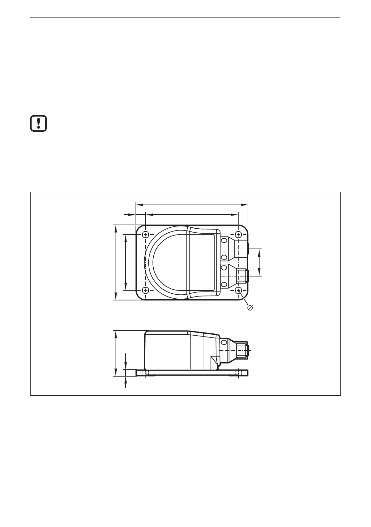
5 Scale drawing
60
36
45
4,5
90
753
22
5,3
6
Page 7

Inclination sensor JN
21
12
6 Electrical connection
The inclination sensors are fitted with two round 5-pole M12 connectors (A-coded)�
The pin connection corresponds to CiA DR-303-1�
1: CAN_SHLD shield
2: CAN_V+ supply voltage 24 V DC
5
3
M12 connector CAN-In
4
5
4
3
3: CAN_GND GND
4: CAN_H H bus cable
5: CAN_L L bus cable
1: CAN_SHLD shield
2: CAN_V+ supply voltage 24 V DC
3: CAN_GND GND
4: CAN_H H bus cable
5: CAN_L L bus cable
UK
M12 socket CAN-Out
6.1 Bus termination
The inclination sensors have an internal terminating resistor → chapter SDO
register�
7 CANopen interface
The inclination sensors have a standardised CANopen interface to CiA DS-301
and a device profile to CiA DSP-410� All measured values and parameters can be
accessed via the object directory (OD)� The individual configuration can be saved
in the internal permanent memory (EEPROM)�
7.1 CANopen functions
The following CANopen functions are available:
● Two transmit data objects (TPDO1, TPDO2) in four possible operating modes:
– individual check via a remote transmit-request telegram (RTR)
– cyclical transmission per interval time
– synchronised transmission after reception of a SYNC telegram
– a service data object (default SDO)
● Error messages per emergency object (EMCY) with support of the:
– general error register
– manufacturer-specific register
– error list (pre-defined error field)
● Monitoring mechanisms heartbeat and node guarding/life guarding
7
Page 8

Inclination sensor JN
● Status and error indication via LED (to CiA DR-303-3)
● In addition to the CiA DS-301 functionality there are more manufacturer and
profile-specific characteristics:
– Setting of the node ID and the baud rate via OD
– Freely configurable limit frequency (digital filter)
7.2 Set-up
The CANopen standard CiA301 defines three possible states for sensor nodes�
Pre-operational
In the pre-operational state no PDO messages (process data) can be transmitted�
The pre-operational state is used to set the sensor parameters or as standby
mode�
Operational
In the operational state all communication services are carried out� The operational
state is used to exchange the process data while in operation�
Stopped
In the stopped state only NMT messages (network management) are possible�
This allows almost complete separation of redundant or faulty sensors from the
bus�
The master or network manager can request the sensor via NMT messages to
change the state accordingly�
Inclination sensors are shipped from ifm electronic with the node ID 10 and a baud rate of
125 Kbits/s�
7.3 Communication types of the process data object (PDO)
Individual check via a remote transmit-request telegram (RTR)
The TPDO can be checked at any time by transmitting a remote transmit-request
telegram� This is possible in all operating modes of the inclination sensor�
7.3.1 Cyclical operating mode
The cyclical transmission of the TPDO is activated if the entry 1800h/05h
(interval time in milliseconds) contains a value greater than 0� To do so, the
entry 1800h/02h (transmission type) must contain the value 254 (asynchronous,
manufacturer-specific)� In the "operational" state the inclination sensor then
cyclically transmits the TPDO1 with the set duration of time�
8
Page 9

Inclination sensor JN
7.3.2 Synchronised transmission after reception of a SYNC telegram
For the synchronised transmission CANopen provides the SYNC object at which
the TPDO1 transmits after every "nth" reception of a SYNC telegram�
Every inclination sensor has two transmit process data objects (TPDO1/2)�
The TPDO1 contains the current inclination values (longitudinal and lateral) as
16-bit values�
Byte 0 Byte 1 Byte 2 Byte 3
Inclination value longitudinal
(x axis)
OD: 6010h
Inclination value lateral
(y axis)
OD: 6020h
The second transmit process data object TPDO2 contains the inclination values as
32-bit values�
Byte 0 to Byte 3 Byte 4 to Byte 6
Inclination value longitudinal
(x axis)
OD: 6110h
Inclination value lateral
(y axis)
OD: 6120h
The resolution (6000h) of the inclination information can be configured accordingly�
For the settings see the device profile for inclination sensors 410 0x6000 –
0x9FFF� See the object directory below�
UK
9
Page 10

Inclination sensor JN
7.4 Object directory (OD)
Index Sub-
index
1000h
1001h
1003h
1005h
100Ah
1008h
1009h
100Ch
100Dh
1010h
0 Device type
0 Error register ro u8 0
Pre-defined error field
0 Number of error entries rw u32 0
1���50 Error code
0 COB ID sync message rw u32 80h
0 Software version ("xyy") const VSTR Typical
0 Product designation const VSTR JN2100
0 Hardware version const VSTR 1�0
0 Guard time
0 Life time factor rw u8 0 Yes
Save parameters
Name (parameter) Type Default value Save
const u32 4019Ah
(device profile 410, 2 axes)
ro u32 0
(oldest error at highest index)
rw u16 0 Yes
(multiple of 1 ms)
1011h
1014h
1015h
1017h
1018h
0 Highest supported sub-index r0 u32 1
1 Save all parameters
(command: "save" 65766173h)
Restore factory parameters u32
0 Highest supported sub-index r0 u32 1
1 Restore all factory parameters
(command: "load" 64616F6Ch)
0 COB ID EMCY (emergency
message)
0 Disable time between EMCY
messages
(multiple of 100 µs)
0 Heartbeat interval time
(multiple of 1 ms, 0 deactivated)
Identity object
0 Highest supported sub-index ro u8 4
1 Vendor ID ro u32 159h
rw u32 0
rw u32 0
ro u32 80h + node ID
rw u16 0 Ye s
rw u16 0 Ye s
2 Product code ro u32 Typical
3 Revision number ro u32 Typical
4 Serial number ro u32 Typical
1029h Error behaviour object
0 Number of error classes ro u8 No
1 Error behaviour rw u8 0x0
10
Page 11

Inclination sensor JN
Index Sub-
index
1800h
1801h
Transmit PDO1 communication parameters
0 Highest supported sub-index ro u8 5
1 COB ID ro u32 180h + node ID
2 Type of transmission
3 Disable time between
4 Compatibility entry rw u8 0 Yes
5 Interval time for cycl� transmission
Transmit PDO1 communication parameters
0 Highest supported sub-index ro u8 5
1 COB ID ro u32 280h + node ID
Name (parameter) Type Default value Save
rw u8 0 Yes
(synchronous/asynchronous,
manufacturer-specific )
rw u16 0
two TPDO messages
(multiple of 100 µm)
rw u16 0 Ye s
(multiple of 1 ms, 0 deactivated)
UK
1A00h
1A01h
2 Type of transmission
(synchronous/asynchronous,
manufacturer-specific )
3 Disable time between
two TPDO messages
(multiple of 100 µs)
4 Compatibility entry rw u8 0 Yes
5 Interval time for cycl� transmission
(multiple of 1 ms, 0 deactivated)
Transmit PDO1 mapping parameters (fixed mapping)
0 Highest supported sub-index ro u8 2 Yes
1 Inclination value longitudinal
(x axis)
2 Inclination value lateral
(y axis)
Transmit PDO2 mapping parameters (fixed mapping)
0 Highest supported sub-index ro u8 2 Yes
1 Inclination value longitudinal
(x axis)
rw u8 0 Yes
rw u16 0
rw u16 0 Ye s
ro u32 60100010h
ro u32 60200010h
ro u32 61100020h
2 Inclination value lateral
(y axis)
ro u32 61200020h
11
Page 12

Inclination sensor JN
Values for error behaviour
0 = pre-operational (only if current state is operational)
1 = no change of state
2 = stopped
3 �� 127 = reserved
7.4.1 Communication parameters (to CiA DS-301)
Error register (1001h)
The error register indicates the general error status of the device� Every bit stands
for an error group� If a bit is set (= 1), at least one error of this group is active at the
moment� The contents of this register are transmitted in every EMCY message�
Error groups
Bits 5���7 Bit 4 Bit 3 Bit 2 Bit 1 Bit 0
Not used Communication error
(overrun)
Temperature Voltage Not used At least one
error active
Pre-defined error field (1003h)
Every inclination sensor keeps an error list of the last five errors occurred� The
entry 1003h/00h contains the number of error entries in the error field�
All other sub-indices contain all error states occurred in chronological order with
the error last occurred being always found under sub-index 01h�
The oldest error is in the highest available sub-index (value of 1003h/00h) and is
the first to be removed from the list in the case of more than five errors� If an error
occurs, a new error entry is added to 1003h and also communicated via an EMCY
message�
Structure of an error entry
Byte 0 Byte 1 Byte 2 Byte 3 Byte 4 Byte 5 Byte 6 Byte 7
Emergency error
code
Error register
(object 1001h)
Manufacturer-specific error field
Emergency error code (hex) Description
00xx Error reset or no error
10xx Generic error
31xx Mains voltage
32xx Voltage inside the device
41xx Ambient temperature
42xx Device temperature
80xx Monitoring
81xx Communication
8110 CAN overrun (objects lost)
12
Page 13

8120 CAN in error passive mode
8130 Life guard error or heartbeat error
8140 Recovered from bus off
8150 Transmit COB ID
82xx Protocol error
8210 PDO not processed due to length error
8220 PDO length exceeded
Inclination sensor JN
90xx External error
UK
F0xx Additional functions
7.4.2 Save (1010h) and restore (1011h) parameters
Changes of parameters in the object directory are immediately active except
for the node ID (2000h) and the baud rate (2001h)� To ensure that the changed
parameters of the communication profile DS301 are active even after a reset, they
must be saved in the internal EEPROM�
By writing the command "save" (65766173h) in the entry 1010h/01h all current
parameters of the object directory DS301 are transferred to the permanent
memory� The object directory can be reset to the factory settings via the entry
1011h/01h by writing the command "load" (64616F6Ch) in this entry�
After a "reset application" (NMT command) or a hardware reset the changes
become effective� If only a "reset communication" (NMT command) is transmitted,
only the factory settings of the communication parameters become effective�
The manufacturer-specific parameters (see chapter 6�5) are automatically saved when entered
provided they differ from the current value�
After the "save" and "load" command no reset is allowed for about 1 s so that the parameters are
correctly saved in the EEPROM�
Saving device parameters in the internal EEPROM can take relatively long� For this reason the "save"
and "load" commands are immediately replied to but saving is carried out subsequently�
Type of transmission Description
1���240 Synchronous (cyclical)
Only "synchronised transmission" is possible via SYNC
254 Asynchronous, manufacturer-specific
"Cyclical operating mode" and/or "transmit if angle is changed" can
be activated via a respective configuration
13
Page 14

Inclination sensor JN
7.5 Service data object (SDO) mapping
7.5.1 System settings 0x2000 - 0x203F
SDO
index
0x2000 0x00 u8 Node ID rw x
0x2001 0x00 u16 Baud rate Kbit rw x
0x2002 0x00 u8 Flag to reset the sensor
Subindex
Type Value Unit r/w Reset
0 rw
Flag = 1 sensor reset
7.5.2 Applicative 0x2040 - 0x207F
SDO
index
0x2040 0x00 u8 Flag for quadrant correction
0x2041 0x00 u8 Flag for heating
0x2042 0x00 u8 Index teach values of the x/y/z axes
Subindex
Type Value Unit r/w Reset
rw
0: off
1: on ± 180°
2: on 0���360°
rw
Flag = 0: heating off
Flag = 1: heating on
rw
0: no change
1: set teach, relative measurement
2: reset teach, absolute measurement
0x2043 0x00 u8 FIR filter step
0: FIR deactivated
1: FIR 10 Hz
2: FIR 5 Hz
3: FIR 1 Hz
4: FIR 0�5 Hz
0x2044 0x00 u8 Angle calculation
0: perpendicular
1: Euler
2: gimbal 1X
3: gimbal 1Y
0x2045 0x00 u8 CAN 120 Ω terminating resistor
0: resistor deactivated
1: resistor activated
0x2046 0x0 u8 Set zero point of the x / y axes
0: no change
1: set zero (corresponds to the
relative measurement)
2� reset set zero (corresponds to the
absolute measurement)
rw
rw
rw
rw
14
Page 15

7.5.3 System settings 0x4000 - 0x403F
Inclination sensor JN
SDO
index
0x4004 0x00 u8 MEMS self-test
0x4004 0x01 u8 Flag to activate the self-test
0x4004 0x02 u8 Self-test register
0x2045 0x00 u8 CAN 120 Ω terminating resistor
Subindex
Type Value Unit r/w Reset
Number of sub-indices
Flag = 1
x axis pass
x axis fail
y axis pass
y axis fail
z axis pass
z axis fail
0: resistor deactivated
1: resistor activated
→
start self-test
→
bit 2 = 1
→
bit 2 = 0
→
bit 1 = 1
→
bit 1 = 0
→
bit 0 = 1
→
bit 0 = 0
7.5.4 Informative 0x4080 - 0x40BF
r
rw
r
UK
rw
SDO
index
0x4080 0x00 Integer 32MEMS temperature 1/10 °C r
0x4081 0x00 u16 Heating power mW r
Subindex
Type Value Unit r/w Reset
7.5.5 Profile-specific part (to CiA DSP-410) 0x6000 – 0x9FFF
SDO
index
0x6000 0x00 u16 Resolution
0x6010 0x00 Integer 16Longitudinal x axis Angle
0x6020 0x00 Integer 16Lateral y axis Angle
0x6110 0x00 Integer 32Longitudinal x axis Angle
Subindex
Type Value Unit r/w Reset
1d = 0�001°
10d = 0�01°
100d = 0�1°
1000d = 1�0°
1/100 °
1/100 °
1/100 °
rw
r
r
r
0x6120 0x00 Integer 32Lateral x axis Angle
1/100 °
r
15
Page 16

Inclination sensor JN
7.6 Angle definition (2044h)
To be able to adapt the inclination sensor to the different applications as easily
as possible, the measured inclination information is converted into different angle
indications� The requested angle indication is set by selecting the respective
option�
With this angle definition a sensor coordinate system is used which is defined as
follows:
– The mounting plane corresponds to the xy plane
– The z axis is perpendicular to the mounting plane
– The x direction is represented by an edge of the mounting plate which shows
in direction of the printed x arrow�
– The y axis is then perpendicular to the plane spanned by the z and x axes�
7.6.1 Perpendicular angle (0x2044 = 0)
Using the indication of the two perpendicular angles the inclination of the sensor
coordinate system towards the direction of gravitation is described�
The first provided value (inclination value longitudinal; OD: 6010h) indicates the
angle [°] which the gravitation vector spans with the yz plane� The second provided
value (inclination value lateral; OD 6020h) indicates the angle [°] between the
gravitation vector and the xz plane�
In the case of an inclination in a plane (rotation of an axis with the second axis remaining
perpendicular) the perpendicular angle and gimbal angle are always identical�
7.6.2 Euler angle (0x2044 = 1)
In this setting the two provided angle values are to be interpreted as Euler angle�
The current sensor orientation is determined by two successive rotations from the
horizontal position�
The "inclination value longitudinal" indicates the angle [°] at which the sensor was
first rotated about the sensor's x axis� The "inclination value lateral" corresponds to
the angle [°] at which the sensor was then rotated about the (inclined) z axis�
Interpretation
The first angle value corresponds to the angle between the gravitation vector and
the sensor's z axis (slope inclination, gradient angle) whereas the second angle
value indicates the direction in which the slope inclination matches the coordinate
system�
16
Page 17

Inclination sensor JN
Value range for this option
– Inclination value longitudinal (gradient angle): -90°…+90°
– Inclination value lateral (angle of direction): 0°…360°
Critical point
With a gradient angle of 0° or 180° the sensor is in a horizontal position� In this
position the second angle (angle of direction) is useless� In practice, it is to be
expected that the value of the second angle will vary very strongly even if the
sensor is virtually motionless�
7.6.3 Gimbal angle X (0x2044 = 2)
As with the Euler angle the current orientation of the sensor is described by two
successive rotations from the horizontal position�
But the current orientation now arises from a rotation about the y axis with the
angle value [°] indicated by the "inclination value longitudinal" as well as from
a rotation which then follows about the (now rotated) x axis with the angle [°]
"inclination value lateral"�
Interpretation
If you imagine the sensor as a plane whose body shows in x direction and
whose wings in y direction, the "inclination value longitudinal" corresponds to the
longitudinal inclination of the plane (pitch angle) and the "inclination value lateral"
to the bank angle (roll angle) of the plane�
Value range
– Inclination value longitudinal: -90°…90°
– Inclination value lateral: -180°…180°
UK
Critical point
With a longitudinal inclination of ± 90° ("plane" flies vertically downwards or
upwards) the roll angle makes a rotation about the gravitational axis which cannot
be detected by the inclination sensor� In this condition the "inclination value lateral"
is insignificant� In practice, the "inclination value lateral" will vary very strongly
when it is close to this condition even if there is only little movement�
7.6.4 Gimbal angle Y (0x2044 = 3)
This setting corresponds to the setting described in 7�6�3 with the difference that
the order of the two rotations is now inverted�
In this option the measured object is first rotated about its x axis with the angle [°]
"inclination value lateral"� The measured object is then rotated about the y axis
(which is now inclined) with the angle value [°] indicated by the "inclination value
longitudinal" of the sensor�
As a result of this the measured values of the gimbal angle X and the gimbal angle
Y are identical as long as the measured object is only rotated about one of the
sensor's axes� The measured values of the two options do not differ until a general
rotation is made about the two sensitivity axes�
17
Page 18

Inclination sensor JN
Explanatory example
The different angle definitions will be illustrated using a simple example� An
excavator moves up and down an embankment (illustration)� The embankment is
angled at 30°� The inclination sensor is installed so that the x axis of the sensor
shows in driving direction of the excavator�
Excavator
position
1 0° 0°
2 -30° 0° 0° 30° -30° 0° 0° -30°
3 -20° 20° 45° 30° -20° 22° -22° 20°
4 0° 30° 90° 30° 0° 30° 30° 0°
5 0° 30° 90° 30° 0° 30° 0° 30°
6 30° 0° 180° 30° 30° 0° 30° 0°
Perpendicular angle Euler Gimbal X Gimbal Y
Longitudinal Lateral Longitudinal Lateral Longitudinal Lateral Longitudinal Lateral
undefined
0° 0° 0° 0° 0°
7.7 Node ID (2000h) and baud rate (2001h)
In the case of a change node ID and baud rate do not become effective until after
a reset (reset application, reset communication or hardware reset)�
After a reset all COB IDs are recalculated and set according to the pre-defined connection set�
The following baud rates [Kbits/s] are supported: 10, 20, 50, 125, 250, 500, 800, 1000�
7.8 Limit frequency digital filter (2043h)
With the sensor it is possible to make continuously arising angle values insensitive
to external interfering vibrations�
Using a configurable filter interfering vibrations can be suppressed� The limit
frequency is individually adjustable between 0�5���25 Hz (25 Hz corresponds to a
deactivated FIR filter)� The digital filter which is implemented in the sensor is an
eighth-order Butterworth low pass filter�
Values of 0 (deactivate filter) up to 4 (0�5 Hz) are allowed�
18
Page 19

Inclination sensor JN
7.8.1 Set zero point (2046h)
To set the zero point the sensor is rotated in the requested position�
► Write the value 1 (activate set zero point) to the object 2046h (zero point x and
y axis)�
> The sensor calculates the offset to the zero point shift and saves it in the
EEPROM� From now on the offset is added to the angle�
7.8.2 Terminating resistor (2045h)
In bus topology the CANopen system is terminated with terminating resistors
(120 Ω) at the beginning and end. The terminating resistor integrated into the
sensor can be activated by writing the value 1 to the object 2045h�
7.8.3 Set teach (2042h)
UK
In principle, all provided inclination values refer to the sensor's coordinate system
xs,ys,zs which is described in chapter 7�6�
Should it not be possible to integrate the inclination sensor into the measured
object so that the coordinate system of the sensor and object match, the teach
function enables the creation of a new reference system� The new reference
system x
b,yb,zb
is defined so that its zb direction corresponds to the direction of
gravitation at the teach moment� The xb direction of the reference system results
from the projection of the xs axis of the sensor to the xbyb plane of the reference
system� The yb axis then corresponds to the direction which is perpendicular to
both the zb and the xb axis�
The result of this is that at the teach moment the xs axis must not be parallel to the direction of
gravitation� As long as the value for the SDO index 2042h is 1, all angle indications are converted into
the new reference system�
19
Page 20

Inclination sensor JN
The teach operation can, for example, be as follows:
The measured object with the non-aligned inclination sensor is brought into a
known horizontal position� In this position the teach function is carried out, thus
defining the new reference system� All provided angle values then refer to this new
reference system�
Even with an inclination sensor which is installed at an angle note that the x axis (xs axis) of the
sensor is parallel to the xbzb plane of the requested reference system�
Explanatory example
Inclination sensor installed at an angle in the
coordinate system of the workpiece� The coordinate
system of the sensor is transferred to the coordinate
system of the workpiece by teaching the sensor
when the workpiece is horizontally aligned�
The raw data of the sensor is indicated in the
coordinate system of the sensor�
In teach mode the data is converted into the
coordinate system of the workpiece�
The example shows a rotation of 30° about the y axis of the coordinate system of
the workpiece�
Perpendicular angle
without teach
Longitudinal
angle value
-13�2° -29�3° 0° 0° -45�5° -29�5° -30° 0°
Lateral
angle value
Teach mode Perpendicular angle
without teach
Longitudinal
angle value
Lateral angle
value
Longitudinal
angle value
Lateral angle
value
Teach mode
Longitudinal
angle value
Lateral angle
value
7.8.4 Quadrant correction (2040h)
Quadrant correction means an extension of the angle indication to the measuring
ranges ± 180° (corresponds to 2040h = 1) or 0���360° (corresponds to 2040h = 2)�
The following conditions apply to the different angle calculations:
Perpendicular angle: longitudinal (x) and lateral (y) are corrected
Euler: only lateral (y) is corrected
For the gimbal angle the roll angle is corrected�
Gimbal X: longitudinal x (pitch angle), lateral y (roll angle)
Gimbal Y: longitudinal x (roll angle), lateral y (pitch angle)
20
Page 21

Inclination sensor JN
7.9 Heating (2041h)
To ensure good temperature stability over the whole temperature range, the
measuring cell is regulated to a constant temperature using a PID controller� The
regulation of the heating can be deactivated by writing the value 0 to the object
2014h�
> Reduction of temperature stability
> In the operational state the current consumption drops
7.10 MEMS self-test (4004h)
UK
To check the function of the measurement axes a self-test can be carried out� To
activate the self-test the value 1 is written to the object 0x4004/01h� The self-test
takes about 2 s� After the self-test has been carried out the object 0x4004/01h
contains the value 0�
The test result is coded in a byte and can be read from the object 0x4004/02h
(self-test register)�
JN2100
00000111: The 3 least significant bits code the internal x, y, z measurement axes
JN2101
00000011: The 2 least significant bits code the internal x, y measurement axes
Bit 0: axis faulty
Bit 1: axis functional
7.11 Temperature of the measuring cell (4080h)
The temperature of the measuring cell is determined every 200 ms and updated in
the object directory� It can be read via SDO access to the object directory (in every
device state) and via TPDO� The signed 32-bit value (two's complement) indicates
the temperature in °C�
7.12 Inclination values longitudinal and lateral (6010h and 6020h)
The current angle values of the inclination axes can be accessed via SDO access
to the object directory (in every device state) and via TPDO� The conversion of the
100-fold, signed 16-bit inclination value (two's complement) is as follows:
Value of 6010h = -2370 / 100 = -23�70°
21
Page 22

Inclination sensor JN
7.13 Emergency messages
Every inclination sensor supports EMCY messages which are transmitted in the
event of sensor, temperature, hardware or guarding errors�
If one of these errors occurs, the entries in the object directory
● 1001h (error register)
● 1003h (pre-defined error field)
are updated�
After rectification of the error the device transmits an EMCY message with the
"error reset" code (0h) and the current state of the error and manufacturer status
register� The current device state ("pre-operational, operational or stopped") is not
influenced by the error states (except for guarding errors)�
7.14 Failure monitoring
As in a CANopen network the nodes do not respond regularly in the case of
an event-controlled transmission, heartbeat and node guarding/life guarding
mechanisms are available for failure monitoring�
Only one of the two monitoring methods can be used�
7.14.1 Node guarding / life guarding
Node guarding is the monitoring of one or several nodes by the NMT master�
The NMT master periodically transmits an RTR telegram to the slave to be
monitored which responds with its own status and a toggle bit�
If the status or toggle bit do not correspond to the response expected from the
guarding master or no response is given, the master assumes a slave error�
With this mechanism the node to be monitored can detect even the failure of
the guarding master�
To do so, two parameters are used� The interval time used by the guarding
master to check the sensor to be monitored is the "guard time" (100Ch)�
The second parameter is the life time factor (100Dh)� It defines a multiplicator
after which the connection is considered as interrupted�
This time is called node life time�
Node life time = guard time × life time factor
If the sensor receives no guarding request from the master within this
configured time, it assumes a master failure� It transmits an emergency
telegram and returns to the state "pre-operational"� If one of the two parameters
is "0" (default setting), the master is not monitored (no lifeguarding)�
22
Page 23

Inclination sensor JN
7.14.2 Heartbeat
Heartbeat is a failure monitoring mechanism which needs no RTR telegrams�
The sensor cyclically transmits a heartbeat message which contains the device
status� The master can monitor these telegrams� Heartbeat is activated as soon
as a value greater than "0" is entered in the register heartbeat interval time
(1017h)�
Heartbeat has a considerable influence on the bus load of the CANopen network - but generates a
bus load which is only half as high as node guarding / life guarding�
7.15 COB IDs
The CAN identifiers of the communication objects are determined according
to the pre-defined connection set with every reset (communication, application
and hardware reset) depending on the set node ID (2000h)�
UK
Communication object Calculation of the COB ID Default value (node ID = 10)
NMT0 h 0h
SYNC 80h 80h
EMCY 80h + node ID 8Ah
TPDO1 180h + node ID 18Ah
Default SDO
(Client
Heartbeat 700h + node ID 70Ah
→
server)
580h + node ID 58Ah
7.16 Status LED (to CiA DR-303-3)
The integrated LEDs indicate the current device status (Run LED, green) and CAN
communication errors (error LED, red)�
LED Description
Green
Off The device is in the state "reset" or no power supply is available
Flashing The device is in the state "pre-operational"
Brief lighting once The device is in the state "stopped"
On The device is in the state "operational"
Red
Off No error
Brief lighting once Error counter
The CAN controller has reached or exceeded its warning limit
Brief lighting twice The device has detected the failure of the guarding master
(node guard event)
On The device is in the state "bus off"
23
Page 24

Inclination sensor JN
8 Maintenance, repair and disposal
The unit is maintenance-free�
► Dispose of the device in accordance with the national environmental
regulations�
9 Approvals/standards
The EC declaration of conformity and approvals can be found at:
www.ifm.com → Data sheet search → JN210x.
24
Page 25

Inclination sensor JN
UK
25
 Loading...