

Page 1
Operating instructions
Electronic rising stem valve sensor
IX5030
UK
704770 / 00 04 / 2010
Page 2

Contents
1 Preliminary note ���������������������������������������������������������������������������������������������������3
1�1 Symbols used ������������������������������������������������������������������������������������������������3
2 Functions and features ����������������������������������������������������������������������������������������4
2�1 Permissible shapes and dimensions of the target �����������������������������������������5
2�2 Non-permissible shapes and dimensions of the target ����������������������������������5
3 Function description���������������������������������������������������������������������������������������������6
3�1 Application example ���������������������������������������������������������������������������������������6
4 Installation������������������������������������������������������������������������������������������������������������7
5 Electrical connection ��������������������������������������������������������������������������������������������8
5�1 Assignment of the data bits ���������������������������������������������������������������������������8
6 Operation �������������������������������������������������������������������������������������������������������������9
7 Programming �������������������������������������������������������������������������������������������������������9
7�1 Programming overview ����������������������������������������������������������������������������������9
7�2 Adjustment of the valve positions of valves with 2 operating positions ������� 11
7�3 Adjustment of the valve positions of valves with 3 operating positions �������12
7�4 Locking / unlocking ���������������������������������������������������������������������������������������13
8 Set-up / operation �����������������������������������������������������������������������������������������������13
8�1 Indication by LED for the different operating modes������������������������������������13
9 Error messages �������������������������������������������������������������������������������������������������15
10 Scale drawing ��������������������������������������������������������������������������������������������������16
2
Page 3

1 Preliminary note
1.1 Symbols used
► Instruction
> Reaction, result
→ Cross-reference
Important note
Non-compliance can result in malfunction or interference�
Information
Supplementary note�
UK
3
Page 4
2 Functions and features
The rising stem valve sensor IX5030 is a continuous absolute linear measurement
system with a measuring stroke of 80 mm� The sensor is used for position
feedback for rising stem valves� For position detection three programmable switch
points can be freely selected in the measuring range� The position is signalled
visually by 3 LEDs�
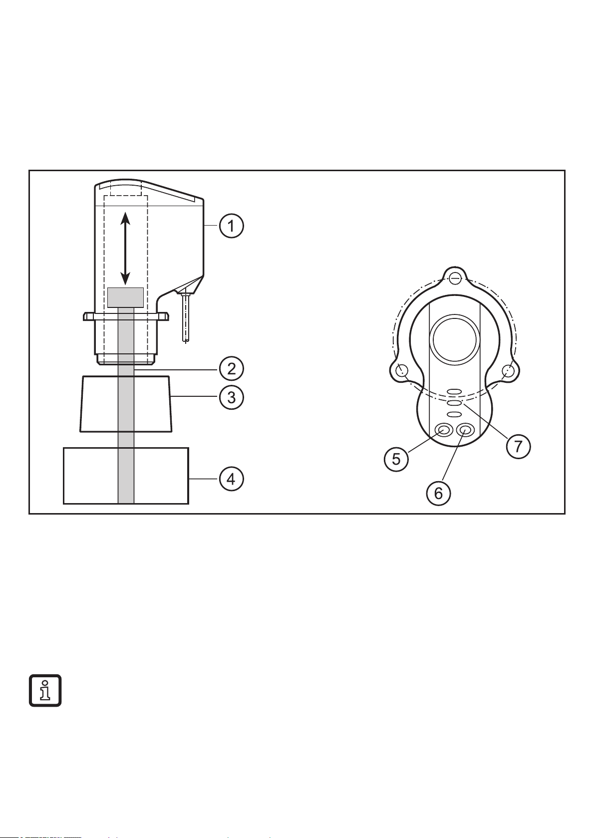
sensor
valve spindle with target
adapter / fixture
actuator of the valve
position button
Teach button
5 LEDs (open, close, seat, AS-i voltage, error)
The rising stem valve sensor IX5030 can be adapted to different valve
types� The instructions in the chapter Installation are to be observed when
designing the adapters and the fixtures�
4
Page 5
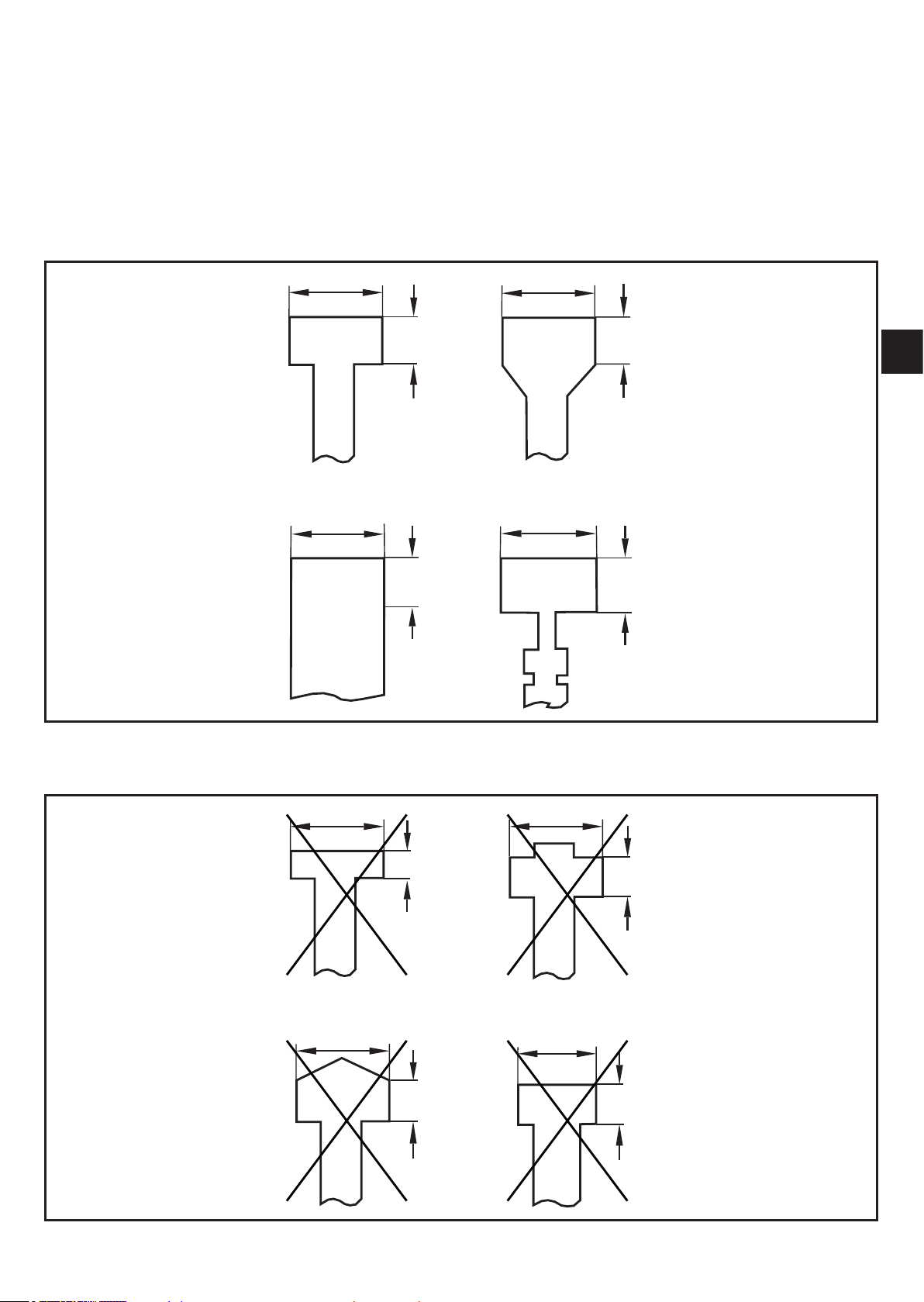
The valve spindle to be measured must have the following characteristics:
• Diameter 24 mm (tolerance: ± 0�05 mm), height at least 10 mm
• The end surface must be flat
• Material: stainless steel to DIN 17440, material number 316L / 1�4404
2.1 Permissible shapes and dimensions of the target
Ø24mm
10mm
Ø24mm Ø24mm
10mm
Ø24mm
10mm
15mm
UK
2.2 Non-permissible shapes and dimensions of the target
Ø24mm
5mm
Ø24mm
10mm
Ø24mm
10mm
Ø18mm
10mm
5
Page 6
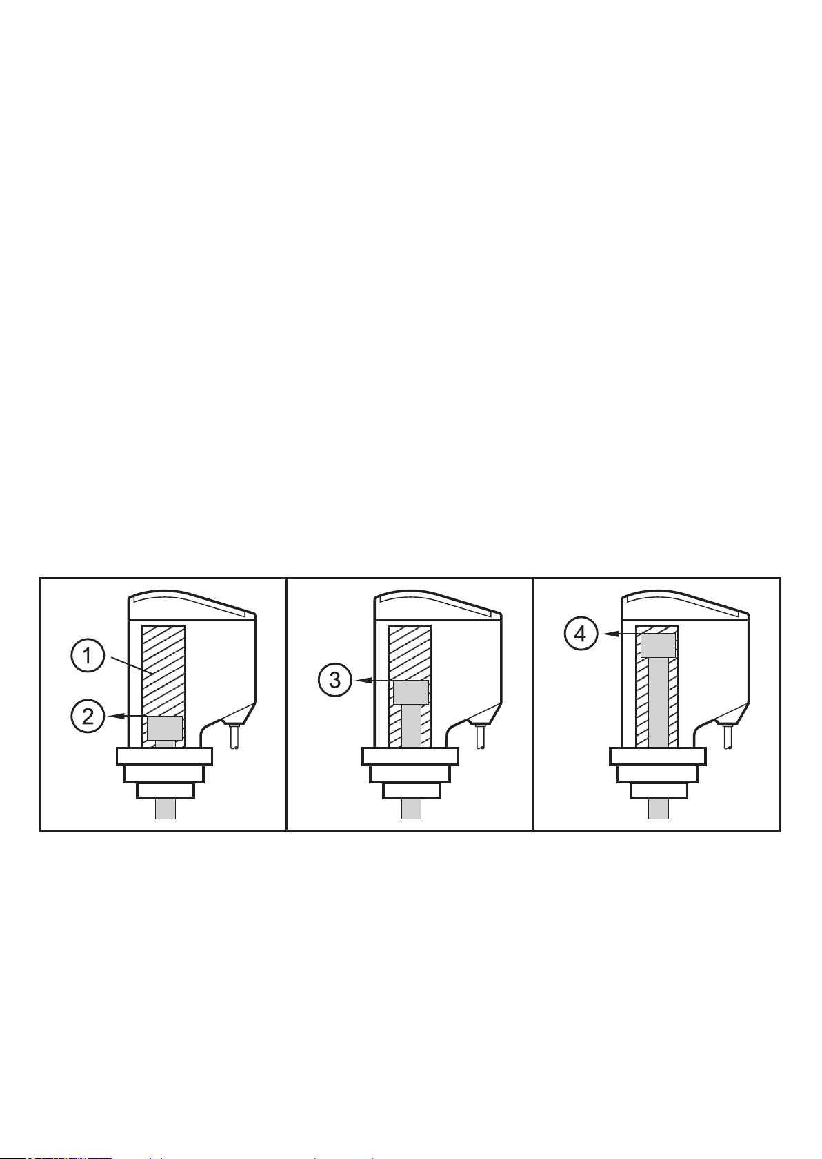
3 Function description
• The sensor measures the upper edge of the valve spindle
• Non-contact and wear-free detection of the valve positions: closed (close),
open (open) and the position for seat lift (seat) during the cleaning process�
• It is also possible to monitor the state of the valve seals instead of the seat lift�
Due to the high resolution of 0�2 mm even slight changes can be detected�
• Easy and time-saving adjustment by "teaching" (reading) the valve positions�
The taught valve positions are automatically assigned certain switching
characteristics of the three outputs, several operating modes are available (see
chapters Programming and Set-up)�
• Monitored stroke (detection zone) 80 mm� The condition "valve spindle outside
detection zone" is indicated�
• After adjustment the unit can be electronically locked to prevent unauthorised
manipulation�
3.1 Application example
closed* seat lift open*
Active detection range of
the sensor
Closed position is taught
Position seat lift is taughtOpen position is taught
* The valve positions closed and open may also be reversed�
6
Page 7

4 Installation
Place the sensor (1) on the valve spindle
(2) until the limit stop in a suitable fixture /
adapter (3)�
Fix the sensor to the 3-hole flange (3) by
means of the included fixing screws (6)�
The sensor (1) must either be integrated into
a valve top or correctly fitted to the actuator
(4) by means of a suitable adapter (3)�
If necessary adapt the length of the valve
spindle to the measuring range�
UK
7
Page 8

Ensure a tight and secure fit�
1
Make sure that no metallic components
are in the immediate vicinity of the
sensor or approach the sensor during
operation (especially no metal rings which
enclose the sensor)! This might affect the
functioning of the sensor�
Fixing elements such as screws, clamps
and similar small metal parts (< 20 x 20 x
30 mm) have no impact on the sensor� For
safe functioning the adapter (3) must be
made of plastic�
A = metallic objects
x = min� 10 mm
y = min� 46�5 mm
5 Electrical connection
The unit must be connected by a qualified electrician� The national and
international regulations for the installation of electrical equipment must be
adhered to�
Disconnect power before connecting
the unit as follows:
3
5.1 Assignment of the data bits
AS-i+
AS-i
Data bit D0 D1 D2 D3
Description close seat open not used
state = 0 plunger outside
the 'close' zone
state = 1 plunger inside
the 'close' zone
plunger outside
the 'seat' zone
plunger inside the
'seat' zone
plunger outside
the 'open' zone
the 'open' zone
plunger inside
default value
-
8
Page 9

6 Operation
The sensor is operated via the pushbuttons
Pos� and Teach� To do so, press the buttons
with a blunt object�
Sharp edges may damage the
buttons!
openclose
seat
Powerfault
UK
7 Programming
7.1 Programming overview
Teach mode
P
yes
no
Run mode
P
>2s
adjust close
yes
position?
no
P
Check
P
>5s
TT
adjust seat
adjust open
position?
position?
no
P
P: actuate Pos� button T: actuate Teach button
T
yes
9
Page 10

After installation you have to adjust the unit to the valve positions to be detected�
You can carry out the adjustment process in a variable and time-saving way� First
clarify which type of valve you have� The sensor differentiates between two types:
1� Valves with 2 operating positions (closed and open)
2� Valves with 3 operating positions (closed, open and a position inbetween for
the seat lift)
For valves with 2 operating positions the wear of the valve seals is monitored
automatically� This function is not possible for the detection of three operating
positions�
The programming options are shown in the programming overview ( → 7�1) After
entering into the programming mode (Teach mode) the unit first expects the
adjustment of the closed position (close)�
However, you can also start with any other position�
If e�g� the valve is already in the open position (open), just start adjusting this
position� To do so, press the Pos� button 2 x, thus skipping the adjustment of the
closed and the seat position� You can carry out the skipped adjustment steps
afterwards�
Skipping a current programming step is also required for example if you use
valves with only 2 operating positions for which the position of the seat lift is not
available� If the position seat lift is not adjusted ("taught") the unit automatically
passes into an operating mode which monitors the wear of the valve seals (see
also chapter Set-up / operation)�
The unit cannot be taught via the AS-i bus�
10
Page 11

7.2 Adjustment of the valve positions of valves with 2
operating positions
Press the Pos� button for at
1
least 2 s�
Put the valve into the
2
closed position and press the
Teach button�
Press the Pos� button once,
3
thus skipping the current
programming step� This is
necessary because your
valve does not have the
position seat lift�
All LEDs flash 2 x simultaneously� The unit is
in the programming mode� Then only the LED
"close" is lit�
The unit is now ready for the adjustment of the
closed position (close)�
The LED "close" goes out and the LED "seat"
lights� The unit has stored the closed position
and is now ready for the adjustment of the
position seat lift (seat)�
The LED "open" lights� The unit is now ready
for the adjustment of the open position�
UK
Put the valve into the open
4
position and press the Teach
button�
Press the Pos� button for at
5
least 5 s� After 5 s the LED
"open" flashes at about 2 Hz�
The LED "open" goes out and the LED "close"
lights again� The unit has now stored all
positions�
After releasing all stored measured values
are checked� If no errors are detected all
LEDs simultaneously flash 2 x� The unit
automatically quits the programming mode
and immediately passes into the operating
mode�
If, however, an error is found during the
check the LED "close" flashes at about 8 Hz�
Acknowledge the error message by pressing
the Pos� button and repeat the adjustment�
11
Page 12

7.3 Adjustment of the valve positions of valves with 3
operating positions
Press the Pos� button for at
1
least 2 s�
Put the valve into the
2
closed position and press
the Teach button�
Put the valve into the position
3
seat lift and press the Teach
button�
Put the valve into the open
4
position and press the Teach
All LEDs flash 2 x simultaneously� The unit is
in the programming mode� Then only the LED
"close" is lit�
The unit is now ready for the adjustment of the
closed position (close)�
The LED "close" goes out and the LED "seat"
lights� The unit has stored the closed position
and is now ready for the adjustment of the
position seat lift (seat)�
The LED "seat" goes out and the LED "open"
lights� The unit has stored the position seat
lift and is now ready for the adjustment of the
open position (open)�
The LED "open" goes out and the LED "close"
lights again� The unit has now stored all
button�
Press the Pos� button for at
5
least 5 s� After 5 s the LED
"open" flashes at about 2 Hz�
positions�
After releasing all stored measured values
are checked� If no errors are detected all
LEDs simultaneously flash 2 x� The unit
automatically quits the programming mode
and immediately passes into the operating
mode�
If, however, an error is found during the
check the LED "close" flashes at about 8 Hz�
Acknowledge the error message by pressing
the Pos� button and repeat the adjustment�
12
Page 13

7.4 Locking / unlocking
The unit can be locked electronically to prevent unintentional operations�
Press both setting pushbuttons simultaneously for at least 10 s in the operating
mode� After 10 s each LED lights briefly one after the other� Then the unit is locked
or unlocked�
In the locked state operations are ignored�
On delivery: unlocked�
8 Set-up / operation
After installation, wiring and adjustment check whether the unit operates correctly�
If possible, put the valve into all available positions and check whether the unit
switches correctly and whether the operations are correctly indicated by the LEDs�
8.1 Indication by LED for the different operating modes
The sensor has 3 operating modes which the sensor automatically generates
depending on the programming�
• Mode A:
For valves with 2 operating positions� The wear of the valve seals is monitored�
• Mode B:
For valves with 3 operating positions� The position seat lift (seat) is between
the positions closed and open�
• Mode C:
UK
For valves with 3 operating positions� The position seat lift (seat) is outside the
positions closed and open�
13
Page 14

80
Pos [mm]
70
60
50
40
30
Teach
Mode A Mode B Mode C
open + seat
open
Teach Teach
open
seat
open
close
20
10
0
LED "close" flashes at 8 Hz�
= valve spindle at the limit or outside the detection range
close
close + seat
close
seat
• The respective LED at the zones marked in grey lights, at the same time the
output corresponding to this state is closed (switched)� At the zones marked in
white and outside the detection area (zones hatched diagonally) all outputs are
open (not switched)�
• All modes are also possible in inverted form, i�e� the open and closed positions
can be inverted� The sensor detects this automatically, the assignment of the
switching characteristics is carried out automatically�
• The open and closed zones are placed nearly at the limits, i�e� the Teach
positions are at the limit of the zones� The seat zones are placed in the middle,
i�e� symmetrically around the Teach position�
• To monitor the seal the open and closed zones in the mode A are only 1�5
mm� The zones open+seat and close+seat are adjacent� In these zones the
14
Page 15

outputs "open" and "seat" and the outputs "close" and "seat" are switched
simultaneously� This signals wear of the valve seal!!
• In the mode A only 2 valve positions are to be adjusted, the positions closed
and open� The adjustment of the seat lift must not be carried out, please skip
this program step by pressing the Pos� button� The sensor then automatically
generates the mode A�
9 Error messages
LED Fault description Measure
close Flashes at 8 Hz directly after
leaving the programming mode =
adjustment error!
Taught position values are not within
the detection range or positions are not
during adjustment
close Flashes at 8 Hz = target is at the limit or
close Flashes at 8 Hz = fault in the electronics�
during operation
allowed or plausible�
outside the detection range or the target
is in non defined zones (white zones, see
above diagram) for longer than 20 s�
Contrary to the other error messages this
error message cannot be acknowledged
or terminated�
UK
► Acknowledge the error
message by pressing the
Pos� button and repeat the
adjustment�
► Check the position of the
valve�
► Replace the sensor�
15
Page 16

10 Scale drawing
65
110
99,6
26,5
88,6
80
4,5
15,5
26
6,2
52
34,8
38
3
4
Max� spindle stroke
Measuring distance
Initial value of the measuring range (zero point)
Programming buttons (Pos� / Teach)
LED green = open / LED red = close
LED green = AS-i voltage / LED red = error
LED yellow = seat
16
4,3
Page 17

UK
17
 Loading...