

IFM Electronic EC2100 Short Instructions

Short instructions
CAN BusTester
Mobile device for the analysis
of CAN networks
EC2100
UK
7390922 / 00 05 / 2012

CAN BusTester EC2100
Contents
1 Preliminary note � � � � � � � � � � � � � � � � � � � � � � � � � � � � � � � � � � � � � � � � � � � � � � � � � 4
1�1 Symbols used� � � � � � � � � � � � � � � � � � � � � � � � � � � � � � � � � � � � � � � � � � � � � � � 4
1�2 Warning signs used � � � � � � � � � � � � � � � � � � � � � � � � � � � � � � � � � � � � � � � � � � 4
2 Safety instructions � � � � � � � � � � � � � � � � � � � � � � � � � � � � � � � � � � � � � � � � � � � � � � � 4
3 Functions and features � � � � � � � � � � � � � � � � � � � � � � � � � � � � � � � � � � � � � � � � � � � � 5
3�1 Features at a glance� � � � � � � � � � � � � � � � � � � � � � � � � � � � � � � � � � � � � � � � � � 5
3�2 Help and additional information � � � � � � � � � � � � � � � � � � � � � � � � � � � � � � � � � 5
4 Installation� � � � � � � � � � � � � � � � � � � � � � � � � � � � � � � � � � � � � � � � � � � � � � � � � � � � � � 5
5 Electrical connection� � � � � � � � � � � � � � � � � � � � � � � � � � � � � � � � � � � � � � � � � � � � � � 6
5�1 General electrical connection � � � � � � � � � � � � � � � � � � � � � � � � � � � � � � � � � � � 6
5�2 Operating voltage � � � � � � � � � � � � � � � � � � � � � � � � � � � � � � � � � � � � � � � � � � � � 6
5�2�1 Battery charging� � � � � � � � � � � � � � � � � � � � � � � � � � � � � � � � � � � � � � � � � 6
5�2�2 Battery life � � � � � � � � � � � � � � � � � � � � � � � � � � � � � � � � � � � � � � � � � � � � � 6
5�3 CAN interface (terminating resistor) � � � � � � � � � � � � � � � � � � � � � � � � � � � � � � 6
5�4 Ethernet interface � � � � � � � � � � � � � � � � � � � � � � � � � � � � � � � � � � � � � � � � � � � 6
5�5 USB interfaces � � � � � � � � � � � � � � � � � � � � � � � � � � � � � � � � � � � � � � � � � � � � � � 7
6 Operating and display elements � � � � � � � � � � � � � � � � � � � � � � � � � � � � � � � � � � � � � 8
6�1 Display � � � � � � � � � � � � � � � � � � � � � � � � � � � � � � � � � � � � � � � � � � � � � � � � � � � � 8
6�2 Operating elements � � � � � � � � � � � � � � � � � � � � � � � � � � � � � � � � � � � � � � � � � � 8
7 Setup � � � � � � � � � � � � � � � � � � � � � � � � � � � � � � � � � � � � � � � � � � � � � � � � � � � � � � � � � 9
7�1 General notes� � � � � � � � � � � � � � � � � � � � � � � � � � � � � � � � � � � � � � � � � � � � � � � 9
7�1�1 Notes on the touch screen � � � � � � � � � � � � � � � � � � � � � � � � � � � � � � � � � 9
7�2 Switch on the device � � � � � � � � � � � � � � � � � � � � � � � � � � � � � � � � � � � � � � � � 10
7�3 Switch off the device � � � � � � � � � � � � � � � � � � � � � � � � � � � � � � � � � � � � � � � � 10
7�3�1 Switch off via the ON/OFF key� � � � � � � � � � � � � � � � � � � � � � � � � � � � � 10
7�3�2 Switch off via softkey � � � � � � � � � � � � � � � � � � � � � � � � � � � � � � � � � � � � 10
7�4 Set the screen contrast � � � � � � � � � � � � � � � � � � � � � � � � � � � � � � � � � � � � � � �11
7�5 Switch the screen on/off � � � � � � � � � � � � � � � � � � � � � � � � � � � � � � � � � � � � � � �11
7�6 Language selection � � � � � � � � � � � � � � � � � � � � � � � � � � � � � � � � � � � � � � � � � �11
8 Operation � � � � � � � � � � � � � � � � � � � � � � � � � � � � � � � � � � � � � � � � � � � � � � � � � � � � � 12
8�1 User interface � � � � � � � � � � � � � � � � � � � � � � � � � � � � � � � � � � � � � � � � � � � � � � 12
8�1�1 Main menu � � � � � � � � � � � � � � � � � � � � � � � � � � � � � � � � � � � � � � � � � � � � 12
8�1�2 Configuration menu � � � � � � � � � � � � � � � � � � � � � � � � � � � � � � � � � � � � � 13
8�1�3 Status Line � � � � � � � � � � � � � � � � � � � � � � � � � � � � � � � � � � � � � � � � � � � � 13
8�2 The most important function elements of the measuring setup � � � � � � � � 14
8�2�1 CANopen Manager (hardware) � � � � � � � � � � � � � � � � � � � � � � � � � � � � 14
8�2�2 CANopen Manager � � � � � � � � � � � � � � � � � � � � � � � � � � � � � � � � � � � � � 16
8�2�3 Trace panels (RawCAN and CANopen)� � � � � � � � � � � � � � � � � � � � � � 18
8�3 Further function elements of the measurement setup � � � � � � � � � � � � � � � 20
9 Technical data� � � � � � � � � � � � � � � � � � � � � � � � � � � � � � � � � � � � � � � � � � � � � � � � � � 22
2

CAN BusTester EC2100
10 Maintenance, repair and disposal� � � � � � � � � � � � � � � � � � � � � � � � � � � � � � � � � � 24
10�1 Device update � � � � � � � � � � � � � � � � � � � � � � � � � � � � � � � � � � � � � � � � � � � � 24
10�2 Cleaning the display surface � � � � � � � � � � � � � � � � � � � � � � � � � � � � � � � � � 24
10�3 Cleaning the housing surface� � � � � � � � � � � � � � � � � � � � � � � � � � � � � � � � � 25
10�4 Repair� � � � � � � � � � � � � � � � � � � � � � � � � � � � � � � � � � � � � � � � � � � � � � � � � � � 25
10�5 Change of battery� � � � � � � � � � � � � � � � � � � � � � � � � � � � � � � � � � � � � � � � � � 25
10�6 Disposal � � � � � � � � � � � � � � � � � � � � � � � � � � � � � � � � � � � � � � � � � � � � � � � � � 25
UK
This document is the original instructions�
Licences and trademarks
Microsoft
All trademarks and company names are subject to the copyright of the respective companies�
®
, Windows®, Windows XP®, and Windows Vista® are registered trademarks of Microsoft Corporation�
3
CAN BusTester EC2100
1 Preliminary note
1.1 Symbols used
► Instructions
> Reaction, result
[…] Designation of pushbuttons, buttons or indications
→ Cross-reference
Important note
Non-compliance can result in malfunction or interference�
Information
Supplementary note
1.2 Warning signs used
WARNING
Warning of serious personal injury�Death or serious irreversible injuries may
result�
CAUTION
Warning of personal injury�Slight reversible injuries may result�
NOTE
Warning of damage to property�
2 Safety instructions
These instructions are part of the device� They contain information and illustrations
about the correct handling of the device and must be read before installation or
use�
Observe the operating instructions�
Non-observance of the instructions, operation which is not in accordance with use
as prescribed below, wrong installation or incorrect handling can affect the safety
of operators and machinery�
The installation and connection must comply with the applicable national and
international standards� Responsibility lies with the person installing the device�
Only the signals indicated in the technical data or on the device label may be
supplied to the connections or wires�
4

CAN BusTester EC2100
3 Functions and features
The device is a mobile industrial PC specially developed for diagnostic purposes in
11-bit or 29-bit identifier CAN networks�
In conjunction with the "CANexplorer Touch" program, it ensures the CAN bus
observation and the analysis of CAN data by means of layer-7 protocols such as
CANopen or SAE J1939�
WARNING
The device is intended for use indoors or in closed vehicles� It must not be
operated in hazardous areas�
3.1 Features at a glance
● 7" TFT touch screen
● Operating system Windows XP Embedded
● CANexplorer 4 with application CANexplorer Touch, preinstalled
● CAN interface with CANopen and SAE J 1939 protocol
● Ethernet and USB interfaces
● CAN data transfer cyclical, blockwise or manual
● Display of the bus load, voltage level, baud rate and error frames
● Filter and trigger functions
3.2 Help and additional information
These short instructions describe the main steps for the connection, setup and
operation of the device�For detailed information we refer you to the context-
sensitive help (→ 8.1.1 Main menu).
UK
4 Installation
The device is designed for mobile applications� It is supplied and used without any
mounting accessories�
5
CAN BusTester EC2100
5 Electrical connection
5.1 General electrical connection
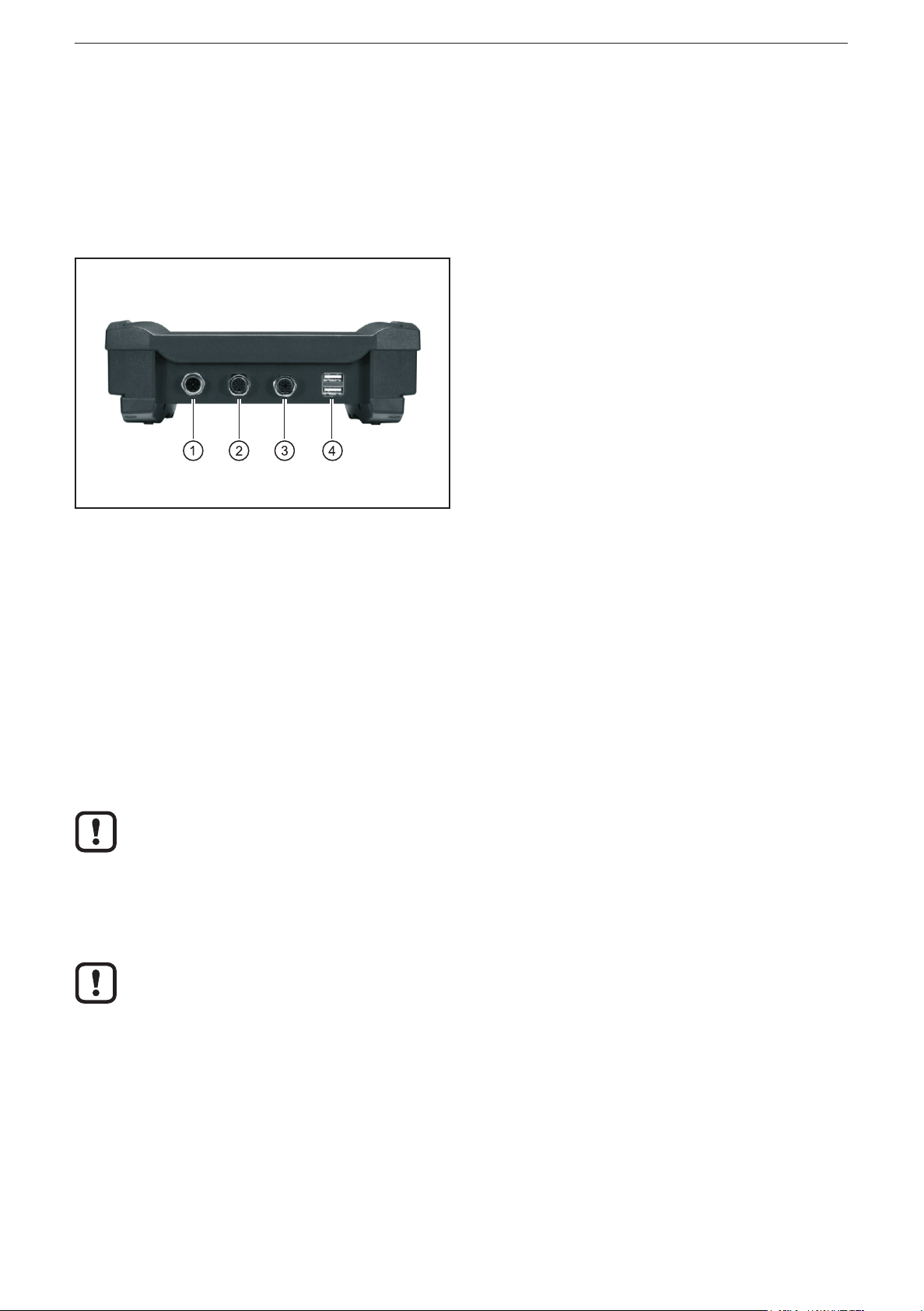
The interfaces to external systems are at the bottom of the device�
CAN bus, USB devices and the LAN network are automatically recognised when
they are connected�
1: Supply, CAN (M12 connector, 5 poles)
2: Supply, CAN (M12 socket, 5 poles)
3: Ethernet (M12 socket, 4 poles, D-coded)
4: USB (2 x type A)
Bottom of the device
Wiring of the connectors (→ 9 Technical data)
5.2 Operating voltage
The supply voltage rate is 10���32 V DC� Supply is effected via the 5-pole M12
connector (1)�
5.2.1 Battery charging
As soon as an external voltage supply is applied, the integrated rechargeable
batteries are charged�
With first setup please note that the device is operated until the integrated
rechargeable batteries are fully charged�
5.2.2 Battery life
When the supply voltage is switched off, battery operation starts at once�
The integrated rechargeable batteries are used as a buffer for short-time
voltage interruptions (≤ 10 min). During operation the voltage is supplied, for
example, via the on-board voltage of a vehicle�
5.3 CAN interface (terminating resistor)
To be able to loop into existing CAN networks the CAN interfaces do not have any
terminating resistor�
5.4 Ethernet interface
► Use a shielded CAT5 cable�
STP, shielded twisted pair, according to EIA/TIA-568� Max� length 100 m
6

CAN BusTester EC2100
The max� cable length depends for example on the bus topology, the
selected operating mode (10/100 Mbits/s) or the quality of the connectors�
► Use screened connector housings and connect the screen of the Ethernet
cable to the connector housing�
► Do not lay the Ethernet cable in parallel to live cables�
Interference due to external influences
Faulty or insufficient radio interference suppressors in other electrical
equipment, such as inverters or generators, as well as voltage fluctuations
when switching on/off electric loads may lead to problems with the data
transmission�
5.5 USB interfaces
The USB interfaces are used for the temporary connection of a USB flash drive or
an external keyboard�
UK
7
CAN BusTester EC2100
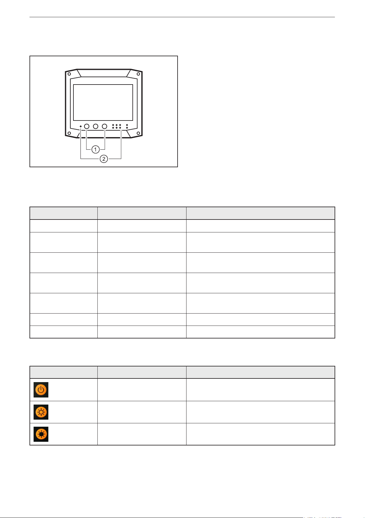
6 Operating and display elements
1: Pushbuttons
2: LEDs
Operating and display elements
6.1 Display
LED Status Description
PWR On External voltage supply applied
HDD Flashing Device is switched on
Data access to internal memory
BATTERY Flashing
On
LAN-LINK
LAN-ACT
CAN-Rx
CAN-Tx
WLAN - No function
BT - No function
ON
Flashing
Flashing Communication via CAN
Battery is charging
Battery is completely charged
Device is connected to Ethernet
Communication via Ethernet
6.2 Operating elements
Button Description Description
ON/OFF Switching the device on and off
Brighter Regulation of the display lighting
Darker Regulation of the display lighting
8
 Loading...