

Page 1
Installation Instructions
UK
E70188 / E70200
UK
701371/01 04/2001
Page 2
Function and features
The PAAS module is used to open an AS-i spur or for additional voltage supply •
(current load 8 A).
With the PAAS M12 module the AS-i voltage and external voltage can be •
tapped via the M12 socket (current load 4 A).
Mounting
Disconnect the installation.
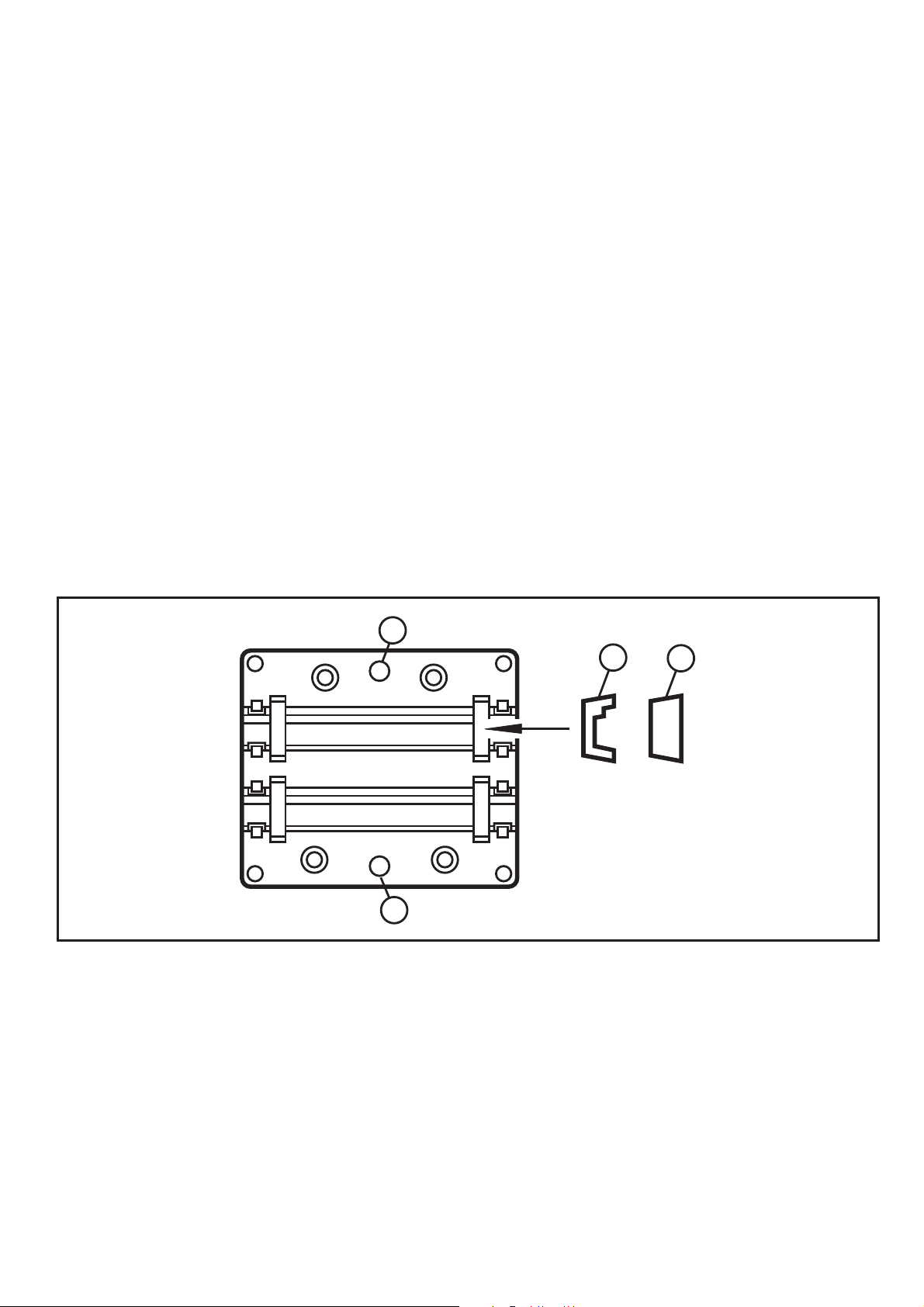
Mounting of the lower part
Use a plane mounting surface. The module must lie on the mounting surface
with its whole bottom. Fix the lower part onto the mounting surface (mounting
holes (1)). The fixing screws are not supplied.
Insert the profile seals (3) into the module lower part. If the module is positioned
at the end of the cable line, the terminating seals (4) must be inserted into the
module lower part to ensure the protection rating IP65.
1
3
Line 1
Line 2
1
4
Version PAAS
Insert the incoming AS-i flat cable (yellow or black for the external voltage supply)
into the cable duct „Line 1“ and the outgoing AS-i flat cable (yellow or black) into
the cable duct „Line 2“. Correctly position the cables into the profile slot. The two
cable ducts are electrically connected in parallel.
With the PAAS version always use two AS-i flat cables of the same colour (yellow /
yellow or black / black) in line 1 and line 2.
2
Page 3

Connection PAAS M12
M12 socket Pin
AS-i + 1
0V 2
AS-i - 3
2
2 1 2
1 2
PEPE
1
24
3
5
UK
+24 V 4
PE 5
Version PAAS M12
Insert the AS-i flat cable (yellow) into the cable duct „Line 1“ and the 24 V flat
cable (black) into the cable duct „Line 2“. Correctly position the cables into the
profile slot. Connect the PE wire to the screws (2) with earth springs.
Mounting of the upper part
Place the upper part and tighten the screws (2) (screws are supplied).
Fixing upper part/lower part
2 1 2
2 1 2
3
 Loading...