

Page 1
Operating instructions
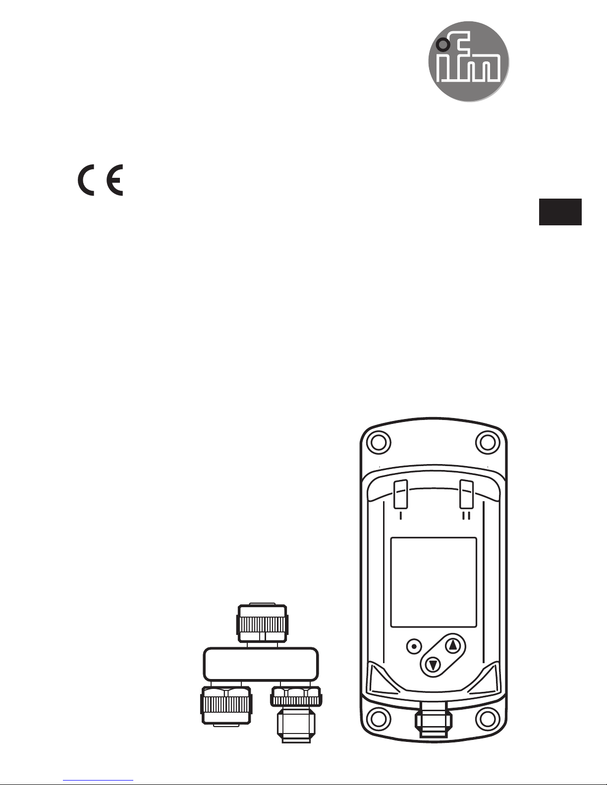
IO-Link INLINE DISPLAY 1.44"
E30430
80235800 / 00 02 / 2017
UK
Page 2

2
Contents
1 Safety instructions ...............................................................................................2
2 Functions and features .......................................................................................3
3 Function ............................................................................................................... 4
4 Installation ...........................................................................................................4
5 Electrical connection ............................................................................................ 4
6 Operating and display elements ..........................................................................5
7 Set-up ..................................................................................................................6
7.1 Device catalogue update ...............................................................................6
8 Menu .................................................................................................................... 6
9 Parameter setting ................................................................................................8
9.1 Parameter setting in general .........................................................................8
10 Troubleshooting .................................................................................................8
Technical data, approvals, accessories and further information at
www.ifm.com.
1 Safety instructions
• Read this document before setting up the product and keep it during the entire
service life.
• The product must be suitable for the corresponding applications and environmental conditions without any restrictions.
• Only use the product for its intended purpose (→ 2 Functions and features).
• If the operating instructions or the technical data are not adhered to, personal
injury and/or damage to property may occur.
• The manufacturer assumes no liability or warranty for any consequences caused by tampering with the product or incorrect use by the operator.
• Installation, electrical connection, set-up, operation and maintenance of the unit
must be carried out by qualified personnel authorised by the machine operator.
• Protect units and cables against damage.
Page 3
3
UK
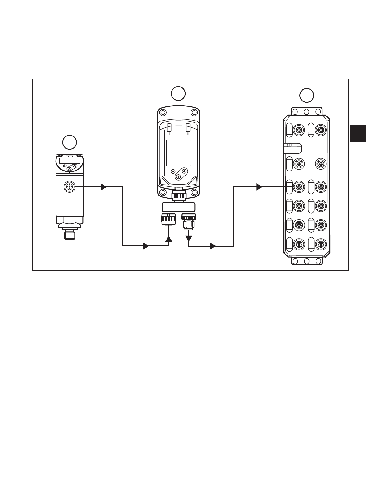
2 Functions and features
The IO-Link INLINE DISPLAY is used for indicating process values and the corresponding information from a connected IO-Link sensor.
The parameters of the connected sensor cannot be set via the INLINE DISPLAY.
3
1
2
Example of a system integration
1: IO-Link sensor
2: IO-Link INLINE DISPLAY
3: IO-Link master
Page 4

4
3 Function
During operation, the device determines the process data that is cyclically transmitted by the sensor and indicates it on the display and as LED status.
4 Installation
► Insert the unit into the system so that no mechanical forces are exerted on the
housing.
► For installation use the supplied accessories.
5 Electrical connection
The camera must be connected by a qualified electrician.
The national and international regulations for the installation of electrical
equipment must be adhered to.
Voltage supply according to EN 50178, SELV, PELV.
► Disconnect power.
► Connect the unit as follows:
43
2 1
BK: black
BN: brown
BU: blue
WH: white
BN
WH
BK
BU
4
1
3
2
OUT2
L
+
L
OUT1
Colours to DIN EN 60947-5-2
Pin 1 L+
Pin 3 L-
Pin 2 (OUT2) IO-Link communication interface to the device
Pin 4 (OUT1) IO-Link communication interface from the master
Page 5

5
UK
6 Operating and display elements
3
1 2
4
5
1, 2: Indicator LEDs
• LED 1 = switching status OUT1
(is on when output 1 on the connected device is switched)
• LED 2 = switching status OUT2
(is on when output 2 on the connected device is switched)
3: TFT display
• Indication of current process values
• Indication of the parameters and parameter values.
4: Buttons up [▲] and down [▼]
• Select parameters
• Change parameter values (hold button pressed)
• Switch between process value display and status display in the normal operating mode
(RUN mode)
• Locking / Unlocking (buttons pressed simultaneously > 10 seconds)
5: Button [●] = Enter
• Change from the RUN mode to the main menu
• Change to the setting mode
• Acknowledge the set parameter value
Page 6

6
7 Set-up
The device can indicate process values of ifm units. No settings are necessary.
In case the connected ifm unit cannot be displayed:
► Update the internal device catalogue (→ 7.1).
7.1 Device catalogue update
► Connect the INLINE DISPLAY with the computer using the USB IO-Link master
E30390.
► Activate the device mode in the device menu.
► Open LR DEVICE and transfer the current version of the "Catalogue update
IODD" to the device.
Depending on the size, the update of the display may take several minutes. Usually, the update takes about 1 minute.
8 Menu
Process value display (RUN mode)
EF
IO-L
DIS
_
rES
Info
DIS
diS.S
diS.B
diS.U
diS.R
PDis
EF
_
PDis
PV.1
PV.2
LED
PV.3
PV.4
Page 7

7
UK
Explanation of the main menu
PDis Opening of the lower menu level PDis.
EF Opening of the lower menu level EF.
Explanation of the process value display (PDis)
LED Switching status LEDs: ON, OFF
PV.x Process value display:
OFF = process value is not displayed
bk/wh = black or white, depending on the setting of the background ddiS.S
red = red
green = green
yellow = yellow
(x = 1...4 for the 4 process values that can be displayed)
Explanation extended functions (EF)
rES Restore factory settings
Info Device information
IO-L IO-Link communication: ON/OFF
- OFF: normal operation as passive display
- ON: parameter setting or update of the device catalogue via the IODD tool
(e.g. LR DEVICE → www.ifm.com).
When the device is started, this point is reset to OFF.
DIS Opening of the lower menu level.
Explanation display settings (DIS)
diS.S Display background schema:
dark = black
light = white
diS.U Display refresh rate: d1, d2, d3, d4, d5.
diS.R Display rotation in degrees: 0, 90, 180, 270.
diS.B Display brightness: 25, 50, 75, 100, OFF.
Page 8

8
9 Parameter setting
9.1 Parameter setting in general
1. Change from the RUN mode to the main menu [●]
2. Select the requested parameter [▲] or [▼]
3. Change to the setting mode [●]
4. Modification of the parameter value [▲] or [▼] > 1 s
5. Acknowledge the set parameter value [●]
6. Return to the RUN mode > 30 s (timeout) or press [▲] and
[▼] simultaneously until the RUN
mode is reached.
10 Troubleshooting
Display Description Type Instructions
1 ERROR Faulty units /
malfunction
Error ► Replace device
2 (off) Supply voltage too
low
Error ► Assure a voltage supply with a
sufficiently available current.
(18 … 30 V DC)
3 PARA Parameter setting
outside the valid
range.
Error 1. Save the parameter settings.
2. Restore the factory settings.
3. Enter parameters again.
PARA
invalid device
catalogue,
try catalogue
update
Device catalogue no longer up to
date.
► Reinstall device catalogue
Page 9

9
UK
Display Description Type Instructions
4 no
connection
No IO-Link
connection between
the master and the
device was found
Error • If the device is only connected
to a power supply, this status is
normal.
• If parameter IO-Link = OFF:
► Check the cable connections
and the function of the connected IO-Link participants
► If necessary, re-establish the
communication
5 invalid Invalid flag of the
process data (PDV)
is set. Indicated in the
process value line
Error The process value of the connec-
ted device is marked as invalid.
► Check the connected device.
6 unsupported
device of
vendor <xxx>
No process data
description for the
device available.
Error The connected device is not in the
device catalogue.
unknown ifm
device try
catalogue
update
Device catalogue no longer up to
date.
► Device catalogue update: De-
vice catalogue download for ifm
devices at www.ifm.com.
7 invalid
process data
description
The process data
description does not
match the communication content.
Error Process data recognition error.
► Restart the communication with
the connected device, e.g. by
disconnecting and reconnecting
the device.
Page 10

10
Display Description Type Instructions
8 Loc The setting buttons
on the unit are
locked,
Parameter change
rejected.
Warning ► Unlock the unit → 6 Operating
and display elements.
9 C.Loc Parameter setting
via pushbuttons
disabled,
parameter setting via
IO-Link communication is active.
Warning ► Wait until the parameter setting
via the remote participant is
finished.
10 S.Loc Setting buttons
locked via parameter
software,
Parameter change
rejected.
Warning ► Unlock the setting buttons via
the parameter setting software.
11 no process
data
available
No process data is
available
Warning The device is in the pre-operate
mode.
► Wait until the connection is
established.
 Loading...