

Page 1
Operating instructions
Memory Plug
E30398
704930 / 03 08 / 2018
UK
Page 2

2
Contents
1 Preliminary note ��������������������������������������������������������������������������������������������������� 3
1�1 Symbols used ������������������������������������������������������������������������������������������������3
1�2 Terms used ����������������������������������������������������������������������������������������������������4
2 Safety instructions �����������������������������������������������������������������������������������������������5
3 Factory setting �����������������������������������������������������������������������������������������������������6
4 Functions and features ����������������������������������������������������������������������������������������6
4�1 Applications without PC ���������������������������������������������������������������������������������6
4�2 Applications with IO-Link master and LR DEVICE
(software) ������������������������������������������������������������������������������������������������������� 7
4�3 Basic operating conditions �����������������������������������������������������������������������������7
5 Electrical connection �������������������������������������������������������������������������������������������� 8
6 Operation ������������������������������������������������������������������������������������������������������������� 9
6�1 Save the parameter set of a sensor once �����������������������������������������������������9
6�2 Save the parameter set of a sensor continuously ��������������������������������������10
6�3 Copy the parameter set of a sensor ����������������������������������������������������������� 11
6�4 Set the parameters of the replacement sensor �������������������������������������������12
6�5 Restore the parameter set of a sensor ��������������������������������������������������������13
6�6 Configure the memory plug via LR DEVICE ������������������������������������������������14
6�6�1 Store data on the memory plug ����������������������������������������������������������14
6�6�2 Read and edit the data stored on the memory plug ��������������������������15
6�6�3 Restore the factory setting of the memory plug ���������������������������������� 15
6�7 Operation indication �������������������������������������������������������������������������������������15
6�8 Configuration via teach button ��������������������������������������������������������������������� 16
6�9 Use the memory plug as data carrier ����������������������������������������������������������18
7 Technical data ���������������������������������������������������������������������������������������������������� 18
8 Troubleshooting �������������������������������������������������������������������������������������������������19
Page 3
3
UK
1 Preliminary note
1.1 Symbols used
► Instructions
> Reaction, result
→ Cross-reference
Important note
Non-compliance may result in malfunction or interference�
Information
Supplementary note�
LED on
LED off
LED flashes slowly (1 Hz)
LED flashes quickly (4 Hz)
LED flickers
Page 4

4
1.2 Terms used
Memory plug Plug with storage medium
Memory plug empty Setting at the factory�
No parameter set is saved in the memory plug�
The memory plug has to be connected to a sensor or a PC
system in order to save a valid parameter set�
Memory plug full A valid parameter set is available in the memory of the
memory plug�
Memory plug
transparent
The memory plug is transparent if after successful
saving of the parameters all unfiltered sensor signals are
transmitted to the higher-level system�
For further data operation the operating voltage or the
connection sensor - memory plug must be interrupted
once�
[Write protected] • If the memory plug is empty (no parameter set saved),
one parameter set can be written to the memory plug
once�
• If the memory plug is full (a parameter set is saved), it is
protected against further writing�
[Read/Write] The memory plug is not protected against overwriting� The
internal data set is overwritten when the memory plug is
connected to a sensor�
Sensor of the same
type
Sensors of the same type have the same IO-Link device ID
or can take this ID in the compatibility mode� However, they
do have a different serial number�
Identical sensor Physically identical device: The serial number of the sensor
and the saved parameter set are the same�
IODD Abbreviation for IO Device Description� It is a file describing
the parameters of the IO-Link devices� This file can be
interpreted by machines�
An IODD is assigned to each IO-Link device ID�
Page 5

5
UK
2 Safety instructions
• Read this document before setting up the product and keep it during the entire
service life�
• The product must be suitable for the corresponding applications and
environmental conditions without any restrictions�
• Only use the product for its intended purpose (→ Functions and features).
• If the operating instructions or the technical data are not adhered to, personal
injury and/or damage to property may occur�
• The manufacturer assumes no liability or warranty for any consequences
caused by tampering with the product or incorrect use by the operator�
• Installation, electrical connection, set-up, operation and maintenance of the
product must be carried out by qualified personnel authorised by the machine
operator�
• Changing parameters during operation will influence the function of the plant�
Ensure that no malfunction or dangerous conditions will occur in the plant�
• Protect units and cables against damage�
Page 6
6
3 Factory setting
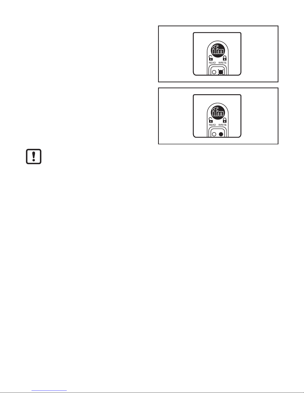
On delivery the memory plug is empty
(no parameter set saved)�
When the supply voltage is applied,
the LED WRITE flashes slowly (1 Hz)�
In this state one parameter set can be
written to the memory plug once�
Then it changes to the mode [Write
protected]�
To write a new parameter set to the device, the memory plug has to be
reset to the factory setting
(→ 6.6 Configure the memory plug via LR DEVICE)�
4 Functions and features
The memory plug saves parameter sets of IO-Link devices� It offers the following
options:
• Bi-directional backup for IO-Link V1�1 sensors�
• Bi-directional backup for IO-Link V1�0 sensors from ifm electronic�
• Preconfiguration as data carrier via PC�
4.1 Applications without PC
• Save the parameter set of a sensor once → 6.1.
• Save the parameter set of a sensor continuously → 6.2.
• Copy the parameter set of a sensor (copy to several sensors of the same type;
e�g� in series production or for fast set-up)
(→ 6.3 Copy the parameter set of a sensor)�
• Set the parameters of replacement sensors (without using further tools, without
configuration tools or menu handling) (→ 6.4)�
• Restore the parameter set of a sensor (e�g� during start-up of an installation)
(→ 6.5)�
Page 7

7
UK
4.2 Applications with IO-Link master and LR DEVICE
(software)
• Configure the memory plug via LR DEVICE (software) → 6.6.
• Write the data stored on the memory plug → 6.6.1.
• Read and edit the data stored on the memory plug → 6.6.2.
4.3 Basic operating conditions
• Negative switching sensors are not supported�
• The memory plug cannot be used with IO-Link actuators�
• IO-Link sensors with COM3 are not supported�
• The memory plug is intended for saving the data of IO-Link sensors used
without IO-Link master�
• Data in the parameter set of the sensor protected by an access code cannot be
overwritten by the memory plug�
The memory plug saves / writes data after the following operations�
• After application of the supply voltage�
• After interrupting and restoring the connection between the memory
plug and the sensor�
After saving the parameters all sensor signals are linked through without
being changed� The output function of the sensor, its quality and speed
remain unchanged� An integrated memory plug does not influence the
complete system�
Recommended operating mode:
Operation in the [Write protected] mode is recommended� This
mode ensures that a parameter set saved in the memory plug is not
unintentionally overwritten� In the [Read/Write] mode the memory plug is
not write-protected!
The manufacturer of an IO-Link sensor is responsible for providing all
parameters necessary for an exchange� The memory plug reads this
information from the sensor and saves exactly these parameters�
The memory plug cannot be used in a system with IO-Link master� The
functionality of the system cannot be guaranteed�
Page 8

8
5 Electrical connection
The memory plug is an accessory intended for connection to IO-Link
devices�
4
1
3
2
4
1
3
2
Out 2
L
+
L
BN
BU
Out 1
WH
BK
1
2
1: Sensor
2: Memory plug
Page 9

9
UK
6 Operation
6.1 Save the parameter set of a sensor once
Requirement: The memory plug is used as delivered (empty / [Write protected])�
1
► Connect the memory plug to the supply
voltage�
Ub
2
► Connect memory plug and sensor�
> The memory plug reads the parameter set
of the sensor and saves it�
Ub
P
P
Reading process
Process terminated�
Memory plug full / [Write protected]�
UB = Operating voltage; P = Parameter set
The empty memory plug can carry out this process only once� It can be reset to
the factory setting (→ 6.6.3)�
Do not install a brand new memory plug before setting the sensor
parameters�
If the memory plug is installed before parameter setting is completed, the
parameter set defined at this point will be saved and any further parameter
change of the connected sensor will be reversed with the next data
exchange�
Page 10

10
6.2 Save the parameter set of a sensor continuously
Requirement: Memory plug in the [Read/Write] mode�
To change from [Write protected] to [Read/Write] → 6.6 Memory plug parameter
setting�
1
► Connect the memory plug between the
sensor and the evaluation unit of the
installation�
Ub
P
Display when the memory plug is
empty
Display when the memory plug is full
2
The parameter set of the sensor is changed
(P → P1).
Ub
P1
3
► Disconnect the memory plug from the
sensor and connect it again�
> The memory plug reads the changed
parameter set P1 and saves it�
Ub
P1
P1
Reading process
Process terminated
Page 11

11
UK
6.3 Copy the parameter set of a sensor
Requirement: Memory plug full / in the mode [Write protected]�
1
► Connect the memory plug to the supply
voltage�
Ub
2
► Connect the memory plug with a sensor of
the same type�
> The memory plug writes its parameter set
to the sensor�
Ub
P
Writing process
Process terminated
3
► Repeat the process with sensors of the same type as often as you wish�
Ub
P
This process only works for sensors of the same type (= sensors with the same IO-Link
device ID)�
Page 12

12
6.4 Set the parameters of the replacement sensor
Requirement: Memory plug full / in the mode [Write protected] or [Read/Write]�
[Write protected] [Read/Write]
1
► Connect the memory plug to the supply
voltage�
Ub
2
► Connect the memory plug with a sensor of
the same type�
If the memory plug is used in the
[Read/Write] mode, the sensor
must have the factory setting� If in
doubt reset the sensor�
> The memory plug writes its parameter set
to the new sensor�
Ub
P
Writing process
Process
terminated
Writing process
Process
terminated
Page 13

13
UK
6.5 Restore the parameter set of a sensor
Requirement: Memory plug full / in the mode [Write protected]�
1
► Connect the memory plug between the
sensor and the evaluation unit of the
installation�
Ub
P
2
The parameter set of the sensor is changed
(P → P1).
Ub
P1
► Switch the supply voltage of the installation
off and on again�
> The memory plug writes the original
parameter set P to the sensor�
P
I
0
Writing process
Process terminated
Page 14

14
6.6 Configure the memory plug via LR DEVICE
You need an IO-Link master and the LR DEVICE software to connect the
memory plug with a PC�
► For connection and set-up, refer to the LR DEVICE operating instructions�
> The following information is displayed in the (LR DEVICE) header�
Write protection is not active:
When the memory plug is connected to a suitable sensor, the
parameters of this sensor will be written in the memory plug�
Write protection is active:
When the memory plug is connected to a suitable sensor, the data set
saved in the memory plug will be written in the sensor�
After reading of a memory plug which contains data, appears� By
clicking on the icon, the parameters of the saved device are displayed,
if this is supported by the respective device. (→ Display of the data
stored on the memory plug)
appears after clicking on � By clicking on the parameter
list of the memory plug is displayed again� The icon changes again to
�
The memory plug only provides memory space for the parameters of one
device�
6.6.1 Store data on the memory plug
► Read IO-Link parameters from a device using the LR DEVICE software or
select offline parameter setting�
► Edit parameters�
► Connect the memory plug to the IO-Link master�
► Click on [ ] to store data on the memory plug�
The write protection is activated via the system command [Write protect]�
The system command [Read/Write] deactivates the write protection�
Page 15

15
UK
6.6.2 Read and edit the data stored on the memory plug
► Connect the memory plug to the USB IO-Link master�
► Click on [ ]�
> The parameter list of the connected memory plug is loaded into the software�
► Click on [ ] if this is supported by the device�
> All stored parameters are displayed and can be edited�
► Click on [ ]�
> The parameter list of the connected memory plug is displayed�
6.6.3 Restore the factory setting of the memory plug
► Connect the memory plug to the IO-Link master�
► Click on [ ]�
> The parameter list of the connected memory plug is loaded into the software�
► Click on [ ]�
> The factory setting of the memory plug is restored�
6.7 Operation indication
No supply voltage�
Memory plug without saved parameter set in the [Write protected] mode,
factory setting�
Memory plug with saved parameter set in the [Write protected] mode�
Memory plug without saved parameter set in the [Read/Write] mode�
Page 16

16
Memory plug with saved parameter set in the [Read/Write] mode�
Memory plug reads the parameter set of the sensor�
Memory plug writes the saved parameter set in the sensor�
Memory plug in the [Read/Write] mode;
error in data processing�
Memory plug in the [Write protected] mode;
error in data processing�
The connected sensor is not of the same type�
This state remains until a sensor of the same type is connected or the
voltage supply is interrupted�
6.8 Configuration via teach button
4
1
3
2
4
1
3
2
1 2
4
1
3
2
4
1
3
2
L
+
L
BN
BU
WH
BK
3
T
1: Sensor
2: Memory plug
3: Teach button (available as accessories; order no� E30405)
T = Button
Page 17

17
UK
No sensor may be connected�
► Press the teach button for the indicated time (the end of the time span is
signalled by a change of the LED display; → following figures).
Change from [Write protected] to [Read/Write]
+Ub
0 10 <13
t [s]
A
B
A: LED display memory plug empty
B: LED display memory plug full
Change from [Read/Write] to [Write protected]
+Ub
0 10 <13
t [s]
A
B
A: LED display memory plug empty
B: LED display memory plug full
Page 18

18
Restore the factory setting of the memory plug
+Ub
0 10 15 <18
t [s]
A
A: LED display memory plug
6.9 Use the memory plug as data carrier
Memory plugs can be used as external storage medium:
► When the installation has been set up, keep units with saved parameter sets in
a safe place�
7 Technical data
Further technical data and scale drawing at www�ifm�com�
Page 19

19
UK
8 Troubleshooting
For all errors the following applies:
• The parameter set in the memory plug remains� It is not damaged by faulty
reading or writing�
• The error remains until it has been removed�
• If the memory plug detects an error, the transmission of the sensor output
(OUT1, pin 4) to the higher-level system is stopped�
Error in data processing
Cause of the fault Corrective measures
Sensor cable removed during transmission� ► Connect the sensor cable to the memory
plug again�
Unknown sensor connected, e�g�
• IO-Link 1�0 sensor of another
manufacturer�
• Sensor not equipped with IO-Link �
► Connect an IO-Link 1�0 sensor from ifm
electronic�
► Connect an IO-Link 1�1 sensor�
The sensor does not support any saving
of data�
► Connect a sensor supporting IO-Link
and saving of data (→ data sheet of the
sensor)�
Sensor locked, writing impossible� ► Unlock the sensor or connect an
unlocked sensor�
The identification of the connected sensor does not correspond to the parameter set in the
memory plug�
Cause of the fault Corrective measures
The connected sensor is neither of the
same type nor compatible�
► Connect a sensor of the same type (=
sensor with the same IO-Link device ID) or
another compatible sensor�
More information at www�ifm�com
 Loading...