

Page 1
Programming instructions
IO-Link Display 1,44”
E30391
Page 2

Content
1. Installation and electrical connection .............................................. 3
2. Set-up............................................................................................. 3
3. Parameter setting (acyclic communication) .................................... 5
3.1.
3.2.
3.3.
3.4.
3.5.
3.6.
3.7.
3.8.
Parameter setting with LINERECORDER DEVICE ............ 6
Process value display ........................................................ 7
Text content for info pages ................................................ 7
Background colour of the info pages .................................. 9
Free text instead of process values ................................... 9
Predefined text instead of process values........................ 11
Display configuration ........................................................ 13
QR code ........................................................................... 13
4. IO-Link process data (cyclic communication) ............................... 14
4.1.
Output data ...................................................................... 14
4.2.
4.3.
4.3.1.
4.3.2.
4.3.3.
4.3.4.
Input data ......................................................................... 16
Examples ......................................................................... 17
Example 1: display one process value ............................. 17
Example 2: display two process values ........................... 18
Example 3: display text instead of process values ........... 19
Example 4: display info pages ......................................... 19
4.3.5. Example 5: Display QR-Code ............................................. 20
5. Technical data .............................................................................. 20
5.1.
Identification parameters .................................................. 20
2
Page 3
Technical data, approvals, accessories and further
information at www.ifm.com
1. Installation and electrical connection
For installation and electrical connection please read see the
operating instructions → www.ifm.com.
2. Set-up
When the IO-Link Display is connected to an IO-Link master the
IO-Link port has to be configured.
In this example the IO-Link master AL1000 from ifm electronic
is used with the Siemens software Step 7.
The IO-Link Display has an interface with 1-byte input (→ 4.2 Input
data) and 14-byte output (→ 4.1 Output data).
3
Page 4
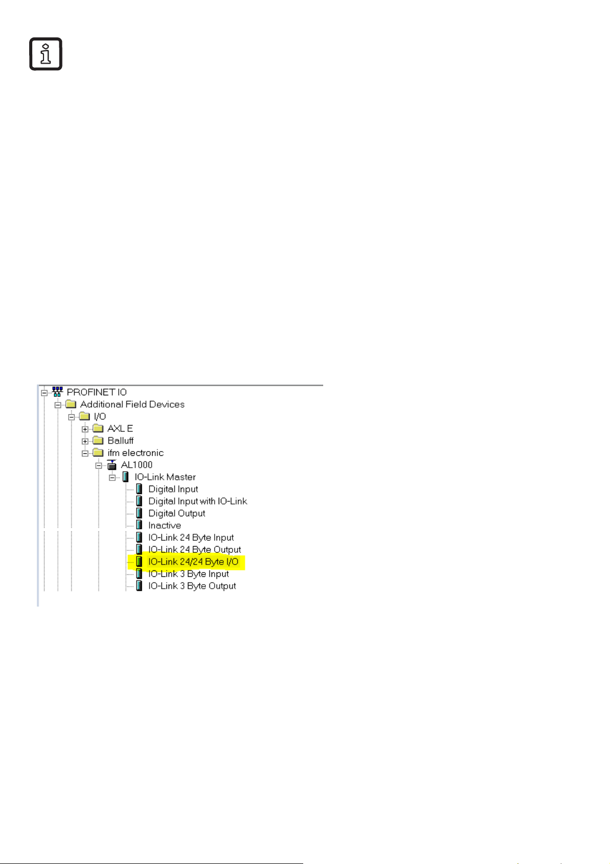
If there is no explicit module on the master used it is possible to use
an existing module with a wider interface.
1.
Drag, for example, a 24/24-byte I/O module to the master port
to which the IO-Link Display is to be connected.
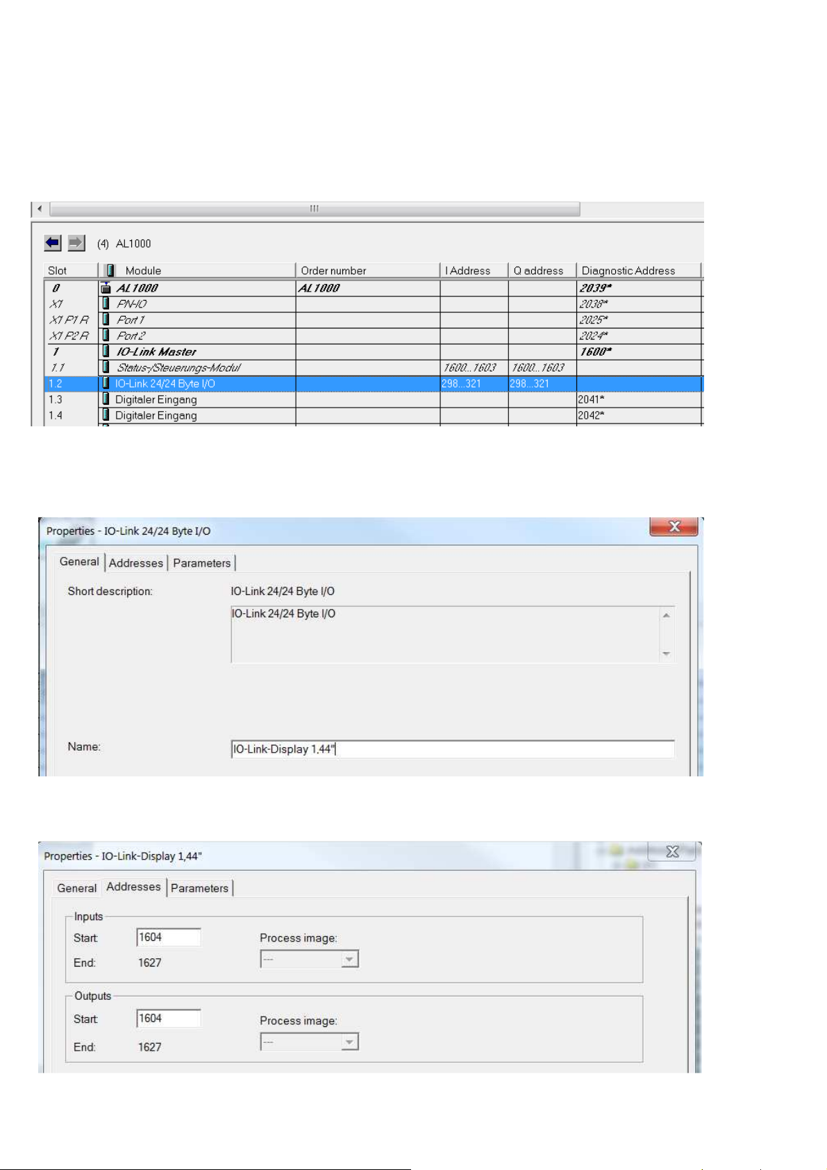
2.
Double click on the module:
3.
Enter name and comment as an option:
4.
Enter addresses for input and output ranges:
4
Page 5
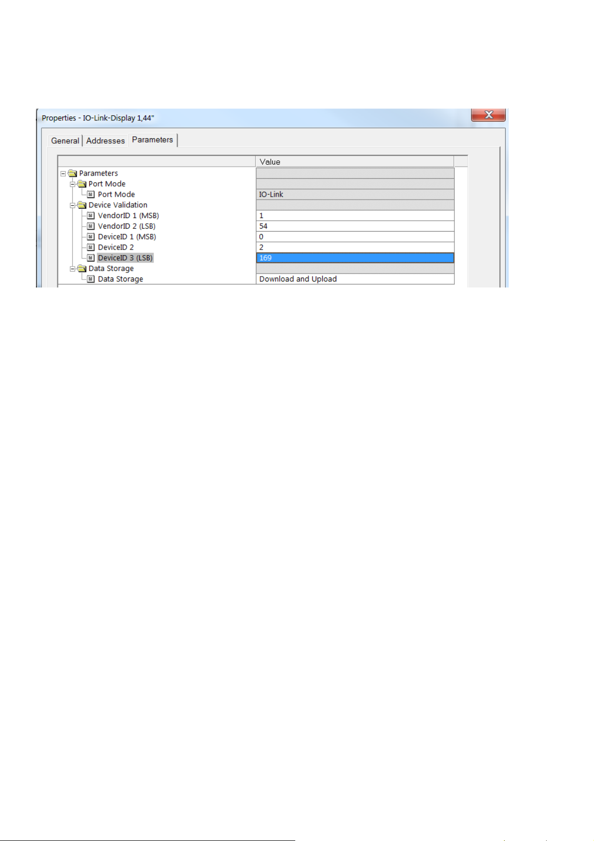
5.
Enter vendor ID and device ID to ensure that only an IO-Link
Display 1,44” can be operated at that port.
6.
Set the data storage according to the application's requirements:
7.
Write the configuration to the controller or PLC.
8.
Connect the IO-Link Display to the master using a 3-wire cable.
3. Parameter setting (acyclic communication)
Settings can be made and predefined text can be entered by
means of the IO-Link parameter setting tool or a PLC by writing
the corresponding parameters.
The LINERECORDER DEVICE can for example be used as
IODD-based parameter setting tool (→ 3.1).
It is possible to configure the following properties:
•
Process value display (unit, description text, decimal places) →
3.2
•
Text content for info pages → 3.3
•
Background colour of the info page → 3.4
•
Text instead of process values → 3.5; → 0
•
Display layout → 3.7
•
Content of a QR code → 3.8
The process values, colours and layout switching are controlled
via the cyclic communication of the controlling PLC. (→ 4 )
5
Page 6
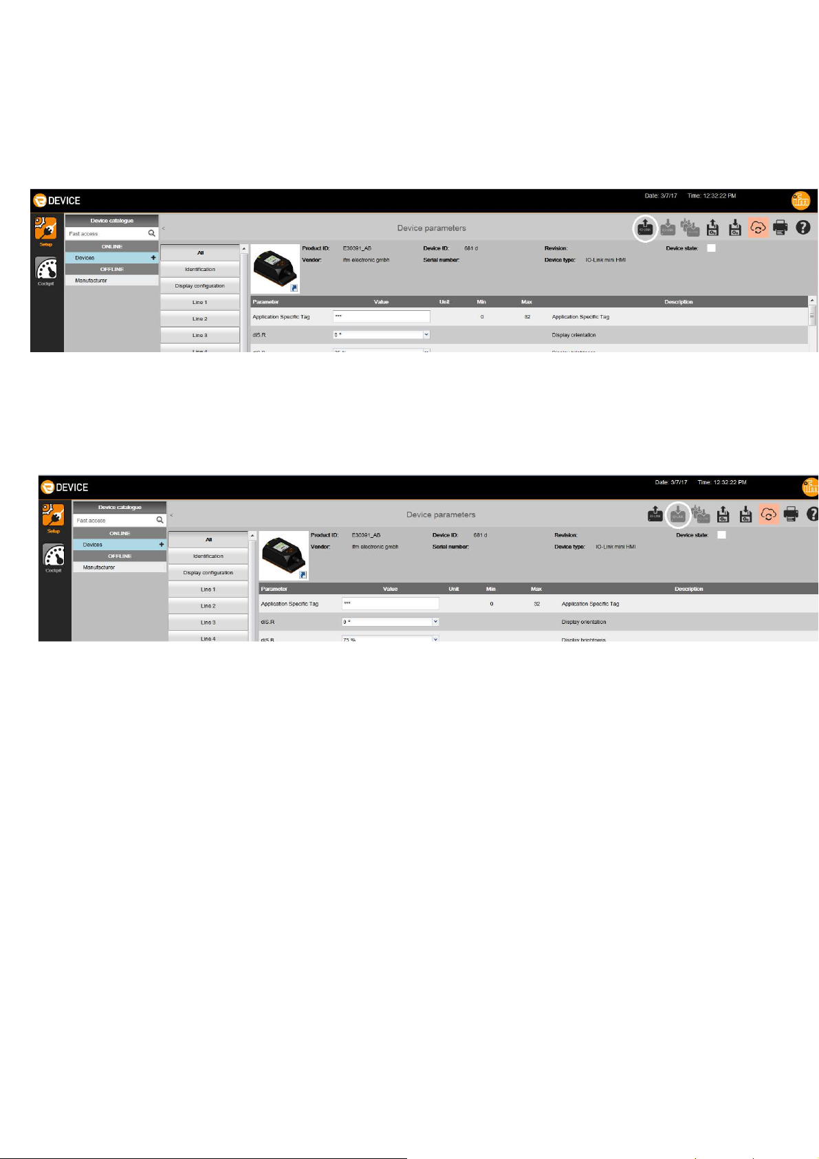
3.1.
Parameter setting with LINERECORDER DEVICE
► Connect the IO-Link Display via the USB interface E30390.
► Start the LINERECORDER DEVICE.
► Read parameters from the IO-Link Display:
► Change parameters.
► Write parameters to the IO-Link Display:
> The IO-Link Display can now be connected to the IO-Link master.
6
Page 7

3.2.
Process value display
Name Index /
subinde
Unit 1 80/0
Unit 2 81/0
Unit 3 82/0
Unit 4 83/0
Description 1 90/0
Description 2 91/0
Description 3 92/0
Description 4 93/0
Decimal place 1 100/0
Decimal place 2 101/0
Decimal place 3 102/0
Decimal place 4 103/0
x
Type /
length
String/8
String/16
UINT8/1
Content
Units of the process
values
Description text of
the process values
Number of decimal places of
the process values:
0 = no decimal place
1 = 1 decimal place
2 = 2 decimal places
3.3.
Text content for info pages
Up to 16 characters per line can be used.
Name Index /
subind
Info page 1, line 1 120/0
Info page 1, line 2 121/0
Info page 1, line 3 122/0
Info page 1, line 4 123/0
Info page 1, line 5 124/0
Info page 2, line 1 125/0
Info page 2, line 2 126/0
ex
Type /
length
String/16
3 = 3 decimal places
Content
Text content of page 1
Info page 2, line 3 127/0
String/16
Text content of page 2
Info page 2, line 4 128/0
Info page 2, line 5 129/0
7
Page 8

Name Index /
subindex
Info page 3, line 1 130/0
Info page 3, line 2 131/0
Info page 3, line 3 132/0
Info page 3, line 4 133/0
Info page 3, line 5 134/0
Type /
length
String/16
Content
Text content of page 3
Info page 4, line 1 135/0
Info page 4, line 2 136/0
Info page 4, line 3 137/0
Info page 4, line 4 138/0
Info page 4, line 5 139/0
Info page 5, line 1 12100/0
Info page 5, line 2 12101/0
Info page 5, line 3 12102/0
Info page 5, line 4 12103/0
Info page 5, line 5 12104/0
Info page 6, line 1 12105/0
Info page 6, line 2 12106/0
Info page 6, line 3 12107/0
String/16
String/16
String/16
Text content of page 4
Text content of page 5
Text content of page 6
Info page 6, line 4 12108/0
Info page 6, line 5 12109/0
Info page 7, line 1 12110/0
Info page 7, line 2 12111/0
Info page 7, line 3 12112/0
Info page 7, line 4 12113/0
Info page 7, line 5 12114/0
Info page 8, line 1 12115/0
Info page 8, line 2 12116/0
Info page 8, line 3 12117/0
Info page 8, line 4 12118/0
Info page 8, line 5 12119/0
String/16
String/16
Text content of page 7
Text content of page 8
8
Page 9

Name Index /
subind
Info page 9, line 1 12120/0
Info page 9, line 2 12121/0
Info page 9, line 3 12122/0
Info page 9, line 4 12123/0
Info page 9, line 5 12124/0
Info page 10, line 1 12125/0
Info page 10, line 2 12126/0
Info page 10, line 3 12127/0
Info page 10, line 4 12128/0
Info page 10, line 5 12129/0
Type
/
String/16
String/16
Content
Text content of page 9
Text content of page 10
3.4.
Background colour of the info pages
Name
Background colour info page
Background colour info page
Background colour info page
Background colour info page
Background colour info page
Background colour info page
Background colour info page
Background colour info page
Background colour info page
Background colour info page
Index /
subind
ex
140/0
141/0
142/0
143/0
144/0
145/0
146/0
147/0
148/0
149/0
Type /
length
INT8/1
Content
Page colour:
0 = black-white
1 = red
2 = green
3 = yellow
3.5.
Free text instead of process values
Text defined by the user which can be displayed instead of process
values.
9
Page 10

Name Index /
subindex
Text 1 161/0
Text 2 162/0
Text 3 163/0
Text 4 164/0
Text 5 165/0
Text 6 166/0
Text 7 167/0
Text 8 168/0
Text 9 169/0
Text 10 170/0
Text 11 171/0
Text 12 172/0
Type /
length
Content
Text 13 173/0
Text 14 174/0
Text 15 175/0
Text 16 176/0
Text 17 177/0
Text 18 178/0
Text 19 179/0
Text 20 180/0
Text 21 181/0
Text 22 182/0
Text 23 183/0
Text 24 184/0
Text 25 185/0
Text 26 186/0
String/16
Text which can be
freely defined.
Maximum length: 16
bytes
Text 27 187/0
Text 28 188/0
Text 29 189/0
Text 30 190/0
Text 31 191/0
Text 32 192/0
10
Page 11

3.6.
Predefined text instead of process values
Text defined in the device which can be used instead of process
values.
Index /
subindex
1000/0 String/16 C
1001/0 String/16 °C
1002/0 String/16 °F
1004/0 String/16 rad
1005/0 String/16 °
1010/0 String/16 m
1012/0 String/16 cm
1013/0 String/16 mm
Type /
length
Text
1019/0 String/16 in
1034/0 String/16 m³
1038/0 String/16 l
1040/0 String/16 ml
1048/0 String/16 gal
1053/0 String/16 ft³ std.
1054/0 String/16 s
1056/0 String/16 ms
1058/0 String/16 min
1061/0 String/16 m/s
1062/0 String/16 mm/s
1067/0 String/16 ft/s
1076/0 String/16 m/s²
1077/0 String/16 Hz
1081/0 String/16 kHz
1082/0 String/16 1/s
1083/0 String/16 1/min
1085/0 String/16 rpm
1130/0 String/16 Pa
1132/0 String/16 MPa
11
Page 12

Index /
subindex
Type /
length
Text
1133/0 String/16 kPa
1136/0 String/16 hPa
1137/0 String/16 bar
1138/0 String/16 mbar
1141/0 String/16 psi
1146/0 String/16 inH2O
1149/0 String/16 mmH2O
1155/0 String/16 inHg
1157/0 String/16 mmHg
1211/0 String/16 mA
1212/0 String/16 µA
1240/0 String/16 V
1243/0 String/16 mV
1342/0 String/16 %
1348/0 String/16 m³/min
1349/0 String/16 m³/h
1352/0 String/16 l/min.
1353/0 String/16 l/h
1357/0 String/16 ft³/min
1358/0 String/16 ft³/h
1360/0 String/16 ft³/min std.
1361/0 String/16 ft³/h std.
1363/0 String/16 gal/min
1364/0 String/16 gal/h
1563/0 String/16 ml/min
1573/0 String/16 Nm³
1574/0 String/16 Nl
1589/0 String/16 Nm³/min
1590/0 String/16 Nm³/h
1593/0 String/16 Nl/min
12
Page 13

3.7.
Display configuration
Definition of rotation, brightness and colour scheme of the display.
Name
Index /
subindex
diS.R 801/0
diS.B 802/0
diS.S 803/0 Colour scheme of the
3.8.
QR code
Type /
length
UINT8/1
Content
Rotation of the display
Setting values: 0°, 90°, 180°, 270°
Brightness of the display:
0 %, 25 %, 50 %, 75 %, 100 %
display: 0 = black
background 1 = white
To display the content defined in this index as QR code on the
screen set the layout type of the display to [QR-Code] → 4.1
Name
Index /
subindex
QR code 830/0 String/122 URL or short free text
Type /
length
Content
13
Page 14

PLC
9846432
1
8
0
PDV
PDV
PDV
PDV4
Color1 Color2 Color3 Color4
LED
0.0 2.0 4.0 6.0 8.0 9.0 10.0
11.0
12.0
Addressing PLC
4. IO-Link process data (cyclic communication)
4.1.
Output data
The connected PLC transmits process values in the output data
stream and controls the display of the process values.
It is defined in the layout byte which layout is to be displayed, e.g. 1
large process value or an info page.
INT16 INT16 INT16 INT16
13.0
Name Byte
offset
Type /
length
INT8 INT8 INT8 INT8 INT8 INT8
Note /
content
PDV1: value line 1 0.0
PDV2: value line 2 2.0
PDV3: value line 3 4.0
PDV4: value line 4 6.0
INT16/2
Process value x or text
saved instead of the process
value (→ 3.5; → 3.5).
14
Page 15

Name Byte
offset
Color1: Display
8.0
line 1
Color2: Display
9.0
line 2
Color3: Display
10.0
line 3
Color1: Display
11.0
line 4
Type /
length
INT8/1
Note /
content
Colour and flashing (frequency 2 Hz)
Colour of the static
process value:
0 = black-white
1 = red
2 = green
3 = yellow
Colour of the static display text:
80 = text black and white
81 = text red
82 = text green
83 = text
yellow
Colour of the flashing
process value:
40 = black-white
LEDs 12.0 Bool
/ 1
12.1 Bool
/ 1
41 = red
42 = green
43 = yellow
Colour of the flashing
display text:
120 = text black and white
121 = text red
122 = text green
123 = text
yellow
0 = LED I off
1 = LED I yellow
reserved
12.2 Bool
/ 1
12.3...12.7
0 = LED II off
1 = LED II yellow
reserved
15
Page 16

6 5 4 3 2 1 0
Name Byte
offset
Type /
length
Display layout 13.0 INT8/1
Note /
content
0 = Start screen
1 = layout 1 for one process value
2 = layout 2 for two process values
3 = layout 3 for three process values
4 = layout 4 for four process values
11 = display info page 1
12 = Display info page 2
13 = Display info page 3
14 = Display info page 4
15 = Display info page 5
16 = Display info page 6
17 = Display info page 7
18 = Display info page 8
19 = Display info page 9
20 = Display info page 10
4.2.
21 = display of the QR code
Input data
7
Bit
PDout inv
Function
If a key is pressed, the corresponding flag is active.
During the runtime the following input data is available as INT8
value:
Content inv
Reserved
ESC
Enter
Up
Down
Address / bit Function Description
0 Down Down key pressed
1 Up Up key pressed
2 Enter Enter key pressed
3 ESC Up and down keys pressed
16
Page 17

Address / bit Function Description
4 --- Reserved
5 --- Reserved
6 Content inv The device found out that at least
one of the received output data
(→ 9.1 Output data) is
inconsistent.
7 PDout inv
4.3.
Examples
The device confirms that the received
output data (→ 9.1 Output data) had
already been marked as invalid by the
transmitter.
4.3.1. Example 1: display one process value
1.
Define unit, description text and number of decimal places
(index 80, 90 and 100 → 3.2).
2.
In the output data stream, set the layout to 1 (byte 13 → 4.1).
3.
As an option, define a text colour (byte 8 → 4.1).
4.
Write the display value as Integer16, starting at byte 0 in the
output data (→ 4.1).
17
Page 18

4.3.2. Example 2: display two process values
1.
Define unit, description text and number of decimal places
(index 80, 90 and 100 → 3.2)
2.
In the output data stream, set the layout to 2 (byte 13 → 4.1).
3.
As an option define the text colours (byte 8 → 4.1).
4.
Write both display values as Integer16, starting at byte 0 in the
output data (→ 4.1).
18
Page 19

4.3.3. Example 3: display text instead of process values
1.
Define text for a certain text ID (index 160 to 174 → 3.5; 0).
2.
Use this text ID for the requested process value by setting text
red or text black and white. At the same time this defines a
text colour (bytes 8 to 11 → 4.1).
4.3.4. Example 4: display info pages
1.
Define text of info page 1. Up to 16 characters per line can be
used (index 120 to 124 → 3.3).
2.
As an option select a background colour (index 140 → 3.4).
3.
During the runtime set the layout to 11 to display info page 1
(byte 13 → 4.1).
19
Page 20

4.3.5. Example 5: Display QR-Code
1.
Define the QR-Code’s text (Index 830→ 3.8).
2.
In order to display the QR-Code on the display
set the layout to 21 during run time (Byte 13 → 4.1).
5. Technical data
Technical data and scale drawing at www.ifm.com.
5.1.
These parameters contain the identification data of the IO-Link device.
Name Index /
Vendor name 16/0
Vendor text 17/0 String/11 www.ifm.com
Product name 18/0 String [9 E30391_AB
Product ID 19/0 String/6 E30391
Product text 20/0 String/15 IO-Link Display
Identification parameters
subind
Type /
length
String/19
Content
ifm electronic gmbh
Serial number 21/0 String/12 Unique device identification
Hardware version 22/0 String/2 Hardware version
Software Version 23/0 String/5 Software Version
User-specific
marking
24/0 String/32 Free text of measuring
point or device
20
 Loading...