

Page 1
UK
Installation instructions
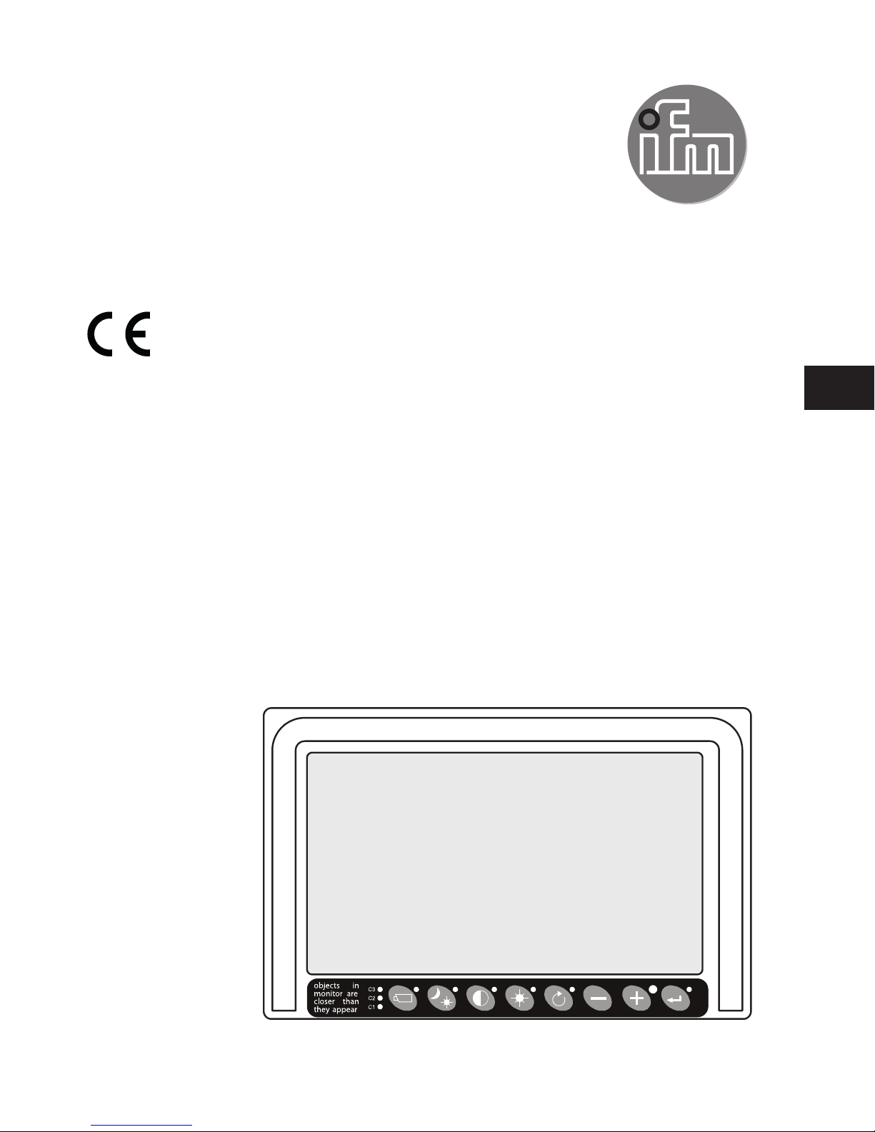
Monitor for analogue cameras
E2M231
E2M232
80269533 / 00 08 / 2017
Page 2

2
Contents
1 Preliminary note ������������������������������������������������������������������������������������� 4
1�1 Symbols used ���������������������������������������������������������������������������������� 4
1�2 Warnings used ��������������������������������������������������������������������������������� 4
2 Safety instructions ��������������������������������������������������������������������������������� 5
3 Functions and features �������������������������������������������������������������������������� 5
4 Items supplied����������������������������������������������������������������������������������������6
5 Installation����������������������������������������������������������������������������������������������7
5�1 Mounting accessories ���������������������������������������������������������������������� 7
5�2 Locator for mounting accessories ���������������������������������������������������� 8
5�3 Rotate cable connection ������������������������������������������������������������������ 9
6 Electrical connection ���������������������������������������������������������������������������� 11
6�1 Connection accessories ���������������������������������������������������������������� 11
6�2 Wiring��������������������������������������������������������������������������������������������� 11
6�3 Connection and laying of cables ���������������������������������������������������� 12
6�4 Operating voltage and fuses ���������������������������������������������������������� 12
6�4�1 Vehicles with separate ground ����������������������������������������������13
6�4�2 Vehicles with chassis ground �����������������������������������������������13
6�5 Analogue video inputs ������������������������������������������������������������������� 14
6�6 Activate cameras ��������������������������������������������������������������������������� 14
6�7 Set up the camera monitor system ������������������������������������������������ 15
6�8 Application examples ��������������������������������������������������������������������� 16
6�8�1 Connect device with 1 camera ��������������������������������������������� 16
6�8�2 Connect device with 2 cameras �������������������������������������������� 16
6�8�3 Connect device with 3 cameras �������������������������������������������� 17
6�8�4 Connect device with 4 cameras �������������������������������������������� 17
7 Maintenance, repair and disposal �������������������������������������������������������� 18
Page 3

3
UK
7�1 Cleaning ��������������������������������������������������������������������������������������� 18
7�2 Repair �������������������������������������������������������������������������������������������� 18
7�3 Disposal ����������������������������������������������������������������������������������������� 18
8 Approvals/standards ���������������������������������������������������������������������������� 19
Licences and trademarks
All trademarks and company names used are subject to the copyright of
the respective companies�
Page 4

4
1 Preliminary note
This document is intended for specialists� These specialists are people
who are qualified by their appropriate training and their experience to see
risks and to avoid possible hazards that may be caused during operation
or maintenance of the device� The document contains information about
the correct handling of the device�
Read this document before use to familiarise yourself with operating
conditions, installation and operation� Keep this document during the
entire duration of use of the device�
1.1 Symbols used
► Instructions
> Reaction, result
[…] Designation of keys, buttons or indications
→ Cross-reference
Important note
Non-compliance may result in malfunction or interference�
Information
Supplementary note
1.2 Warnings used
NOTE
Warning of damage to property�
Page 5

5
UK
2 Safety instructions
These instructions are part of the device� They contain texts and figures
concerning the correct handling of the device and must be read before
installation or use�
Note the safety instructions� Use the device in accordance with its
designated use�
The installation and connection must comply with the applicable national
and international standards� Responsibility lies with the person installing
the device�
Only the signals indicated in the technical data or on the device label may
be supplied to the connections or wires�
The device may only be opened by the manufacturer or by a person
authorised by the manufacturer�
3 Functions and features
The E2M23x monitor processes input signals from analogue cameras
and displays them� The parameters of the device are set via integrated
buttons� The device is available in 2 versions:
• with 1 analogue video input (E2M231)
• with 2 analogue video inputs (E2M232)
The following cameras from ifm electronic are compatible with the device:
• O2M2xx
• O3M2xx
Because of the requirements for electromagnetic interference emissions,
the device is intended for use in industrial environments� The device is
not designed for use in domestic areas�
Page 6
6
The device may only be used under the operating conditions
specified in the data sheet�
NOTE
Touching the display may result in permanent pixel errors�
► Do not touch the screen�
4 Items supplied
• E2M23x monitor
• Connection cable for power supply
• Only E2M231: connection cable for 1 analogue video input and
controller
• Only E2M232: connection cable for 2 analogue video inputs and
controller
• Installation instructions
► In the event of incomplete or damaged items supplied please contact ifm
electronic�
The device is supplied without installation / connection
accessories�
► Only use accessories from ifm electronic gmbh�
Available accessories:
www�ifm�com
The optimum function is not ensured when using components
from other manufacturers�
Page 7

7
UK
5 Installation
5.1 Mounting accessories
The device is supplied without mounting accessories�
The hole dimensions of the device are not compatible with the
standard RAM® mounting plate� Install the device using one of the
following accessories:
• E2M236 - mounting arm monitor 90 mm
• E2M237 - mounting arm monitor 144 mm
• E2M238 - mounting plate monitor
• E2M239 - monitor bracket
Information about the available accessories:
www�ifm�com
Page 8

8
5.2 Locator for mounting accessories
The back of the device has been prepared for fixing the mounting
accessories� The 11 M5 tapped holes have a thread length of 8 mm�
188
120
40,5
30 3030
81
Locator for mounting accessories (back of the unit)
Screw the mounting accessories to the device applying 2 Nm�
Page 9

9
UK
5.3 Rotate cable connection
The cable connection of the device can be rotated by 180 degrees� This
allows that the cables from the device can be laid from the top or the
bottom�
NOTE
The protection rating indicated in the data sheet is ensured if the
device continues to be ingress-resistant after the cable connection has
been rotated�
► The cable connection must be connected by a qualified electrician�
► Disconnect power before connecting the device�
1
2
3
5
1� Remove rubber stopper of the cable
connection (1)�
2� Loosen the socket head screws of the cable
connection (2)�
3� Remove cable connection from the device (3)�
4
5
4� Loosen JST connector and carefully rotate by
180 degrees (4)�
5
5� Insert JST connector into the cable connection
(5)�
Page 10

10
1
2
3
5
8
7
6
6� Place the cable connection on the device
rotated by 180 degrees (6)�
7� Tighten the cable connection with socket head
screws applying 0�35 Nm (7)�
8� Verify correct and tight position of the cable
connection�
9� Insert the rubber stopper into the cable
connection (8)�
Page 11

11
UK
6 Electrical connection
NOTE
The device must be connected by a qualified electrician� Observe the
electrical data in the data sheet�
Device of protection class III (PC III)�
The electrical supply must only be made via PELV circuits�
For cable lengths > 30 m use an additional protection against surge
voltages to IEC 6100-4-5�
Disconnect power before connecting the device�
Cover unused connectors with protective caps�
6.1 Connection accessories
Information about the available accessories:
www�ifm�com
6.2 Wiring
1
2
E2M231
(1) Power supply
7 cables, open ends
red
white
blue
brown
white/
yellow
grey
yellow
U+ (18���30 V DC)
GND
Activate camera 1
Activate camera 2
Activate camera 3
Activate camera 4/
tachometer
Parking brake
Page 12

12
1
2
E2M232
(2) Analogue video input
M16 socket, 4 poles
2
1
3
4
1
2
3
4
Coax cable core
(video signal)
Coax screen
(video GND)
U+ (12 V DC)
GND
6.3 Connection and laying of cables
► Use screened cables from ifm:
www�ifm�com
E2M203: M16 connection cable, gold-plated contacts, 5 m long
E2M204: M16 connection cable, gold-plated contacts, 11 m long
E2M205: M16 connection cable, gold-plated contacts, 16 m long
E2M206: M16 connection cable, gold-plated contacts, 21 m long
► Use screened connector housings�
► Do not lay the cables in parallel to live cables�
► Lay supply and signal cables away from the cameras using the
shortest possible route�
6.4 Operating voltage and fuses
NOTE
Not using a common ground can damage the device and certain
cameras� If an O3M2xx is used as camera:
► Connect GND connections of O3M2xx and E2M23x�
Page 13

13
UK
Protect the supply voltage (max� 5 A) to protect the device�
6.4.1 Vehicles with separate ground
For vehicles with separate power wiring (e�g� fork lift trucks) connect the
operating voltage as follows:
► Connect the red wire (U+) of the operating voltage cable
(→ 6.2 Wiring) with + (plus) of the vehicle (18-30 VDC, 5 A fuse)�
► Connect the white wire (GND) of the operating voltage cable
(→ 6.2 Wiring) with - (minus) of the vehicle�
► Connect the shield of the operating voltage cable (→ 6.2 Wiring) with
the vehicle chassis�
In no case must the shield be connected with - (minus) of the
vehicle�
6.4.2 Vehicles with chassis ground
For vehicles without separate ground or if - (minus) of the vehicle is
connected with the chassis, connect the operating voltage as follows:
► Connect the red wire (U+) of the cable operating voltage
(→ 6.2 Wiring) with + (plus) of the vehicle (18-30 VDC, 5 A fuse)�
► Connect the white wire (GND) and the shield of the cable operating
voltage (→ 6.2 Wiring) with - (minus) of the vehicle�
Page 14

14
6.5 Analogue video inputs
NOTE
Disconnect the power supply before the camera is connected�
The analogue video inputs are not short-circuit proof�
Observe the bending radius of the cable of >= 50 mm�
Cover unused connectors with protective caps�
The following cameras from ifm electronic are compatible with the device:
• O2M2xx
• O3M2xx
Using the E2M235 accessory (video switcher) the number of cameras to
be connected can be increased:
E2M231 E2M232
Without accessories 1 camera 2 cameras
With E2M235 accessory (video switcher) 3 cameras 4 cameras
6.6 Activate cameras
The device displays the camera image by applying voltage to the
following cables:
Camera Cable Voltage
1 blue 7���30 V DC
2 brown 7���30 V DC
3 white/yellow 7���30 V DC
4 grey 7���30 V DC
Page 15

15
UK
If several voltages are applied simultaneously, the camera with
the highest number takes priority and its images are displayed�
Example: 7���30 V DC are applied to cameras 1 and 2� The
image from camera 2 is displayed�
A camera image is no longer displayed if the voltage drops to
"< 5 V DC"�
6.7 Set up the camera monitor system
The German Road Traffic Licensing Regulations (StVZO) stipulate
equipment to observe the part of the road around the vehicle which is
not directly visible� Such equipment may be for example camera monitor
systems�
To use the device as a camera monitor system the tachometer and the
parking brake have to be connected with the device:
Vehicle Cable Voltage
Tachometer grey 7���30 V DC
Parking brake yellow 7���30 V DC
Install and align the camera according to StVZO�
To use the camera monitor system set the „AUX wire function“ in
the „Frontcam“ menu to „TCH“ (→ Operating instructions).
Page 16

6.8 Application examples
6.8.1 Connect device with 1 camera
1 32
Connection of 1 O2M200 analogue camera with an E2M231 monitor
1� E3M231 monitor
2� E2M203 connection cable, 5 m
3� O2M200 analogue camera
6.8.2 Connect device with 2 cameras
1 2 43
Connection of 2 O2M200 analogue cameras with an E2M231 monitor
1� E3M231 monitor
2� E2M235 video switcher, 3 ports
3� E2M203 connection cable, 5 m
4� O2M200 analogue camera
Page 17

17
UK
6.8.3 Connect device with 3 cameras
1 2 3 4
Connection of 3 O2M200 analogue cameras with an E2M231 monitor
1� E3M231 monitor
2� E2M235 video switcher, 3 ports
3� E2M203 connection cable, 5 m
4� O2M200 analogue camera
6.8.4 Connect device with 4 cameras
1 2 43
Connection of 4 O2M200 analogue cameras with an E2M232 monitor
1� E3M232 monitor
2� E2M235 video switcher, 3 ports
3� E2M203 connection cable, 5 m
4� O2M200 analogue camera
Page 18

18
7 Maintenance, repair and disposal
7.1 Cleaning
Unsuitable cleaning agents and chemicals can damage the
display surface�
The following agents are not suited for cleaning the display:
• chemicals dissolving plastics such as methylated spirit,
benzine, thinner, alcohol, acetone or ammonia
• paper towels, crepe paper etc�
• abrasive cleaners etc�
• polish or wax
► Disconnect the device�
► Clean the device from dirt using a soft, chemically untreated and dry cloth�
► In case of heavy dirt, use a high-quality foam cleaning agent and a damp
cloth�
Micro-fibre cloths without chemical additives are recommended�
7.2 Repair
► The device must only be repaired by the manufacturer�
Observe the safety instructions (→ 2 Safety instructions)�
7.3 Disposal
► Dispose of the device in accordance with the national environmental
regulations�
Page 19

19
UK
8 Approvals/standards
The CE declaration of conformity and approvals can be found at:
www�ifm�com
 Loading...