

Page 1
Operating Instruction
Touch Panel PC
E2D400
706018 / 01 06 / 2014
UK
Page 2
2
1 Functions and features
The Touch Panel PC is a control processor with a touch screen and can be flexibly mounted. The device ensures configuration and monitoring of the following
systems:
● object recognition sensors
● 3D vision sensors
● multicode readers
● RFID readers
2 Installation
2.1 Wall mounting
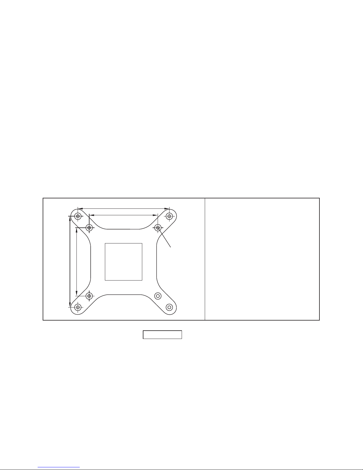
For mounting on a wall fixture the back of the Touch Panel PC is equipped with
threaded holes in accordance with the VESA 75/100 standard:
75
75
100
100
M4
Distance between the internal threaded
holes:75 x 75mm
Distance between the external threaded
holes:100 x 100mm
Mounting screws: 4 x M4, max. thread
length 4 mm
For a suitable wall fixture see:
www.ifm.com
→ Data sheet search → E2D401
Page 3
UK
3
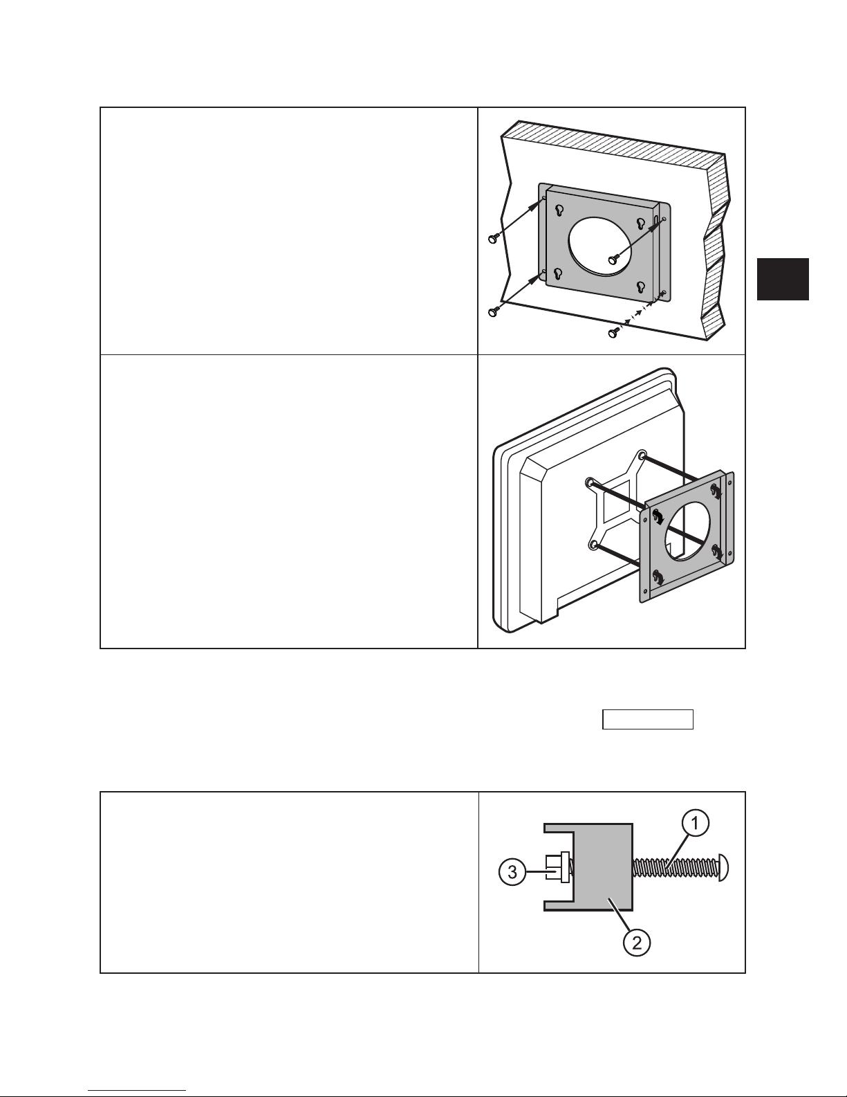
2.1.1 Mounting using the wall xture E2D401
► Mount the wall fixture on a free, flat sur-
face using four screws.
Make sure that the fixture is safely screwed
and the wall can carry the weight of the
Touch Panel PC.
The mounting holes of the wall fixture meet
the VESA 100 standard.
► Screw the four supplied M4 screws in
the external threaded holes of the Touch
Panel PC and tighten them.
► Insert the screw heads in the mounting
holes of the wall fixture and pull the Touch
Panel PC downwards carefully.
Check that all four screws are safely located
in the mounting holes.
2.2 Control panel mounting
The mounting set E2D402 is suitable for control panel mounting:
www.ifm.com
→
Data sheet search → E2D402
Panel mounting using this mounting set is described in the following section.
► Screw the screws (1) of the mounting set
into the six brackets (2).
► Position and securely fasten the plastic
caps (3).
Page 4

4
To fix the Touch Panel PC in a control panel,
a rectangular cutout 224 mm x 282 mm is
required.
Max. material thickness of the panel: 5 mm
282
224
► Insert the Touch Panel PC into the cutout.
Note that the protection rating of IP64 of the
front is only guaranteed with suitable sealing.
There are matching slots at the side of the
Touch Panel PC for fixing the brackets.
► Insert the brackets in the fixing slots.
► Fasten the screws of the brackets to fix
the mounting frame.
Page 5

UK
5
► Insert the mounting frame with the Touch
Panel PC in the control cabinet and fasten
it.
3 Electrical connection
1: audio output, 3.5 mm jack socket
2: reset button
3: USB 2.0 interfaces
4: RJ45 Ethernet interfaces
5: AT/ATX switch
6: VGA connector
7: COM3 interface (RS232/422/485)
8: COM1 interface (RS232)
9: voltage supply 9...28 V DC
coaxial power connector, lockable
10: mains switch
The Touch Panel PC is supplied via an external power supply (supplied with the
device).
► Connect the DC power supply plug with the supply socket (9) of the Touch
Panel PC.
► Connect the sensor with the Touch Panel PC via one of the RJ45 Ethernet
interfaces (4).
You can find matching connection cables at:
www.ifm.com
.
In addition to the Ethernet interface the Touch Panel PC also has four USB 2.0 and
two serial interfaces.
Page 6

6
4 Set-up
The Windows® 7 operating system and the user software for the sensors are
already preinstalled on the Touch Panel PC.
► Press the mains switch (10) to start.
When the PC is completely started up, the desktop environment is displayed.
4.1 Starting of the operating software of the connector sensor.
On the desktop there are shortcuts to the operating programs of the supported
sensors.
► Double-click on the program link to the requested operating program.
> The operating program will start.
For more detailed information about the network configuration and parameter setting we refer you to the programming manual of the sensor.
Page 7

UK
7
 Loading...