

IFM Electronic DTE800, DTE900 Operating Instructions Manual
Operating Instructions
RFID-UHF-Reader
DTE800
DTE900
704968 / 00 02 / 2011
UK

2
Contents
1 Foreword and general information � � � � � � � � � � � � � � � � � � � � � � � � � � � � � � � � � � � � � � � � � � � � � � � � � � � � � �3
1�1 Copyright notice � � � � � � � � � � � � � � � � � � � � � � � � � � � � � � � � � � � � � � � � � � � � � � � � � � � � � � � � � � � � � � � �3
1�2 Scope � � � � � � � � � � � � � � � � � � � � � � � � � � � � � � � � � � � � � � � � � � � � � � � � � � � � � � � � � � � � � � � � � � � � � � � �3
1�3 General information � � � � � � � � � � � � � � � � � � � � � � � � � � � � � � � � � � � � � � � � � � � � � � � � � � � � � � � � � � � � �3
1�4 Warranty � � � � � � � � � � � � � � � � � � � � � � � � � � � � � � � � � � � � � � � � � � � � � � � � � � � � � � � � � � � � � � � � � � � � � � 3
1�5 Disposal instruction � � � � � � � � � � � � � � � � � � � � � � � � � � � � � � � � � � � � � � � � � � � � � � � � � � � � � � � � � � � � �3
2 Safety instructions/information � � � � � � � � � � � � � � � � � � � � � � � � � � � � � � � � � � � � � � � � � � � � � � � � � � � � � � � � �4
2�1 General safety notes � � � � � � � � � � � � � � � � � � � � � � � � � � � � � � � � � � � � � � � � � � � � � � � � � � � � � � � � � � � �4
3 Introduction� � � � � � � � � � � � � � � � � � � � � � � � � � � � � � � � � � � � � � � � � � � � � � � � � � � � � � � � � � � � � � � � � � � � � � � � 6
3�1 The reader � � � � � � � � � � � � � � � � � � � � � � � � � � � � � � � � � � � � � � � � � � � � � � � � � � � � � � � � � � � � � � � � � � � �6
3�2 Further reference material � � � � � � � � � � � � � � � � � � � � � � � � � � � � � � � � � � � � � � � � � � � � � � � � � � � � � � � �6
3�3 Scope of supply � � � � � � � � � � � � � � � � � � � � � � � � � � � � � � � � � � � � � � � � � � � � � � � � � � � � � � � � � � � � � � � �6
3�4 Accessories � � � � � � � � � � � � � � � � � � � � � � � � � � � � � � � � � � � � � � � � � � � � � � � � � � � � � � � � � � � � � � � � � � �6
4 Installation� � � � � � � � � � � � � � � � � � � � � � � � � � � � � � � � � � � � � � � � � � � � � � � � � � � � � � � � � � � � � � � � � � � � � � � � �7
4�1 Selecting the installation site � � � � � � � � � � � � � � � � � � � � � � � � � � � � � � � � � � � � � � � � � � � � � � � � � � � � � � 7
4�2 Installing the reader � � � � � � � � � � � � � � � � � � � � � � � � � � � � � � � � � � � � � � � � � � � � � � � � � � � � � � � � � � � � �7
5 Connections and displays� � � � � � � � � � � � � � � � � � � � � � � � � � � � � � � � � � � � � � � � � � � � � � � � � � � � � � � � � � � � �8
5�1 Power supply � � � � � � � � � � � � � � � � � � � � � � � � � � � � � � � � � � � � � � � � � � � � � � � � � � � � � � � � � � � � � � � � � �9
5�2 Ethernet port� � � � � � � � � � � � � � � � � � � � � � � � � � � � � � � � � � � � � � � � � � � � � � � � � � � � � � � � � � � � � � � � � � �9
5�3 Digital inputs and outputs � � � � � � � � � � � � � � � � � � � � � � � � � � � � � � � � � � � � � � � � � � � � � � � � � � � � � � � � �9
5�4 Antenna Connection � � � � � � � � � � � � � � � � � � � � � � � � � � � � � � � � � � � � � � � � � � � � � � � � � � � � � � � � � � � � �9
5�5 LED� � � � � � � � � � � � � � � � � � � � � � � � � � � � � � � � � � � � � � � � � � � � � � � � � � � � � � � � � � � � � � � � � � � � � � � � �10
5�6 Buzzer � � � � � � � � � � � � � � � � � � � � � � � � � � � � � � � � � � � � � � � � � � � � � � � � � � � � � � � � � � � � � � � � � � � � � �10
6 Software � � � � � � � � � � � � � � � � � � � � � � � � � � � � � � � � � � � � � � � � � � � � � � � � � � � � � � � � � � � � � � � � � � � � � � � � �11
6�1 System requirements � � � � � � � � � � � � � � � � � � � � � � � � � � � � � � � � � � � � � � � � � � � � � � � � � � � � � � � � � � � 11
6�2 Installation � � � � � � � � � � � � � � � � � � � � � � � � � � � � � � � � � � � � � � � � � � � � � � � � � � � � � � � � � � � � � � � � � � � 11
6�3 Operation � � � � � � � � � � � � � � � � � � � � � � � � � � � � � � � � � � � � � � � � � � � � � � � � � � � � � � � � � � � � � � � � � � � �14
6�3�1 General information � � � � � � � � � � � � � � � � � � � � � � � � � � � � � � � � � � � � � � � � � � � � � � � � � � � � � � � � 14
6�3�2 User interface for ReaderStart v2� � � � � � � � � � � � � � � � � � � � � � � � � � � � � � � � � � � � � � � � � � � � � �15
6�3�3 Menu bar � � � � � � � � � � � � � � � � � � � � � � � � � � � � � � � � � � � � � � � � � � � � � � � � � � � � � � � � � � � � � � � �15
6�3�4 File � � � � � � � � � � � � � � � � � � � � � � � � � � � � � � � � � � � � � � � � � � � � � � � � � � � � � � � � � � � � � � � � � � � � �15
6�3�5 Options� � � � � � � � � � � � � � � � � � � � � � � � � � � � � � � � � � � � � � � � � � � � � � � � � � � � � � � � � � � � � � � � � �16
6�3�6 Info � � � � � � � � � � � � � � � � � � � � � � � � � � � � � � � � � � � � � � � � � � � � � � � � � � � � � � � � � � � � � � � � � � � � �18
7 Operating the reader� � � � � � � � � � � � � � � � � � � � � � � � � � � � � � � � � � � � � � � � � � � � � � � � � � � � � � � � � � � � � � � �20
7�1 Communication� � � � � � � � � � � � � � � � � � � � � � � � � � � � � � � � � � � � � � � � � � � � � � � � � � � � � � � � � � � � � � � �20
7�1�1 Ethernet header � � � � � � � � � � � � � � � � � � � � � � � � � � � � � � � � � � � � � � � � � � � � � � � � � � � � � � � � � � �20
7�2 Application � � � � � � � � � � � � � � � � � � � � � � � � � � � � � � � � � � � � � � � � � � � � � � � � � � � � � � � � � � � � � � � � � � �25
7�3 Basic read functions � � � � � � � � � � � � � � � � � � � � � � � � � � � � � � � � � � � � � � � � � � � � � � � � � � � � � � � � � � � �27
7�3�1 Synchronous mode� � � � � � � � � � � � � � � � � � � � � � � � � � � � � � � � � � � � � � � � � � � � � � � � � � � � � � � � �28
7�3�2 Asynchronous mode � � � � � � � � � � � � � � � � � � � � � � � � � � � � � � � � � � � � � � � � � � � � � � � � � � � � � � � � 28
7�4 GPIO functions � � � � � � � � � � � � � � � � � � � � � � � � � � � � � � � � � � � � � � � � � � � � � � � � � � � � � � � � � � � � � � � �29
7�5 Expert settings � � � � � � � � � � � � � � � � � � � � � � � � � � � � � � � � � � � � � � � � � � � � � � � � � � � � � � � � � � � � � � � �30
7�5�1 Expert settings 1� � � � � � � � � � � � � � � � � � � � � � � � � � � � � � � � � � � � � � � � � � � � � � � � � � � � � � � � � � �30
7�5�2 Expert settings 2� � � � � � � � � � � � � � � � � � � � � � � � � � � � � � � � � � � � � � � � � � � � � � � � � � � � � � � � � � �33
7�6 Basic write function� � � � � � � � � � � � � � � � � � � � � � � � � � � � � � � � � � � � � � � � � � � � � � � � � � � � � � � � � � � � �34
7�6�1 Synchronous writing� � � � � � � � � � � � � � � � � � � � � � � � � � � � � � � � � � � � � � � � � � � � � � � � � � � � � � � �34
7�6�2 Asynchronous writing � � � � � � � � � � � � � � � � � � � � � � � � � � � � � � � � � � � � � � � � � � � � � � � � � � � � � � � 35
7�7 Test Gen2 functions � � � � � � � � � � � � � � � � � � � � � � � � � � � � � � � � � � � � � � � � � � � � � � � � � � � � � � � � � � � �35
7�7�1 Get all EPCs� � � � � � � � � � � � � � � � � � � � � � � � � � � � � � � � � � � � � � � � � � � � � � � � � � � � � � � � � � � � � � 35
7�7�2 Write EPC� � � � � � � � � � � � � � � � � � � � � � � � � � � � � � � � � � � � � � � � � � � � � � � � � � � � � � � � � � � � � � � �36
7�7�3 Change password� � � � � � � � � � � � � � � � � � � � � � � � � � � � � � � � � � � � � � � � � � � � � � � � � � � � � � � � � �36
7�7�4 Read/write data � � � � � � � � � � � � � � � � � � � � � � � � � � � � � � � � � � � � � � � � � � � � � � � � � � � � � � � � � � �36
7�7�5 Lock � � � � � � � � � � � � � � � � � � � � � � � � � � � � � � � � � � � � � � � � � � � � � � � � � � � � � � � � � � � � � � � � � � � � 37
7�7�6 Deactivation � � � � � � � � � � � � � � � � � � � � � � � � � � � � � � � � � � � � � � � � � � � � � � � � � � � � � � � � � � � � � �37

3
UK
1 Foreword and general information
The information in this manual was correct at the time of editorial deadline�We reserve the right however
to make changes at any time and without prior notice�
This document was prepared for specialist personnel who install, configure and place in operation the
reader�
1.1 Copyright notice
The reproduction or distribution of this document or extracts from it in whatever form and by whatever
means (electronic or mechanical) for whatever purpose is permitted only with the prior written permission
of ifm electronic�
Ifm electronic accepts no liability for omissions or inaccuracies in this document or in relation to the provision or use of the information contained in this document� Ifm electronic reserves the right to change the
products described in this document and does not accept any liability in relation to the application or usage of the products described in this manual�
This document and the information contained in it are proprietary information of ifm electronic and should
be treated as confidential� ifm electronic provides this document to its customers in connection with contacts of sale for the products described therein� If the person in possession of this document, being a legal or natural person, is not a contractual sales partner of ifm electronic, or ifm electronic has not intended
him by other means as the recipient of the document and the information contained therein, the person in
possession is hereby informed that the use of this document is unlawful and a violation of the rights of ifm
electronic�
1.2 Scope
The information contained in this manual is intended for the support of the development process and as
development guidance for the customer� In addition this manual offers supporting information about the
standards to be applied at the place of installation and the relevant safety standards for installation and
configuration of the ifm electronic reader�
1.3 General information
This manual contains information on the installation, configuration, operation and maintenance of the
reader� In addition it gives detailed technical data in order better to familiarise the user with the features of
the reader�
In order to ensure a long working life and fault-free operation, this manual should therefore be read carefully and all the instructions and information contained in it should be complied with�
1.4 Warranty
Switching on the AC or DC power supply prior to connecting the LAN cable is considered incorrect installation� Any functional defect arising as a result is excluded from the warranty/guarantee�
Before installing or servicing the reader, the person concerned must have read the manual and understood its contents� ifm electronic accepts no liability if the customer fails to implement the precautions
listed here� In such cases, any claims under the warranty/guarantee are void�
1.5 Disposal instruction
Electronic equipment is not classed as household waste and must be disposed of properly in accordance
with Directive 2002/96/EC OF THE EUROPEAN PARLIAMENT AND OF THE COUNCIL of 27 January
2003 on used electrical and electronic equipment�
At the end of its service life, take this device for disposal at a designated public collection point�

4
2 Safety instructions/information
Caution Indicates a potentially dangerous situation which, if disregarded, can lead to injuries ranging
from minor to severe and/or damage the unit�
Note Information intended to make a specific topic easier to understand and/or enable optimal use
of the unit functions�
2.1 General safety notes
Important!
Before starting installation work or replacing the unit, the accompanying manual must be read carefully
and its contents understood�
The detailed information in the data sheets and in this manual must be complied with carefully during
installation and operation of the reader!
The installation team must be properly qualified and familiar with the safety regulations applicable in the
country concerned�
Connection, installation and maintenance work, as well as all other work on the unit, may only be carried
out by properly qualified and trained employees�
The unit may only be used for the purpose intended by the manufacturer�
Unauthorized changes to the unit and the use of spare parts and peripheral devices which are not sold or
recommended by the manufacturer can result in fires, electric shocks and injuries� Such actions therefore
result in exclusion of liability and make the manufacturer’s warranty/guarantee null and void�
The applicable version of the manufacturer’s warranty is that which was valid at the time of purchase�
We accept no liability for unsuitable manual or automatic adjustments made to the unit's parameters and
inappropriate use of the unit�
Repairs may only be undertaken by personnel authorised to perform them� Opening or attempting to repair the unit makes all guarantee/warranty claims null and void! Improper work on the unit may jeopardise
electrical safety�
The manufacturer is not liable for accidents caused by the user opening the unit!
When carrying out work on the unit, the valid safety regulations must be complied with�
Supply voltage
Important!
Make sure that the mains cable (power supply cable) is not damaged� If the mains cable is damaged,
the device must not be used� Instead it must be disconnected from the mains and repaired by a qualified
technician� Use only the power supply unit supplied!
Risk of fatal injury due to electric shock!
The device may be operated only at the stated supply voltage (see the rear of the device or external
power supply unit)!
If the supply voltage is too high, there is a risk of fire!
Ventilation
Important!
Appropriate means are provided to dissipate the heat generated within this equipment� The device must
however not be installed in a cabinet or on shelves with insufficient ventilation� The ventilation slots on the
device must not be covered�
There is a risk of fire!
Moisture, direct sunlight, heat, naked flames
Important!
Protect the device from moisture, dripping water and spraying water� The device must not be placed close
to sources of heat, exposed to direct sunlight or operated in a damp environment� The device may only
be operated in moderate climatic zones� It is unsuitable for use under tropical conditions! Do not place
anything which has a naked flame on the device! There is a risk of fire!


6
3 Introduction
3.1 The reader
The ifm electronic RFID (Radio Frequency Identification) reader DTE800 / DTE900 is a multi-protocolcapable device for reading active and passive RFID tags in the frequency range from 865 to 868 MHz
for Europe and 902 to 928 MHz for the American market� As supplied the unit can read and write tags in
accordance with the EPC-Gen2 standard� Additional protocols can be loaded using software updates�
The device has a maximum of four external antenna ports for connection of the transmission/reception
antennas for communication with RFID tags�
For integration into a variety of infrastructures, the device has different communication interfaces depending on the variant� The power supply is provided by a 4-pin M12 panel connector in A coding�
3.2 Further reference material
In order to configure the reader correctly and adapt it to the respective application, knowledge of the
EPCGlobal standards of GS1 is necessary� This standard describes the principle of operation of the interface between the tag and reader�
3.3 Scope of supply
The contents of the packaging consist of the following items:
1 DTE800
1 CD with demo software, programming examples, DLL and operating instructions
3.4 Accessories
The following accessories are available for the reader� If you have questions about the accessories,
please contact our Sales Office�
Antennas
For use with UHF-RFID antennas� We recommend the ifm electronic antenna types ANT805, ANT810,
ANT820, ANT830 and ANT840� These antenna types are available for all frequency ranges�
Antenna cable
Designation Order no. 50-Ω cable type Connector 1 Connector 2 Length (cm)
Anschlusskabel RG 58, 3 m E80330 RG058-PE TNC(f)-rev TNC(m) 300
Anschlusskabel RG 58, 6 m E80331 RG058-PE TNC(f)-rev TNC(m) 600
Mast and wall clamp
Wall/mast clamp E80340 for installing RFID antennas and DTE readers (up to 6�0 kg total weight)�
7
UK
4 Installation
4.1 Selecting the installation site
When the connections are plugged in, the device satisfies the protection class IP65� When selecting
the installation location, make sure there is sufficient space around it for appropriate dissipation of the
heat generated by the device� Do not install it close to external sources of heat� The maximum operating
temperature listed in the data sheet must not be exceeded� The support surface must have a sufficient
lead-bearing capacity/strength�
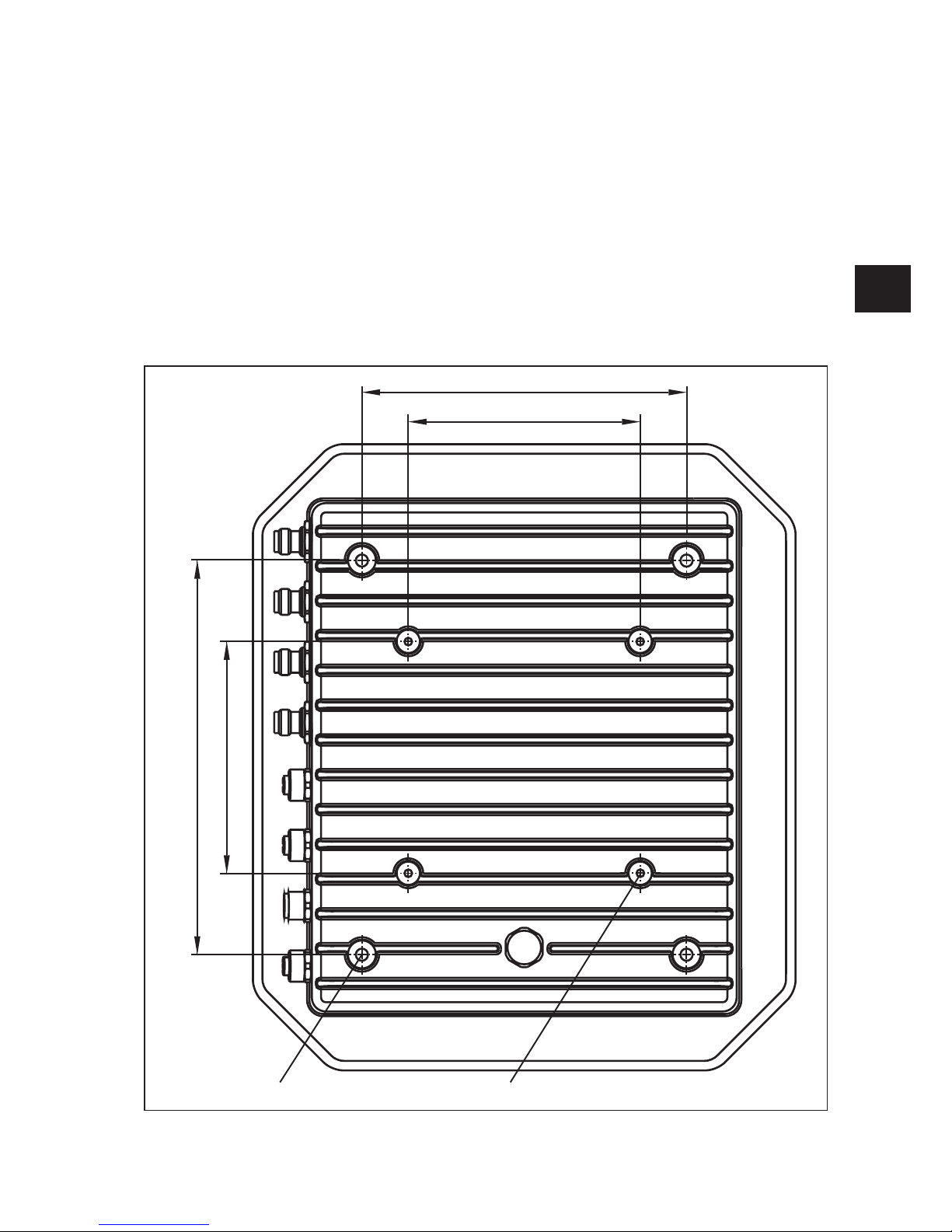
4.2 Installing the reader
The device has threaded holes at the rear for attaching the reader� The dimensions of the holes pattern
can be found in the drawing below� For ease of installation a bracket is available as an accessory, which
offers the option of mounting on a mast or wall�
M6
140
100
170
100
M4
Figure: Rear of the DTE with dimensions
8
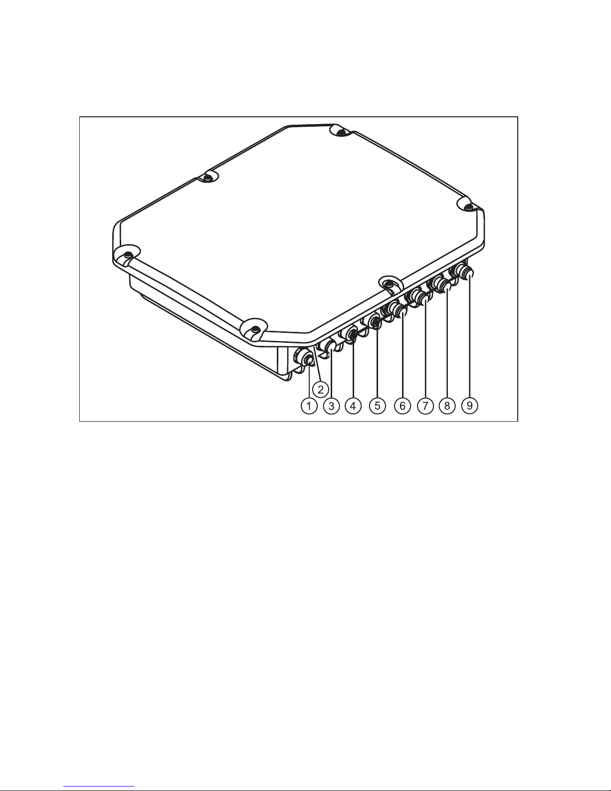
5 Connections and displays
The illustration below shows a DTE800 standard reader with all its connection options� Details of the connections and the pin assignments of plugs and sockets are provided in the following pages�
Figure: General view of the DTE
1: Communication connection: M12
2: Status indicators: 2 coloured LEDs (red, green)
3: Power supply connection: M12 male, 4-pin, A-coded
4: GPIO connection 1: M12 female, 5-pin, A-coded
5: GPIO connection 2: M12 female, 5-pin, A-coded
6: Antenna connection 1: R-TNC 50 Ohm
7: Antenna connection 2: R-TNC 50 Ohm
8: Antenna connection 3: R-TNC 50 Ohm
9: Antenna connection 4: R-TNC 50 Ohm
9
UK
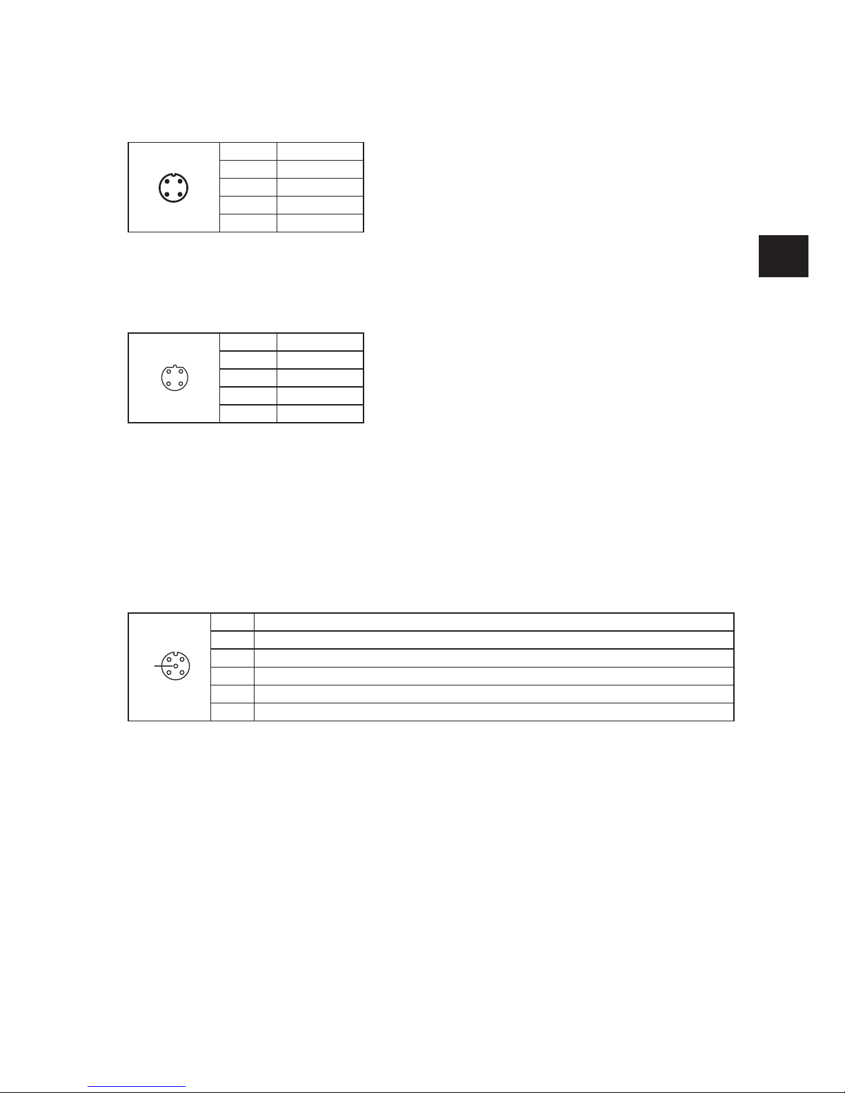
5.1 Power supply
The power supply is arranged as a four-pin round-pin plug with and M12 connection thread in A-coding�
4
2 1
3
Pin Assignment
1 + 24 V DC
2
3 GND
4
Only power supply units with power limitation are approved for operation with the device� This means that
the secondary side of the power supply unit is limited to a power of maximum 100 W�
5.2 Ethernet port
This data interface is arranged as a 4-pin M12 socket with D-coding� Only shielded cables may be used�
3
1 2
4
Pin Assignment
1 TD +
2 RD +
3 TD -
4 RD -
5.3 Digital inputs and outputs
The digital inputs and outputs are communicated via two five-pin sockets in A-coding with M12 connection
threads�
Note
Please note that the load per channel is limited to a maximum of 0�5 A, and the total load across all the
channels must not exceed 1�5 A� The inputs and outputs are designed for a maximum voltage of 30 V DC�
Further information can be found in the data sheet for the reader�
The activation and evaluation can be performed using the software ReaderStart v2, with the DLL supplied, or by access to the reader protocol�
3
1 2
4
5
Pin Assignment
1 VCC
2 Input
3 GND
4 Output
5 not connected
5.4 Antenna Connection
For the connection to the RFID antennas, the reader has four antenna connections that are of reverse
TNC design� Please only use the cable from the accessories or equivalent cable for this connection�
Note
Please only use cable suitable for the impedance (50 Ohm), as otherwise the performance of the reader
will be severely limited by the mismatch� If the mismatch is large, the reader may indicate a fault�

10
5.5 LED
The reader has a 2-colour LED for the indication of the operating state� The table below shows the colours used and the related operating state�
Red Green Operating State
X flashes approx� every 8 seconds Error during initialisation
X X Unit is booting
Flashes approx� every 8 seconds X Normal operation with heartbeat
Table: Indication of the operating states by the LED
5.6 Buzzer
Furthermore the reader is also fitted with a buzzer which, in addition to the LED, indicates successful
booting (1 x short) or an error (2 x long)�
11
UK
6 Software
For test purposes the reader can be operated using the software supplied� This software provides all the
necessary functionality of the reader for a test in a real environment� As an aid to configuration, various
basic settings for application scenarios are provided�
As well as this documentation, the following documents and programs can be found on the CD supplied:
● specification of the protocol for communication by the reader with a receiver
● API DLLs for the simplified activation of the reader with Borland and Visual Studio together with some
simple
● programming examples
● set-up program for the ifm electronic reader start software
● �Net Framework 4
● C++ 2008 redistributable
6.1 System requirements
To ensure correct operation using the software on your PC/laptop, your PC/laptop should meet the following minimum requirements:
Processor: X86 compatible
Memory: 512 MByte RAM
Operating system: Windows XP (SP3), Vista (SP1), Windows 7 or higher
free hard disk memory: 32Bit – 850 MByte (including Microsoft �Net Framework 4)
64Bit – 2 GByte (including Microsoft �Net Framework 4)
6.2 Installation
The software is installed by running "
ifm ReaderStart v2 Setup�exe"
from the CD-ROM supplied� During
the installation a check is made whether the necessary preconditions for the installation are satisfied�
This means that a check is made whether all the dependencies such as the necessary Windows Service
Packs, the �NET Framework in the respective version together with the C++ redistributables are installed�
If this is the case, during this process the demo software and the DLL for controlling the reader are installed�
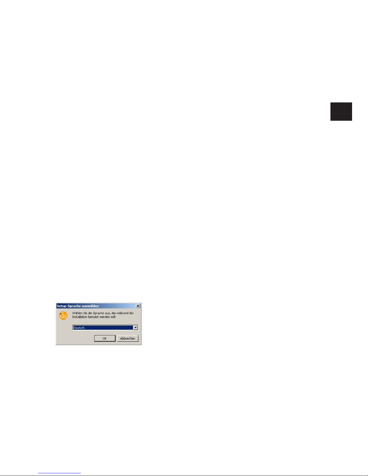
After the start of the set-up, you can change the language used during the installation in the window that
now opens� Confirm your selection by clicking on the OK button�
Figure: Language selection for the installation
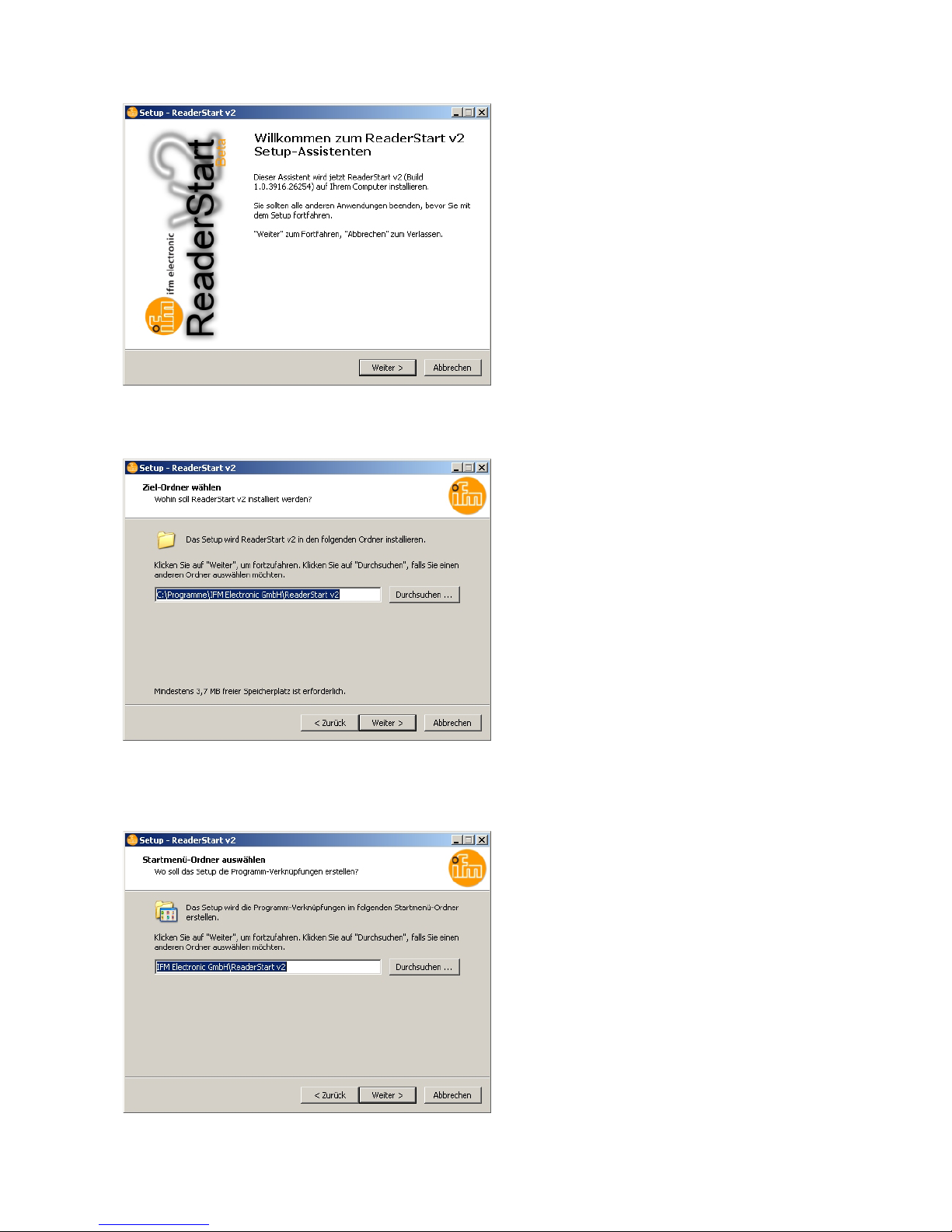
The welcome screen that now appears gives further information on the exact version of the reader start
software� This information can later be called up from the drop-down Info menu in the menu bar�
12
Figure: Welcome screen with software version
Press the Weiter (Next) button to select the target folder in which to install the software�
Figure: Selection of the installation folder
In the next screen you can customise the folder in the Windows start menu� Here, as in the previous windows, you are offered the standard settings�
Figure: Selection of the folder in the start menu
 Loading...