

IFM Electronic DTE101 Operating Instructions Manual
Operating instructions
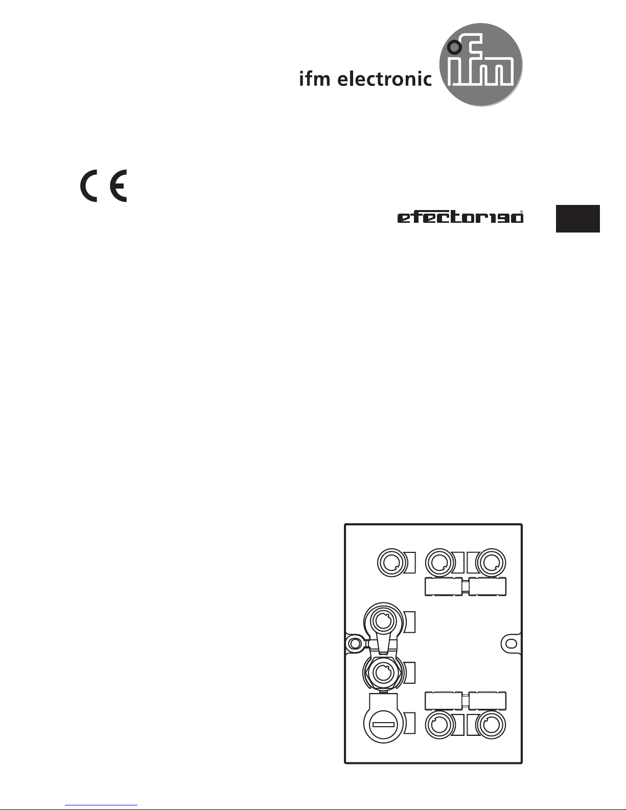
RFID evaluation unit
DTE101
80005398 / 01 06 / 2016
UK

2
Contents
1 Preliminary note ��������������������������������������������������������������������������������������������������� 4
1�1 Notes on this document ��������������������������������������������������������������������������������� 4
1�2 Symbols used ������������������������������������������������������������������������������������������������4
2 Safety instructions �����������������������������������������������������������������������������������������������4
2�1 General ���������������������������������������������������������������������������������������������������������� 4
2�2 Installation and connection ����������������������������������������������������������������������������4
2�3 Tampering with the device �����������������������������������������������������������������������������5
3 Functions and features ����������������������������������������������������������������������������������������5
3�1 Configuration via Ethernet interface ��������������������������������������������������������������5
3�2 RFID antennas ����������������������������������������������������������������������������������������������6
4 Function ��������������������������������������������������������������������������������������������������������������� 6
5 Installation������������������������������������������������������������������������������������������������������������6
5�1 Installation distance ���������������������������������������������������������������������������������������6
5�2 Installation orientation ������������������������������������������������������������������������������������7
5�3 Mounting options �������������������������������������������������������������������������������������������7
5�3�1 Mounting on DIN rail ����������������������������������������������������������������������������� 7
5�3�2 Removal �����������������������������������������������������������������������������������������������8
5�3�3 Mounting plate ��������������������������������������������������������������������������������������8
6 Electrical connection �������������������������������������������������������������������������������������������� 9
6�1 AUX voltage supply ��������������������������������������������������������������������������������������9
6�2 Field bus connection PROFINET IO Port 1 / Port 2 �������������������������������������10
6�2�1 Factory setting of the Ethernet parameters ����������������������������������������10
6�3 Process connections IO-1 ��� IO-4 ��������������������������������������������������������������� 11
6�4 Functional earth connection� �����������������������������������������������������������������������12
6�4�1 Mounting on DIN rail ��������������������������������������������������������������������������� 12
6�4�2 Mounting plate ������������������������������������������������������������������������������������12
7 Operating and display elements ������������������������������������������������������������������������13
7�1 Reset to factory settings ������������������������������������������������������������������������������13
7�2 LED indicators ���������������������������������������������������������������������������������������������13
7�2�1 LED AUX ��������������������������������������������������������������������������������������������13
7�2�2 LED PROFINET Port 1 / Port 2 ����������������������������������������������������������14
7�2�3 LED SF �����������������������������������������������������������������������������������������������14
7�2�4 LED BF �����������������������������������������������������������������������������������������������15

3
UK
Licences and trademarks
Microsoft® und Internet Explorer® are registered trademarks of Microsoft Cor-
poration� All trademarks and company names are subject to the copyright of the
respective companies�
7�2�5 LEDs IO1 ��� IO4 ���������������������������������������������������������������������������������15
7�2�6 Special device- LED indications ���������������������������������������������������������17
8 Technical data ���������������������������������������������������������������������������������������������������� 17
8�1 Data sheets �������������������������������������������������������������������������������������������������17
8�2 Device manual ��������������������������������������������������������������������������������������������� 17
9 Maintenance, repair and disposal ���������������������������������������������������������������������� 18
10 Approvals/standards ����������������������������������������������������������������������������������������18
11 Scale drawing ��������������������������������������������������������������������������������������������������18

4
1 Preliminary note
1.1 Notes on this document
This document applies to the RFID evaluation unit DTE101�
It is part of the device and contains information about the correct handling of the
product�
This document is intended for qualified electricians� These specialists are people
who are qualified by their training and their experience to see and to avoid possible hazards that may be caused during operation of the device�
Read this document before use to familiarise yourself with operating conditions,
installation and operation� Keep this document during the entire duration of use of
the device�
1.2 Symbols used
► Instructions
> Reaction, result
[…] Designation of pushbuttons, buttons or indications
→ Cross-reference
Important note
Non-compliance can result in malfunction or interference�
Information
Supplementary note
2 Safety instructions
2.1 General
► Observe these operating instructions�
► Adhere to the warning notes on the product�
Non-observance of the instructions, operation which is not in accordance with use
as prescribed below, wrong installation or incorrect handling can affect the safety
of operators and machinery�
2.2 Installation and connection
The device must only be installed, connected and put into operation by a qualified
electrician as the safe function of the device and machinery is only guaranteed
when installation is correctly carried out�The installation and connection must

5
UK
comply with the applicable national and international standards� Responsibility lies
with the person installing the device�
This is a class A product� The device may cause radio interference in
domestic areas� In this case it can be necessary for the user to take appropriate measures�
2.3 Tampering with the device
Tampering with the device is not allowed and will lead to an exclusion of liability
and warranty� Tampering with the device can affect the safety of operators and
machinery�
► Do not open the device�
► Do not insert any objects into the device�
► Prevent metal foreign bodies from penetrating�
3 Functions and features
The RFID evaluation unit DTE101 integrates a PROFINET IO interface and 4
channels for the connection of field devices� Each channel can be used either for
the connection of an RFID antenna or as input/output to IEC 61131�
The device
• controls the data exchange to the RFID antennas or the sensor/actuator level�
• communicates with the higher-level control level via PROFINET IO�
• allows device configuration via a web server�
Application examples:
• Material flow control in production lines
• Warehouse management by the automatic detection of stored products
• Tank management, order picking or product tracking
3.1 Configuration via Ethernet interface
• 10 Mbps and 100 Mbps
• TCP / IP - Transport Control Protocol / Internet Protocol
• UDP - User Datagram Protocol
• IT functionality: HTTP server
• M12, twisted pair
6
3.2 RFID antennas
The device supports up to four RFID read/write heads of type ANT41x / ANT51x
from ifm electronic gmbh�
You can find information about the matching read/write heads on our website at:
www�ifm�com
→ data sheet search → ANT41 or ANT51
4 Function
You can find detailed information about the function of the system in the device
manual at:
www�ifm�com
→ data sheet search → DTE101 → Operating instructions
5 Installation
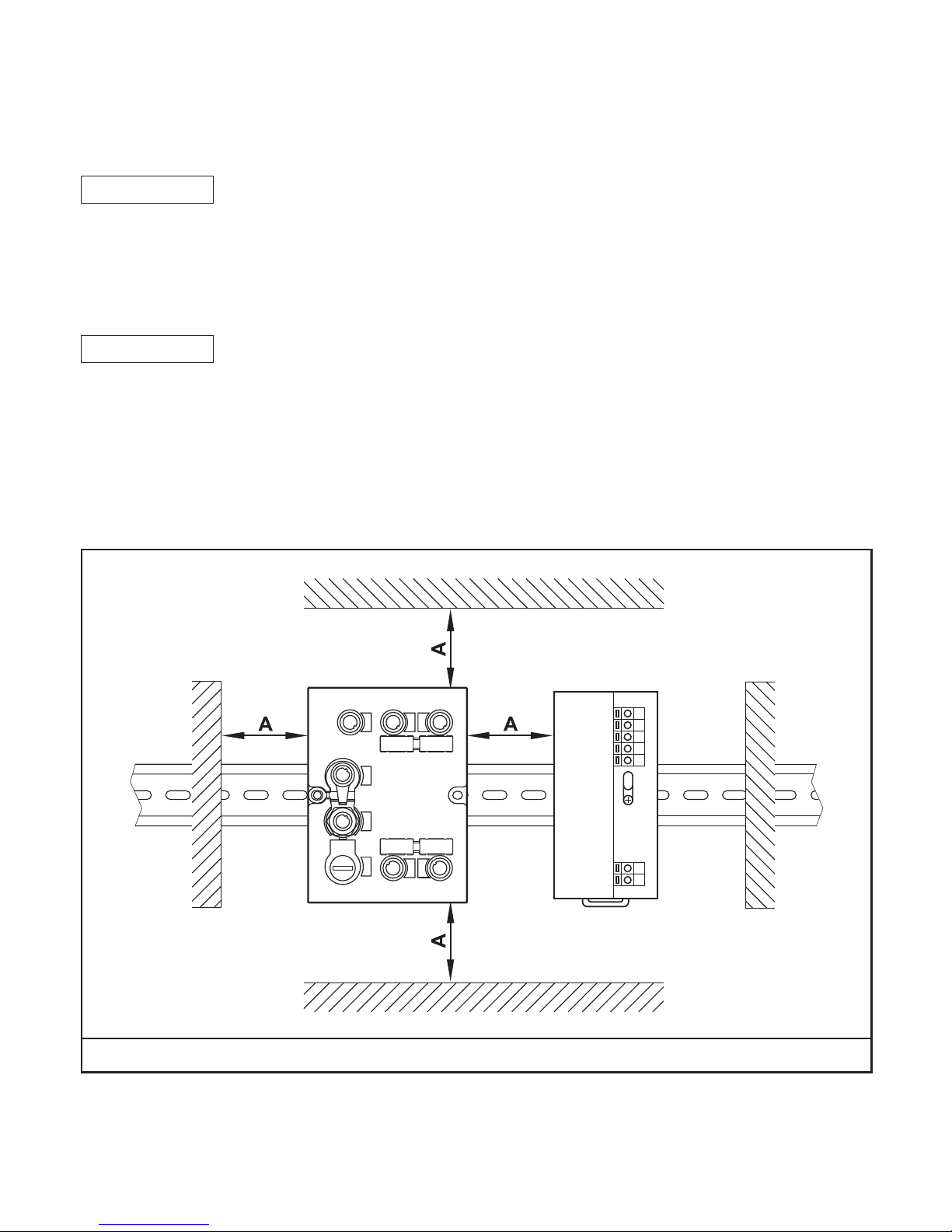
5.1 Installation distance
Due to the internal heating of the device a minimum distance to other objects of
10 mm is to be taken into account during installation�
A = 10 mm
 Loading...