

IFM Electronic DI5029, DI5030 Installation Instructions Manual
Installation instructions
Compact speed monitor M18
DC design, IO-Link, with connector
DI5029
DI5030
UK
706454 / 00 10 / 2017

Contents
1 Preliminary note ��������������������������������������������������������������������������������������������������� 3
1�1 Symbols and warnings used �������������������������������������������������������������������������3
2 Safety instructions �����������������������������������������������������������������������������������������������4
3 Functions and features ����������������������������������������������������������������������������������������4
4 Function diagrams �����������������������������������������������������������������������������������������������4
4�1 Single point mode ����������������������������������������������������������������������������������������� 4
4�2 Window mode ����������������������������������������������������������������������������������������������� 5
5 SIO mode�������������������������������������������������������������������������������������������������������������7
5�1 Switching function normally open ����������������������������������������������������������������� 7
5�2 Switching function normally closed ���������������������������������������������������������������7
6 IO-Link mode �������������������������������������������������������������������������������������������������������7
6�1 LED display ��������������������������������������������������������������������������������������������������8
6�2 Setting parameters via IO-Link ��������������������������������������������������������������������8
6�2�1 Setting range and conditions for parameter setting ���������������������������� 10
6�2�2 Start-up delay ������������������������������������������������������������������������������������� 11
6�2�3 Background compensation ����������������������������������������������������������������� 11
6�2�4 Teach offset ���������������������������������������������������������������������������������������� 11
6�2�5 Prescaler �������������������������������������������������������������������������������������������� 11
6�3 Diagnostics and events ������������������������������������������������������������������������������12
7 Installation����������������������������������������������������������������������������������������������������������13
7�1 Tips on flush and non-flush mounting in metal �������������������������������������������13
8 Electrical connection ������������������������������������������������������������������������������������������ 14
8�1 Wiring ���������������������������������������������������������������������������������������������������������14
9 Operation ����������������������������������������������������������������������������������������������������������� 15
10 Scale drawing ��������������������������������������������������������������������������������������������������15
2
1 Preliminary note
This document applies to devices of the type "compact speed monitor" (art� no�:
DI5029 and DI5030)�
This document is intended for specialists� These specialists are people who are
qualified by their training and their experience to see risks and to avoid possible
hazards that may be caused during operation, installation or maintenance of the
device�
Read this document before use to familiarise yourself with operating conditions,
installation and operation� Keep this document during the entire duration of use of
the device�
WARNING
Adhere to the warning notes and safety instructions (→ 2 Safety instructions)�
1.1 Symbols and warnings used
► Instructions
→ Cross-reference
Information
Supplementary note�
Important note
Non-compliance may result in malfunction or interference�
UK
WARNING
Warning of serious personal injury�
Death or serious irreversible injuries may result�
3
2 Safety instructions
A qualified electrician must connect the unit� Observe the national and
international regulations for the installation of electrical equipment�
3 Functions and features
The inductive compact speed monitor with IO-Link determines the frequency
[pulses/min] with which the sensor is damped without contact� The device
compares the measured value with the switching thresholds and switches the
outputs according to the configuration� The device can be operated in the IO-Link
mode or in the SIO mode (switching output)�
4 Function diagrams
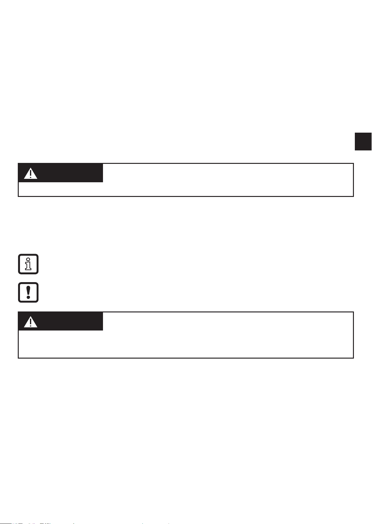
4.1 Single point mode
Normally open (switch point logic = 1)
SP1: switch-off point
SP1+hyst: switch-on point
The "open" output status indicates that a set rotational speed has not been
reached�
Normally closed (switch point logic = 0)
SP1: switch-on point
SP1+hyst: switch-off point
The "closed" output status indicates that a set rotational speed has not been
reached�
4
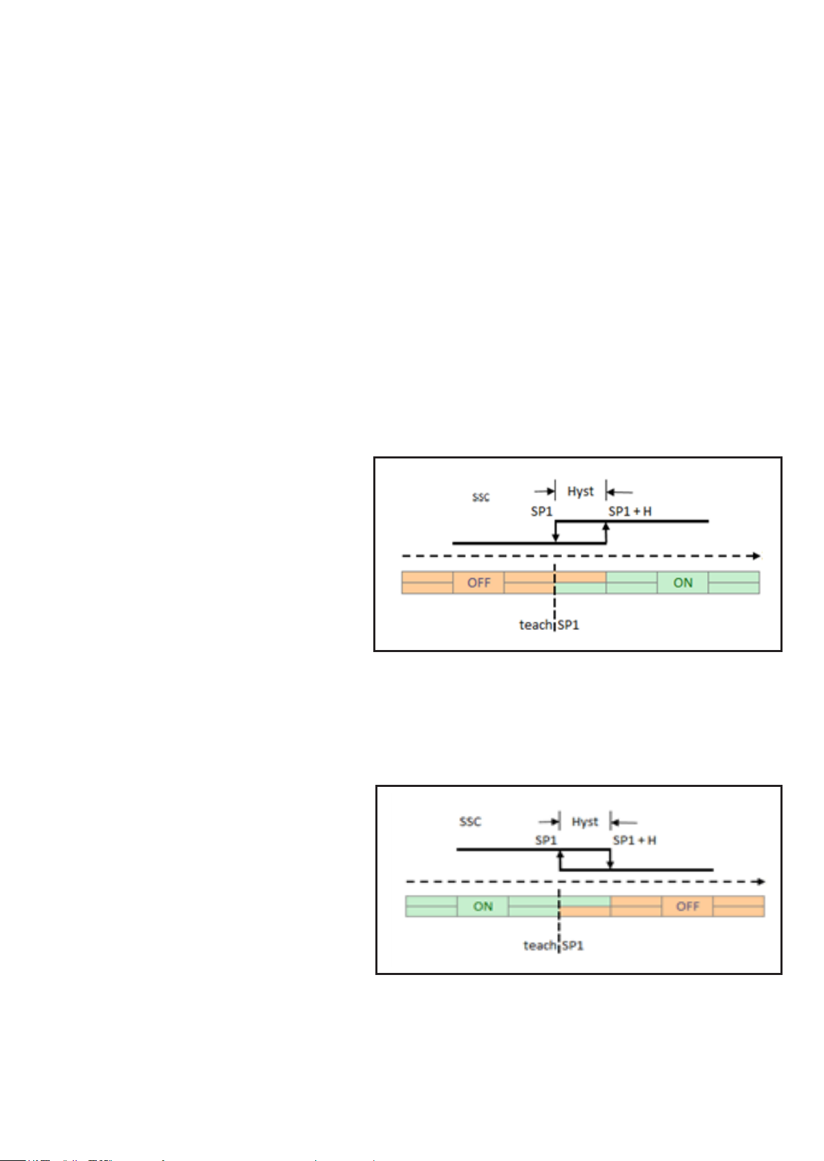
1
2
3
4
1: Power-on delay time
2: Start-up delay
UK
3: Normally open
4: Normally closed
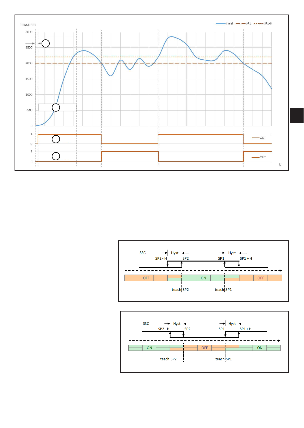
4.2 Window mode
Normally open (switch point logic
= 1)
SP1: switch-on point window
SP1+hyst: switch-off point
SP2: switch-on point window
SP2 hyst: switch-off point
Normally closed (switch point logic
= 0)
SP1: switch-off point window
SP1+hyst: switch-on point
SP2: switch-off point window
SP2 hyst: switch-on point
5
 Loading...