

IFM Electronic DI5020, DI5026, DI5021 DI5022, DI520A, DI523A Installation Instructions Manual
Page 1
Installation instructions
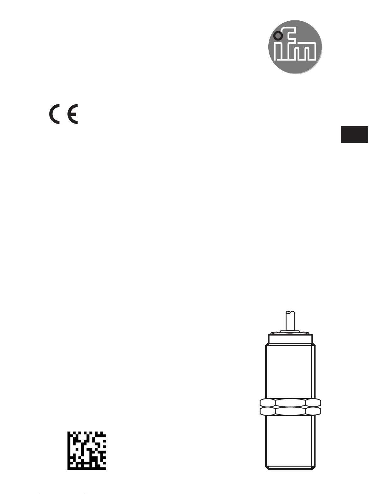
Compact speed monitor M30
DC version
DI502x
DI52xA
80258280 / 00 12 / 2016
UK
Page 2

2
Contents
1 Preliminary note ��������������������������������������������������������������������������������������������������� 3
1�1 Symbols and warnings used �������������������������������������������������������������������������3
2 Safety instructions �����������������������������������������������������������������������������������������������4
2�1 ATEX units (DI52xA) ������������������������������������������������������������������������������������� 4
3 Functions and features ����������������������������������������������������������������������������������������4
3�1 Switching function normally open ����������������������������������������������������������������� 4
3�2 Switching function normally closed ���������������������������������������������������������������4
3�3 Damping ������������������������������������������������������������������������������������������������������5
3�4 Function diagram ������������������������������������������������������������������������������������������ 5
3�5 IO-Link ����������������������������������������������������������������������������������������������������������6
4 Mounting ������������������������������������������������������������������������������������������������������������� 6
5 Electrical connection �������������������������������������������������������������������������������������������� 7
5�1 Wiring �����������������������������������������������������������������������������������������������������������7
6 Setting������������������������������������������������������������������������������������������������������������������7
6�1 Setting for switching function normally open ������������������������������������������������8
6�2 Setting for switching function normally closed ���������������������������������������������� 8
7 Operation ������������������������������������������������������������������������������������������������������������� 8
8 Technical data ������������������������������������������������������������������������������������������������������ 9
Page 3
3
UK
1 Preliminary note
This document applies to devices of the type "compact speed monitor" (art� no�:
DI502x and DI52xA)�
This document is intended for specialists� These specialists are people who are
qualified by their training and their experience to see risks and to avoid possible
hazards that may be caused during operation, installation or maintenance of the
device�
Read this document before use to familiarise yourself with operating conditions,
installation and operation� Keep this document during the entire duration of use of
the device�
WARNING
Adhere to the warning notes and safety instructions (→ 2 Safety instructions)�
1.1 Symbols and warnings used
► Instructions
→ Cross-reference
Information
Supplementary note
Important note
Non-compliance may result in malfunction or interference�
WARNING
Warning of serious personal injury�
Death or serious irreversible injuries may result
Page 4

4
2 Safety instructions
A qualified electrician must connect the unit� Observe the national and
international regulations for the installation of electrical equipment�
2.1 ATEX units (DI52xA)
Remarks for safe use in hazardous areas: operating instructions (Ex protection
related part) for speed monitors according to EU directive 2014/34/EU annex VIII
(ATEX) group II, equipment category 3D�
If no operating instructions (Ex protection related part) or EC declaration of
conformity are supplied with this product in the language of the EU user country,
these can be requested from your dealer (see delivery note) or manufacturer (see
cover sheet / back)�
The ATEX protection is ensured even without mechanical protection�
3 Functions and features
The compact, non-contact inductive speed monitor detects when a speed drops
below a pre-set value and signals this with a switched output�
3.1 Switching function normally open
Transistor output LED
green
switched (conducting) on rotational speed > SP + Hy and during the start-
up delay
not switched (non conducting) off rotational speed < SP
SP = switch point
Hy = hysteresis
3.2 Switching function normally closed
Transistor output LED
green
not switched (non conducting) off rotational speed > SP + Hy and during the start-
up delay
switched (conducting) on rotational speed < SP
SP = switch point
Hy = hysteresis
Switching functions of the units (→ 8 Technical data)
Page 5

5
UK
3.3 Damping
The yellow LED indicates the damping status of the sensor irrespective of either
the switching function or the switching status of the transistor output�
Sensor LED yellow
undamped off
damped on
3.4 Function diagram
SP + Hy
SP
1
2
3
4
[Imp/min]
[s]
1: Voltage supply
2: Start-up delay
3: Switching function normally open
4: Switching function normally closed
SP = switch point
Hy = hysteresis
= transistor output switched (conducting)
The start-up delay suppresses an error signal as long as the machine is in
the process of starting and has not yet reached its minimum speed� After
application of the operating voltage the start-up delay is active only once�
If the plant is started and stopped frequently, linking the drive and speed
monitor power supplies ensures that the start-up delay is effective each
time the machine is switched on�
Page 6

6
3.5 IO-Link
IO-Link allows the configuration of internal parameters such as start-up delay
and switching behaviour (normally closed/normally open) as well as reading the
current measured values� Furthermore IO-Link protects against signal faults and
measured value losses as well as tampering with the sensor�
You will find the IODDs necessary for the configuration of an IO-Link device
and detailed information about parameter setting tools, process data structure,
diagnostic information and parameter addresses at www�ifm�com/gb/io-link�
4 Mounting
Mounting principle Mounting specifications
► Fix the unit using a bracket and secure it by means of the nuts provided so that
it cannot work loose�
Flush installation�
► Adhere to the above mounting specifications to ensure a correct function�
Nominal sensing range Sn (→ 8 Technical data)
Page 7

7
UK
5 Electrical connection
► Disconnect power�
► Connect the device according to the wiring diagram�
5.1 Wiring
BN
BK
BU
L
+
L
DI5020, DI5021 DI5022, DI520A
BK = black
BN = brown
BU = blue
L
L
+
BN
BK
BU
L
L
+
BN
BK
BU
DI5026, DI523A
BK = switching output / IO-Link / PNP / NPN programmable
6 Setting
1
2
2
1: Multi-turn potentiometer for switch point
setting (without end stop)
2: LEDs:
Green LED for switching status
indication
(→ 3.1 Switching function normally
open)
Yellow LED for damping indication (input
signal)
(→ 3.3 Damping)
Operating and display elements
Page 8

8
► Keep the minimum speed to be monitored in the plant on a constant level�
► Connect the device to supply voltage�
► Wait until the start-up delay is over (→ 8 Technical data)�
► Set the switch point depending on the status of the green LED�
6.1 Setting for switching function normally open
When the green LED does not light:
- Turn the pot slowly anticlockwise (-) until the green LED lights�
Setting is finished�
When the green LED lights:
- Turn the pot clockwise (+) until the green LED goes out�
- Turn the pot slowly anticlockwise (-) until the green LED lights�
Setting is finished�
6.2 Setting for switching function normally closed
When the green LED lights:
- Turn the pot slowly anticlockwise (-) until the green LED goes out�
Setting is finished�
When the green LED does not light:
- Turn the pot clockwise (+) until the green LED lights�
- Turn the pot slowly anticlockwise (-) until the green LED goes out�
Setting is finished�
7 Operation
The operation is maintenance-free�
Ensure the following for a correct function:
► Keep the sensing face and the clear space free of metal deposits and foreign
bodies�
► Do not operate units with high field intensity (e�g� mobile phones) at close
range to the speed monitor�
Page 9

9
UK
8 Technical data
80
75,5
M30x1,5
5,4
2,2
36
5
Dimensions [mm]
DI5020
DI5021
DI5022
DI5026
DI520A
DI523A
Nominal voltage [V] 10���36 DC
Current consumption [mA] < 20 < 22 < 20 < 22
Current rating [mA] 250
Voltage drop [V] < 2�5
Reverse polarity
protection
yes
Short-circuit protection yes
Overload protection yes
Nominal sensing range
(Sn)
[mm] 10
Operating distance [mm] 0���8�1
Setting range [pulses/
min]
5���3600
Via potentiometer
● ● ● ○ ● ○
Via IO-Link - - -
○
-
○
Hysteresis [% of SP] 10
Damping frequency [pulses/
min]
≤ 18000
Switching function NO
●
-
● ○ ● ○
Switching function NC -
●
-
○
-
○
Page 10

10
DI5020
DI5021
DI5022
DI5026
DI520A
DI523A
Start-up delay [s] 15 5 0 0���30 15 0���30
Ambient temperature [°C] -25���80 -20���60
Protection IP 65 / IP 67 / III
ATEX equipment
category
- 3D
IO-Link - - -
●
-
●
Connection PUR cable / 2 m; 3 x 0�5 mm²
● = applicable
○
= programmable
- = not applicable
Data sheets and EC declarations of conformity can be found at:
www.ifm.com → Data sheet search→ Article number
 Loading...