

Page 1

Geräte-Handbuch
Device manual
CANmem
Datenspeicher/-logger
für CANopen-Netzwerke
Data memory and logger
for CANopen networks
CR3101
DEUTSCHENGLISH
Sachnr.: 7390584/00 10/2006
R
CARD ERROR
CARD ACCESS
ON
ERROR
CAN
Page 2

Inhalt
1. Bestimmungsgemäße Verwendung . . . . . . . . . . . . . . . . . . . . . . . Seite 3
2. CAN-Kommunikation im Überblick . . . . . . . . . . . . . . . . . . . . . . . Seite 4
3. Technische Daten . . . . . . . . . . . . . . . . . . . . . . . . . . . . . . . . . . . . Seite 5
4. Montage . . . . . . . . . . . . . . . . . . . . . . . . . . . . . . . . . . . . . . . . . . Seite 6
5. Elektrischer Anschluss . . . . . . . . . . . . . . . . . . . . . . . . . . . . . . . . . Seite 7
6. Speicherkarten
SD-/MMC-Karte . . . . . . . . . . . . . . . . . . . . . . . . . . . . . . . . . . . . . Seite 8
PCMCIA-Karte . . . . . . . . . . . . . . . . . . . . . . . . . . . . . . . . . . . . . . Seite 9
7. Parameter- und EMCY-Objekt-Übersicht . . . . . . . . . . . . . . . . . . . . Seite 11
8. Betriebsanzeige (Status-LEDs). . . . . . . . . . . . . . . . . . . . . . . . . . . . Seite 12
9. Objektverzeichnis
Herstellerspezifische Profile; Index 2000 bis 5FFF. . . . . . . . . . . . . . Seite 13
Kommunikationsprofile; Index 1000 bis 1FFF . . . . . . . . . . . . . . . . Seite 19
10. Hinweise zur Programmierung. . . . . . . . . . . . . . . . . . . . . . . . . . . Seite 22
11. Wartung, Instandsetzung und Entsorgung . . . . . . . . . . . . . . . . . . Seite 24
12. Komformitätserklärung . . . . . . . . . . . . . . . . . . . . . . . . . . . . . . . . Seite 24
13. Begriffe und Abkürzungen . . . . . . . . . . . . . . . . . . . . . . . . . . . . . Seite 25
CANMEM CR3101
2
Sicherheitshinweise
Diese Beschreibung ist Bestandteil des Gerätes. Sie enthält Texte
und Abbildungen zum korrekten Umgang mit dem Modul und
muss vor einer Installation oder dem Einsatz gelesen werden.
Befolgen Sie die Angaben der Dokumentation. Nichtbeachten der Hinweise,
Verwendung außerhalb der nachstehend genannten bestimmungsgemäßen
Verwendung, falsche Installation oder Handhabung können Beeinträchtigungen der Sicherheit von Menschen und Anlagen zur Folge haben.
Das Gerät darf nur von einer Elektrofachkraft eingebaut, angeschlossen und
in Betrieb gesetzt werden.
Schalten Sie das Gerät extern spannungsfrei bevor Sie irgendwelche Arbeiten
an ihm vornehmen. Schalten Sie ggf. auch unabhängig versorgte Ausgangslastkreise ab.
Bei Fehlfunktion des Geräts oder bei Unklarheiten setzen Sie sich bitte mit
dem Hersteller in Verbindung. Eingriffe in das Gerät können schwerwiegende
Beeinträchtigungen der Sicherheit von Menschen und Anlagen zur Folge haben. Sie sind nicht zulässig und führen zu Haftungs- und Gewährleistungsauschluss.
Page 3
1. Bestimmungsgemäße Verwendung
CANmem bietet die Möglichkeit Prozessdaten einer laufenden Applikation auf
SD-,MMC- oder PCMCIA-Speicherkarten abzulegen. Bereits gespeicherte Vorgabewerte (Anlagenparameter, Sollwerttabellen, etc.) können in die Steuerung geladen werden.
Das Gerät ist direkt in der Maschine bzw. in der mobilen Anlage einsetzbar. Die
CAN-Anbindung und die 10...30 V DC Spannungsversorgung erfolgt dabei über
einen 5-poligen M12-Rundstecker.
Applikationen im Überblick
■ Parametrierung mobiler Maschinen und Anlagen
■ Zwischenspeicherung von Ferndiagnosedaten
■ Speicherung von Alarm- und Fehlermeldungen (Black-Box-Funktion)
■ Auslesen von Betriebsdaten aus der laufenden Maschine
■ Ein- und Auslesen von Datenblöcken aus dem Arbeitsspeicher
Zum CANmem sind drei Softwaretools erhältlich:
• CANmem Configurator (Konfiguration und Strukturierung der Speicherkarte),
• CANmem Downloader (Aktualisieren bzw. Laden von Betriebssystemen),
• CANmem Reader (Auslesen und Konvertierung der gespeicherten Daten).
Die Beschreibung dieser Tools entnehmen Sie bitte dem jeweiligen Programm-
handbuch. Als Download-File im PDF-Format steht eine Zusammenfassung der
Handbücher im Internet unter „www.ifm-electronic.com“ zur Verfügung.
➔ Datenblatt direkt ➔ CR3101 ➔ weitere Informationen
www.ifm-electronic.com
DEUTSCH
CANMEM CR3101
3
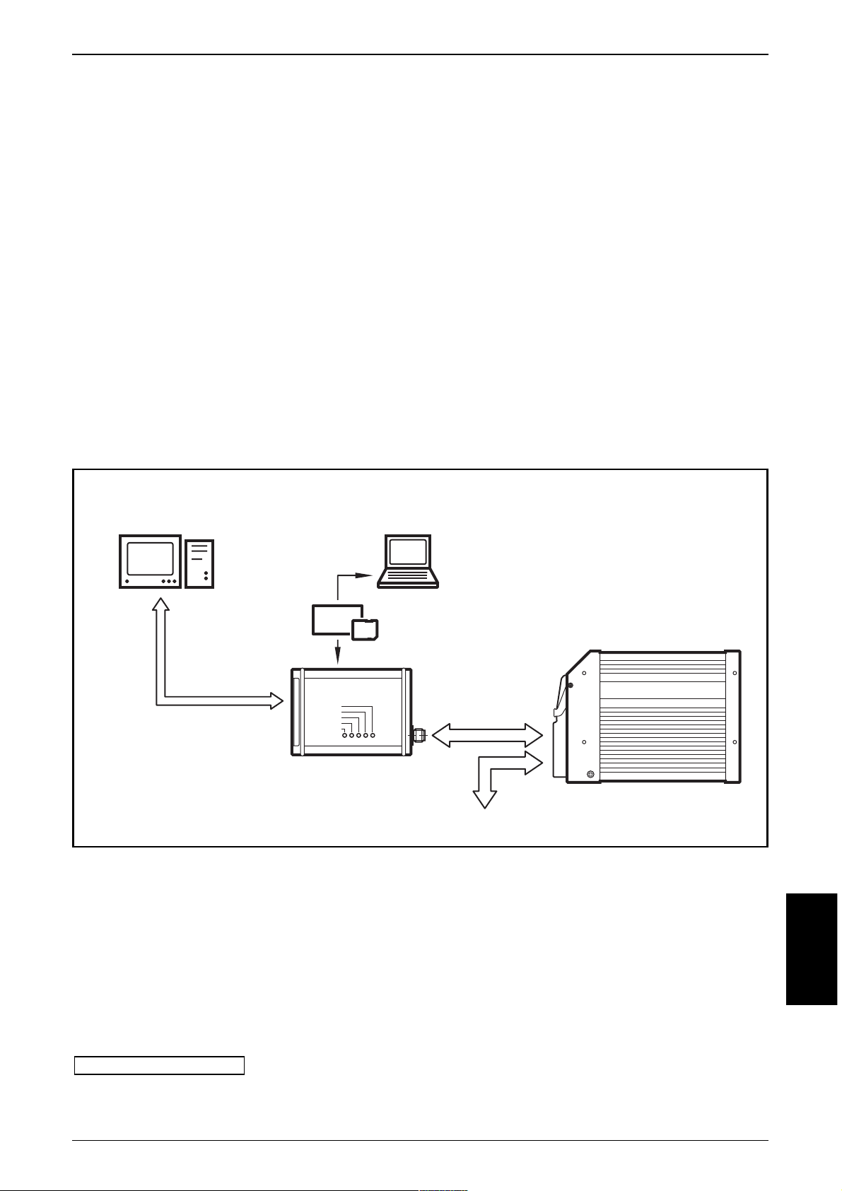
PC
Vorgabewerte übertragen
Prozeßdaten auswerten
Betriebssystem laden
oder Notebook mit
SD-/PCMCIA-Slot
TOP
USB
CARD ERROR
CARD ACCESS
ON
ERROR
CAN
CANmem
Vorgabewerte übertragen
Prozeßdaten auswerten
SD-/MMC- oder
PCMCIA-Card
CAN-Bus
Sensorik/Aktorik
Steuerung
Page 4

2. CAN-Kommunikation im Überblick
CANmem enthält ein Objektverzeichnis und unterstützt die Kommunikationsmechanismen gemäß CiA DS301 Version 4.0. Der Datenaustausch (Schreiben und
Lesen) wird über Einträge im Objektverzeichnis parametriert.
• Es sind 1 Server SDO und 8 Receive PDOs gemäß CiA DS 401 eingerichtet.
Die Default-IDs sind entsprechend des „Predefined connection set“ vergeben.
Das Gerät unterstützt kein dynamisches „PDO-Mapping“.
• Die COB-IDs der einzelnen PDOs sind konfigurierbar.
Geänderte PDOs (PDO-linking) werden spannungsausfallsicher gespeichert.
• Das Modul erwartet ein Synch-Objekt.
Der CAN-Identifier des Synch-Objektes ist konfigurierbar. Nach einer Änderung
wird der ID automatisch spannungausfallsicher gespeichert.
• Das Modul unterstützt „Node guarding“.
Die „Guard time“, der „Life time factor“ und der CAN-Identifier des Guard Objektes sind konfigurierbar und werden spannungsausfallsicher gespeichert.
• Das Modul generiert ein Emergency Objekt.
Der COB-ID des EMCY-Objektes ist konfigurierbar.
• Das Modul speichert die 4 zuletzt aufgetretenen Fehler.
Abgelegt wird der Fehlercode des jeweiligen Emergency Objektes.
• Das Modul unterstützt eine Reset-Funktion;
d.h. die Belegung der Parameter mit den werkseitigen Default-Werten*.
• Die Artikel-Nr., die HW- und SW-Version sind im Objektverzeichnis hinterlegt
und können ausgelesen werden.
*) Werkseitige Default-Einstellungen
→ 7. Parameter- und EMCY-Objekt-Übersicht → Parameterliste
CANMEM CR3101
4
Page 5

3. Technische Daten
DEUTSCH
CANMEM CR3101
5
z.B. Parametrierung mobiler Maschinen und Anlagen;
Speicherung von Ferndiagnosedaten oder Alarm- und Fehlermelungen
Aluminium
130 x 85 x 35 mm
mit Montagelaschen
(Befestigungslöcher in den Seitenflächen vorbereitet,
siehe Montagevarianten)
IP 65
-20...+80 °C (Speicherkarte je nach Typ)
-40...+80 °C (Speicherkarte je nach Typ)
250 g
10...30 V DC
Versorgung über M12-Steckverbinder
120 mA (bei 24 V DC)
CAN Interface 2.0 B, ISO 11898
M12-Steckverbinder für Betriebsspannung und CAN-Bus, 5-polig (Typ Lumberg)
CAN galvanisch entkoppelt
20 kBit/s...1 MBit/s (Defaulteinstellung 125 kBit/s)
CANopen, CiA DS 301 Version 3.0
hex 20 (= 32)
USB 2.0 (1.1 kompatibel), Typ Mini-B (Buchse)
für PC-Kommunikation, Konfiguration und Firmware-Update
Windows 2000, ME, XP
Secure Digital (SD) oder Multi Media Card (MMC)
für SRAM PC-Card Typ I bis 16 MByte (bevorzugt 1 MByte )
ermöglicht exakte Datenauswertung durch Zeitstempel
z.B. für den Einsatz als Fehlerspeicher oder Unfalldatenschreiber (Black-Box)
Speicherkarten Fehler (CARD ERROR)
Speicherkarten Zugriff (CARD ACCESS)
Betriebsspannung (ON)
Kommunikationsfehler (ERROR)
CAN-Modus (CAN)
\DATEN\100\DB-FORM—PZD/03/12/96
CR3101
CANmem
Datenspeicher und -logger
Einsatz von
SD-/MMC-Speicherkarten
und Karten nach
PCMCIA-Standard
Parametrierung
über IEC 61131
10...30 V DC
Verwendung
Mechanische Daten
Gehäuse
Maße (Bx H x T)
Montage
Schutzart
Betriebstemperatur (Gerät)
Lagertemperatur (Gerät)
Gewicht
Elektrische Daten
Betriebsspannung
Stromaufnahme
Schnittstellen
CAN Schnittstelle
Baudrate
Kommunikationsprofil
Node-ID (Default)
USB Schnittstelle
PC-Systemvoraussetzungen
SD-/MMC-Slot
PCMCIA-Slot
Sonstiges
Integrierte Echtzeituhr
Anzeigen (Status-LEDs)
1) CANopen Schnittstelle
2) Verschlussklappe
3) USB Schnittstelle
4) SD-/MMC-Slot
5) PCMCIA-Slot
ERROR
CAN
117,5
ON
5 LED
130
35
CARD ERROR
85
1
CARD ACCESS
2
3
5
4
M12x1
Page 6
CANMEM CR3101
6
USB-Verbindungskabel
Typ A – Typ Mini-B
Länge 1,8 m
Bestell-Nr. EC2058
SRAM-Speicherkarte (PCMCIA Typ I); 1 MByte
Bestell-Nr. EC1020
CANmem
(Konfigurator- und Auswertesoftware)
Bestell-Nr. CP9012
Die Software erhalten Sie kostenlos auf Anfrage
oder als Download im Internet unter „www.ifm-electronic.com“
ifm electronic gmbh • Teichstraße 4 • 45 127 Essen 09.10.2006Technische Änderungen behalten wir uns ohne Ankündigung vor! CR3101-AB / Seite 2
CARD ERROR
CARD ACCESS
ON
ERROR
CAN
CR3101
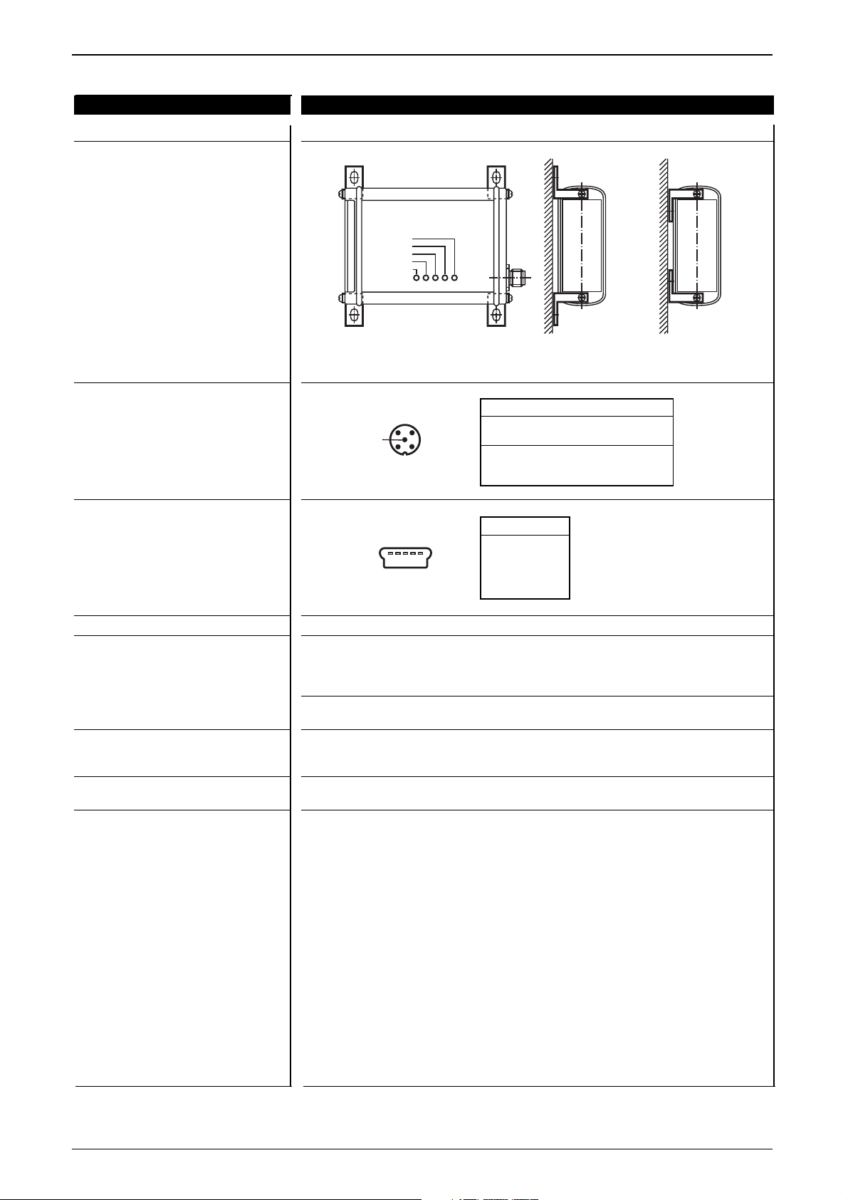
Montagevarianten
Anschlussbelegung CAN
(5-pol. M12-Steckverbinder)
Anschlussbelegung USB
(5-pol. Typ Mini-B)
Zubehör
(gesondert zu bestellen)
Software
Hinweis
2
43
1
5
Bezeichnung Pin Potential
Betriebsspannung 1 GND
2 10...30 V DC
CAN-Interface 3 CAN_GND
4 CAN_H
5 CAN_L
Pin Potential
1+ 5 V
2 Data –
3 Data +
4 ID (n.c.)
5 GND
Variante A Variante B
54321
Page 7
DEUTSCH
CANMEM CR3101
7
4. Montage
Entfernen Sie zur Anbringung der Montagelaschen jeweils die 2 Abdeckkappen
in den Seitenflächen des Datenspeichers.
Die Schrauben unter den Abdeckkappen dienen zur Befestigung der Montagelaschen. Wählen Sie, dem Platzangebot entsprechend, die für Sie geeignete Befestigungsvariante A oder B (→ 3. Technische Daten, Montagevarianten).
5. Elektrischer Anschluss
Um den elektrischen Störschutz sicherzustellen, muss das CANmem-Gehäu-
se mit der Fahrzeugmasse leitend verbunden werden. Dies ist z.B. gewährleistet, wenn das Gerät mit den beiliegenden Montagelaschen an leitenden Fahrzeugteilen befestigt wird.
Da die CAN-Schnittstelle des CANmems galvanisch entkoppelt ist, muss das
Potential „CAN_GND“ aller CAN-Teilnehmer gebrückt sein. Andernfalls ist
eine sichere Gerätefunktion nicht gewährleistet oder die CAN-Schnittstelle kann
ggf. zerstört werden.
Das Potential „GND“ der Betriebsspannung ist zusätzlich separat zu führen.
Die DC-Versorgungsleitungen dürfen eine Länge von 10 m nicht überschrei-
ten.
Hinweise zur Klassifizierung beachten → 12. Konformitätserklärung
Anschlussbelegung → 3. Technische Daten, Anschlussbelegungen
USB-Schnittstelle
Über die USB-Schnittstelle kann CANmem als Speicherkartenlesegerät verwendet
werden. Hierzu wird der„CANmem Configurator“ und das USB Verbindungskabel
benötigt (→ 3. Technische Daten, Zubehör).
➔ Datenblatt direkt ➔ CR3101 ➔ Zubehör
Ein Firmware-Update wird prinzipiell über USB mit dem „CANmem Downloader“
durchgeführt.
www.ifm-electronic.com
Page 8
6. Speicherkarte (nicht im Lieferumfang enthalten)
Beachten Sie die Angaben des Speicherkarten-Herstellers.
Schalten Sie CANmem aus, wenn Sie eine Speicherkarte einsetzen oder entfernen.
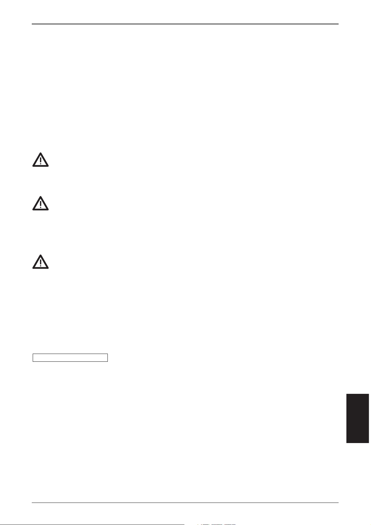
Öffnen der Verschlussklappe
Die Verschlussklappe ist mit einem speziellen Federscharnier ausgestattet.
Beim Öffnen muss ein leichter Druck auf das Scharnier ausgeübt werden.
Im montierten Zustand kann hierfür z.B. ein Schraubendreher oder ein ähnlicher
flacher Gegenstand genutzt werden.
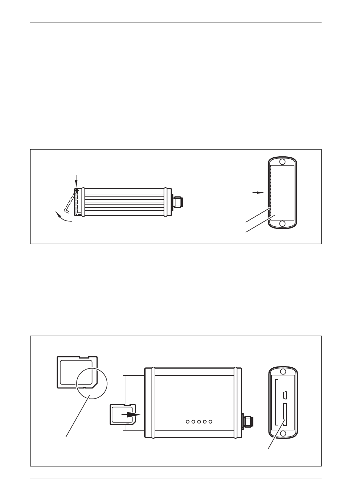
SD-/MMC-Karte
Einsetzen:
Vor dem Einsatz von SD-Karten den mechanischen Schreibschutz entriegeln.
Karte vorsichtig bis zum Einrasten in den SD-/MMC-Slot schieben.
Entnehmen:
Karte vorsichtig bis zum hörbaren Lösen der Arretierung in das Gerät drücken
und loslassen.
CANMEM CR3101
8
SD-/MMC-Karte
SD-/MMC-Slot
Lage
der Abschrägung
und Arretierung
Federscharnier
Verschlussklappe
Druckrichtung
Druckrichtung
Page 9
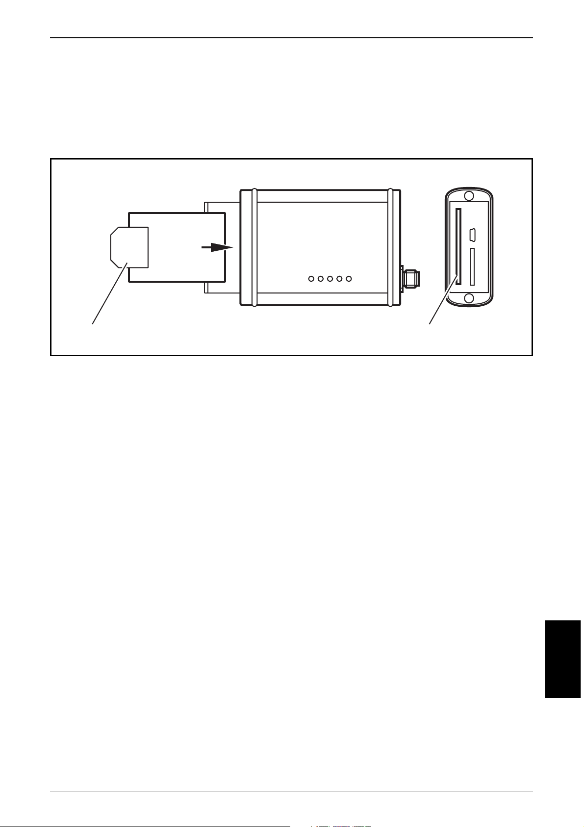
PCMCIA-Karte (PC-Card)
Versehen Sie die PCMCIA-Karte vor dem Ersteinsatz mit einer Auszughilfe (z.B.
Selbstklebestreifen). Diese Auszughilfe erleichtert das Entnehmen der Karte.
Wird die Speicherkarte falsch eingeschoben, verhindert eine mechanische Sperre
das Einschieben in die geräteinterne Steckerleiste.
Karten-Konfiguration und -Strukturierung
Das Anlegen der Kartenstruktur erfolgt mit dem Softwaretool „CANmem Configurator“. Entnehmen Sie die Vorgehensweise bitte dem Programmhandbuch.
Speicherfunktionen
Gespeichert werden Datensätze (struct, record), bestehend aus 1-8 Komponen-
ten (Prozessdaten, Variablen) unterschiedlicher Datentypen.
Folgende Datentypen sind möglich:
BYTE (u8), WORD (u16), INT (s16), DWORD (u32), DINT (s32), REAL (float 32).
Diese Datensätze werden entsprechend einer parametrierbaren Betriebsart in einer Datei abgelegt bzw. aus einer Datei gelesen. Bis zu 8 Dateien können angelegt werden. Es wird jeweils ein Datensatz angesprochen. Die Komponenten dieses aktuellen Datensatzes sind über das Objektverzeichnis zugänglich. Der aktuelle Datensatz wird über eine Adresse ausgewählt.
Jedem Datensatz wird in dem Gerät ein Eintrag für Datum/Uhrzeit und ein Eintrag mit dem Änderungsstatus der einzelnen Komponenten zugeordnet.
Das Speichern von Prozessdaten kann über PDOs oder SDO erfolgen. Das Lesen
von Datensätzen erfolgt ausschließlich per SDO.
Der adressierte (aktuelle) Datensatz steht jeweils im Objektverzeichnis (Idx 5000 +
Offset). Der Zugriff erfolgt per SDO oder PDO.
DEUTSCH
CANMEM CR3101
9
PCMCIA-SlotAuszughilfe
PC-Card
Page 10

Betriebsarten
Vorzugsweise erfolgt die Betriebsartenwahl mit dem Tool „CANmem Configurator“ oder über IEC-Funktionen des R360 Steuerungsprogramms. Alternativ kann
die Wahl auch durch SDO-Write mit einem beliebigen CANopen-Master erfolgen.
■ Direktes Schreiben/Speichern (Idx 3x03, Wert 0x01, Default):
Auf jede Komponente eines Datensatzes in einer Datei kann einzeln zugegegriffen werden. Im Datum/Zeitfeld wird die Zeit des letzten schreibenden Zugriffes
auf eine Komponente des Datensatzes abgelegt.
Die Adresse des Datensatzes (Zeilen-Nr.) muss vor jedem Zugriff vom Nutzer eingetragen werden.
■ Zyklisches Schreiben; (Idx 3x03, Wert 0x02):
In parametrierbaren Zeitintervallen (Cycletime 10 ms...24 h) wird die Adresse des
Datensatzes automatisch incrementiert. Im Datum/Zeitfeld wird dieser Zeitpunkt
abgelegt. Die zu diesem Zeitpunkt zuletzt übertragenen Werte für die einzelne
Komponente des Datensatzes werden gespeichert.
Die jeweils aktuelle Adresse des Datensatzes steht im Objektverzeichnis. Im Ringmodus wird beim Erreichen der Dateigrenze die aktuelle Adresse wieder zu Nullgesetzt, d.h. der erste Eintrag wird überschrieben. Im Linearmodus werden alle
weiteren Einträge verworfen. In jedem Modus wird beim Erreichen der Dateigrenze eine Fehlermeldung abgesetzt.
■ Autoincrement Schreiben; (Idx 3x03, Wert 0x03)
Diese Betriebsart ist für die meisten Anwendungen zu empfehlen. Sobald ein zuvor konfigurierter Identifier auf dem Bus sendet, werden die Komponenten (Daten) automatisch geschrieben.
Wie unter „Cycletime“ (10 ms...24 h) eingestellt, wird während des Schreibens
auf eine Komponente ein Zeitfenster gestartet. Nach dieser Zeit wird die Adresse
des Datensatzes automatisch incrementiert. Alle schreibenden Zugriffe innerhalb
dieses Zeitraumes gehen in den gleichen Datensatz.
Die Betriebsart ermöglicht ein minimals Zeitfenster von „0“. Bei dieser Einstellung
kann ca. jede Millisekunde ein Datensatz gespeichert werden.
Im Datum/Zeitfeld wird der Zeitpunkt nach Ablauf des Zeitfensters eingetragen.
Im Ringmodus wird beim Erreichen der Dateigrenze die aktuelle Adresse wieder
zu Null gesetzt, d.h. der 1. Eintrag wird überschrieben. Im Linearmodus werden
alle weiteren Einträge verworfen und die Betriebsart Direktes Lesen aktiviert. Beim
Erreichen der Dateigrenze wird in jedem Modus eine Fehlermeldung abgesetzt.
■ Direktes Lesen (Idx 3x03, Wert 0x10):
Um einen Datensatz zu lesen, muss die Adresse des Datensatzes eingetragen
werden. Die Komponenten des adressierten Datensatzes inkl. Zeit-/Datumsfeld
und Änderungsfeld stehen dann im Objekverzeichnis (Idx 5000 + Offset) und
werden per SDO gelesen.
CANMEM CR3101
10
Page 11

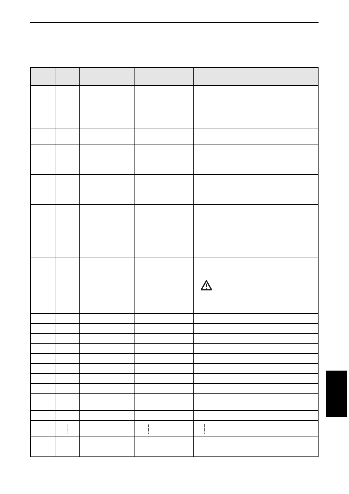
7. Parameter- und EMCY-Objekt-Übersicht
Parameterliste
DEUTSCH
CANMEM CR3101
11
Index Defaultwert Änderung Änderung
Parameter im Objekt- (werksseitig automatisch wirksam
verzeichnis eingestellt) gesichert
Herstellerspezifische Profile; Index 2000 bis 5FFF
Name (Kennung) 2000 "00000000000" ja sofort
der Speicherkarte
Status 2001 abhängig ja sofort
der Speicherkarte von Speicherkarte
- Karte gesteckt
- Kartentyp
- Schreibschutz
Speicheraufteilung 2002, 2003 0x00 ja sofort
(Größe Datei 1...8)
Datum/Uhrzeit 2010 – ja sofort
(Zeitstempel)
Node-ID 20F0, 20F1 0x20 (= 32) ja nach Reset
Baudrate 20F2, 20F3 0x03 (= 125 kBit/s) ja nach Reset
StartUp Mode 20F4 0x00 (
Pre-Operational Mode
) ja nach Reset
PDO Operating Mode 20F5 0x00 (
Logging Mode
) ja nach Reset
Datentypen, 30xx – ja sofort
Datenkonfiguration, bis
Betriebsarten, 37xx
Komponenten
Datensätze 5000 – ja sofort
bis
5700
Kommunikationsprofile; Index 1000 bis 1FFF
COB-ID Synch Objekt 1005 0x80 ja sofort
Communication Cycle 1006 0x00 (Off) ja nach Pre-Op
COB-ID Guarding 100E 0x700 + Node-ID ja sofort
COB-ID EMCY 1014 0x80 + Node-ID ja sofort
COB-ID Rec PDO 1 1400 0x00000200 + Node-ID ja sofort
COB-ID Rec PDO 2 1401 0x00000300 + Node-ID ja sofort
COB-ID Rec PDO 3 1402 0x00000400 + Node-ID ja sofort
COB-ID Rec PDO 4 1403 0x00000500 + Node-ID ja sofort
COB-ID Rec PDO 5 1404 0x80000100 + Node-ID ja sofort
COB-ID Rec PDO 6 1405 0x80000120 + Node-ID ja sofort
COB-ID Rec PDO 7 1406 0x80000140 + Node-ID ja sofort
COB-ID Rec PDO 8 1407 0x80000160 + Node-ID ja sofort
Page 12

EMCY-Objekte
Das Gerät unterstützt folgende EMCY-Objekte:
Datentest
Bei Dateien mit Vorgabewerten/Sollwerttabellen wird beim Erstellen der Dateien
am PC eine Check-Sum gebildet. Diese Check-Sum wird auf der Speicherkarte
abgelegt.
Bei jedem Einschalten der Versorgungsspannung oder beim Wechsel der Speicherkarte wird vom Gerät ebenfalls die Check-Sum über den Inhalt dieser Dateien
errechnet, und mit der abgelegten Check-Sum verglichen. Stimmen die beiden
Werte nicht überein, wird eine Fehlermeldung gesendet.
8. Betriebsanzeigen
In der Initialisierungsphase (ca. 5 Sek.) zeigen die LEDs noch keinen definierten Zustand an.
CANMEM CR3101
12
EMCY Code Error Reg Zusatz Code Beschreibung
0x5000 0x81 0x0000000000 "Device Hardware"
LowBatt
0x5001 0x81 0x000000000 "Device Hardware"
Es wurde versucht zu schreiben oder zu lesen,
obwohl keine Speicherkarte gesteckt war
0x5002 0x81 0x0000000001 "Device Hardware"
bis Bei einer Datei mit Sollwerten ist beim
0x0000000010 CRC-Check ein Fehler erkannt worden.
Die Nummer der Datei 1...8 wird im Zusatzcode mit übergeben.
0x6200 0x81 0x0000000001 "User Software"
bis Bei einer der Dateien wurde die Speicher0x0000000010 grenze überschritten.
Die Nummer der Datei 1...8 wird im Zusatzcode mit übergeben.
Status-LED Zustand Bedeutung
CARD ERROR (rot) EIN Speicherkarten Fehler
CARD ACCESS (grün) EIN Speicherkarten Zugriff aktiv
ON (grün) AUS Versorgungsspannung fehlt
EIN Versorgungsspannung ok
ERROR (rot) AUS keine Fehler
EIN CAN Bus off
blinkend CAN Busfehler / sonstige Fehler
CAN (grün) AUS Kein relevantes CAN-Objekt vorhanden
oder CAN nicht aktiv
oder Gerät nicht OPERATIONAL
EIN / blinkend Gerät OPERATIONAL und relevantes
CAN-Objekt erkannt
Page 13
9. Objektverzeichnis
Herstellerspezifische Profile; Index 2000 bis 5FFF (gem. CiA DS 301)
DEUTSCH
CANMEM CR3101
13
Index S-Idx Name Typ Default Beschreibung
2000 0x00 Name str11 "00000000000" Kennung (Name) der eingesteckten
der rw Speicherkarte.
Speicherkarte Wird vom Endanwender von der
Steuerungsseite aus über CANopen oder
von der PC-Seite aus eingegeben und ist
von beiden Seiten lesbar.
2001 0x00 Status der u8, ro 0x04 Anzahl der folgenden Einträge,
Speicherkarte die die Speicherkarte beschreiben
0x01 Speicherkarte u8, ro -- Gibt den Status zurück, ob sich eine
gesteckt Speicherkarte im CANmem befindet
0 = keine Karte im CANmem
1 = Karte im CANmem
0x02 Typ der u8, ro 0x00 Kennung des Speicherkartentyps
Speicherkarte 0 = SRAM-Karte
0x03 Write Protect u8, ro -- Gibt den Write Protect Status der
Status Speicherkarte im CANmem zurück
0 = nicht schreibgeschützt
1 = schreibgeschützt
0x04 Kapazität der u32, ro -- Kapazität der Speicherkarte in Byte
Speicherkarte (bei schreibgeschützten Karten kann die
Kapazität nicht ermittelt werden)
2002 0x00 Speicher- u8, ro 0x08 Mit den 8 folgenden Einträgen wird der
aufteilung Speicherplatz der Karte auf die einzelnen
Dateien verteilt.
Die Änderung eines Eintrags löscht
die gesamte Speicherkarte!
Eine Änderung wird nur dann gültig,
wenn in den Einträgen 2002 und 2003
der gleiche Wert steht!
0x01 Größe Datei 1 u32, rw 0x00 Größe der Datei 1 in Byte
0x02 Größe Datei 2 u32, rw 0x00 Größe der Datei 2 in Byte
0x03 Größe Datei 3 u32, rw 0x00 Größe der Datei 3 in Byte
0x04 Größe Datei 4 u32, rw 0x00 Größe der Datei 4 in Byte
0x05 Größe Datei 5 u32, rw 0x00 Größe der Datei 5 in Byte
0x06 Größe Datei 6 u32, rw 0x00 Größe der Datei 6 in Byte
0x07 Größe Datei 7 u32, rw 0x00 Größe der Datei 7 in Byte
0x08 Größe Datei 8 u32, rw 0x00 Größe der Datei 8 in Byte
2003 0x00 Speicher- u8, ro 0x08 wie Idx 2002
aufteilung (Einträge müssen übereinstimmen!)
0x01 Größe Datei 1 u32, rw 0x00 Größe der Datei 1 in Byte
0x08 Größe Datei 8 u32, rw 0x00 Größe der Datei 8 in Byte
Page 14

Herstellerspezifische Profile; Index 2000 bis 5FFF (gem. CiA DS 301)
CANMEM CR3101
14
Index S-Idx Name Typ Default Beschreibung
2010 0x00 Datum/Uhrzeit u8, rw 0x08 CANmem-Systemzeit für Zeitstempel.
Die aktuellen Werte werden vor der
Auslieferung des Geräte eingetragen.
Der Endanwender kann die Werte
ändern (z.B. beim Wechsel in eine
andere Zeitzone).
1 Millisekunden u16, rw -- Millisekunden
2 Sekunden u8, rw -- Sekunden
3 Minuten u8, rw -- Minuten
4 Stunden u8, rw -- Stunden
5 Tag-Monat u8, rw -- Tag-Monat
6 Monat u8, rw -- Monat
7 Jahr u8, rw -- Jahr
20F0 0x00 Einstellung u8, rw 0x20 Node-ID unter der CANmem im
20F1 Node-ID (= 32) CANopen Netz angesprochen wird
gültige Werte: 1...127
20F2 0x00 Einstellung u8, rw 0x03 Baudrate des CAN-Netzes
20F3 Baudrate 0 = 1000 kBaud
1 = 500 kBaud
2 = 250 kBaud
3 = 125 kBaud (Default)
4 = 100 kBaud
5 = 50 kBaud
6 = 20 kBaud
7 = 10 kBaud
20F4 0x00 CANopen u8, rw 0x00 CANmem Start-Modus
StartUp Mode 0 = Pre-Operational;
CANmem muss vom Master
initialisiert und in den Zustand
OPERATIONAL versetzt werden.
1 = Operational-Mode;
CANmem schaltet automatisch
in den OPERATIONAL-Modus.
20F5 0x00 PDO u8, rw 0x00 PDO Operating-Mode
Operating Mode 0 = Logging-Mode
1 = SD-/MMC-/PC-Card
PDO-Read Mode
(→ 10. Hinweise zur
Programmierung
→ PDO-Handling)
2 = Low-Level
SD-/MMC-/PC-Card
PDO-Read access
(wird nur von CANmem
Configurator-Software genutzt)
Bitte beachten:
In den Einträgen 20F0/20F1 sowie 20F2/20F3 muss stets der gleiche Wert eingetragen werden.
Änderungen sind wirksam nach Reset (Aus-/Einschalten)
Page 15

Herstellerspezifische Profile; Index 2000 bis 5FFF (gem. CiA DS 301)
DEUTSCH
CANMEM CR3101
15
Index S-Idx Name Typ Default Beschreibung
3000 0x00 Benennung u8, ro 0x02 Die folgenden 2 Einträge benennen
Datei 1 die Datei 1
0x01 Name str8 "Datei1" Der Name und die Erweiterung (S-Idx 2)
Datei 1 rw bilden zusammen den Bezeichner für
die Datei 1 (z.B. Öl_Temp.dat).
Der Bezeichner wird von Endanwender
entweder von der Steuerungseite oder
von der PC-Seite eingetragen und kann
von beiden Seiten gelesen werden.
0x02 Erweiterung str3 "dat" Datei-Erweiterung (Extention)
Datei 1 rw
3001 0x00 Relevante u16, rw 0x0000 Bitmap der relevanten Komponenten
Komponenten der in Datei 1 gespeicherten Datensätze.
in Datei 1 Jedes Bit repräsentiert eine Komponente.
3003 0x00 Konfiguration u8, ro 0x03 Die folgenden 3 Einträge beschreiben
Datei 1 die Betriebsart der Datei 1
0x01 Betriebsart u8, rw 0x01 Art des Zugriffs auf Datei 1
Datei 1 0x01 = Direktes Schreiben/Lesen
0x02 = Zyklisches Schreiben
0x03 = Autoincrement Schreiben
0x10 = Direktes Lesen
(→ 6. Speicherkarten → Betriebsarten)
0x02 Ring oder Linear u8, rw 0x00 Nur für zyklisches Schreiben und
Schreiben Autoincrement Schreiben relevant
Datei 1 0x00 = Linear, 0x55 = Ring
0x03 Zeitintervall u32, rw 0x01 Nur für zyklisches Schreiben und
Schreiben Autoincrement Schreiben relevant
Datei 1 (Zeitbasis = 10 ms)
3004 0x00 Aktueller u32, rw 0x00000000 Zeiger auf den nächsten zu
Datensatz schreibenden Datensatz
3005 0x00 Aktueller u32, rw
0x00000000 Zeiger auf den nächsten zu
Datensatz schreibenden Datensatz
3006 0x00 Anzahl u32, rw 0x00000000 Anzahl bisher beschriebener Datensätze
Datensätze = höchste bisher beschriebene Daten-
satzadresse (ist nur rücksetzbar mit
Eintrag 0x55)
3010 0x00 Komponente 1 u8, ro 0x02 Die folgenden 2 Einträge beschreiben
Datei 1 die Komponente 1 in Datei 1
0x01 Name str8 "Komp1" Bezeichnung der Komponente 1
Komponente 1 rw in Datei 1
0x02 Datentyp u16, rw 0x0006 Datentyp der Komponente 1 als Index
Komponente 1 des entsprechenden DEFTYPE-Obj. im
Datei 1 Objektverzeichnis
3011 0x... Komponente 2 Struktur wie Idx 3010 (Komponente 1)
(Idx 3012...3017)
3017 0x... Komponente 8 Struktur wie Idx 3010 (Komponente 1)
Page 16

Herstellerspezifische Profile; Index 2000 bis 5FFF (gem. CiA DS 301)
CANMEM CR3101
16
Index S-Idx Name Typ Default Beschreibung
3100 0x00 Benennung u8, ro 0x02 Die folgenden 2 Einträge benennen
Datei 2 die Datei 2
0x01 Name str8 "Datei2" Der Name und die Erweiterung (S-Idx 2)
Datei 2 rw bilden zusammen den Bezeichner für
die Datei 2 (z.B. Was_Temp.dat).
Der Bezeichner wird von Endanwender
entweder von der Steuerungseite oder
von der PC-Seite eingetragen und kann
von beiden Seiten gelesen werden.
0x02 Erweiterung str3 "dat" Datei-Erweiterung (Extention)
Datei 2 rw
3101 0x00 Relevante u16, rw 0x0000 Bitmap der relevanten Komponenten
Komponenten der in Datei 2 gespeicherten Datensätze.
in Datei 2 Jedes Bit repräsentiert eine Komponente.
3103 0x00 Konfiguration u8, ro 0x03 Die folgenden 3 Einträge beschreiben
Datei 2 die Betriebsart der Datei 2
0x01 Betriebsart u8, rw 0x01 Art des Zugriffs auf Datei 2
Datei 2 0x01 = Direktes Schreiben/Lesen
0x02 = Zyklisches Schreiben
0x03 = Autoincrement Schreiben
0x10 = Direktes Lesen
(→ 6. Speicherkarten → Betriebsarten)
0x02 Ring oder Linear u8, rw 0x00 Nur für zyklisches Schreiben und
Schreiben Autoincrement Schreiben relevant
Datei 2 0x00 = Linear, 0x55 = Ring
0x03 Zeitintervall u32, rw 0x01 Nur für zyklisches Schreiben und
Schreiben Autoincrement Schreiben relevant
Datei 2 (Zeitbasis = 10 ms)
3104 0x00 Aktueller u32, rw
0x00000000 Zeiger auf den nächsten zu
Datensatz schreibenden Datensatz
3105 0x00 Aktueller u32, rw
0x00000000 Zeiger auf den nächsten zu
Datensatz schreibenden Datensatz
3106 0x00 Anzahl u32, rw
0x00000000 Anzahl bisher beschriebener Datensätze
Datensätze = höchste bisher beschriebene Daten-
satzadresse (ist nur rücksetzbar mit
Eintrag 0x55)
3110 0x00 Komponente 1 u8, ro 0x02 Die folgenden 2 Einträge beschreiben
Datei 2 die Komponente 1 in Datei 2
0x01 Name str8 "Komp1" Bezeichnung der Komponente 1
Komponente 1 rw in Datei 2
0x02 Datentyp u16, rw 0x0006 Datentyp der Komponente 1 als Index
Komponente 1 des entsprechenden DEFTYPE-Obj. im
Datei 2 Objektverzeichnis
3111 0x... Komponente 2 Struktur wie Idx 3110 (Komponente 1)
(Idx 3112...3117)
3117 0x... Komponente 8 Struktur wie Idx 3110 ( Komponente 1)
Page 17

Herstellerspezifische Profile; Index 2000 bis 5FFF (gem. CiA DS 301)
DEUTSCH
CANMEM CR3101
17
Index S-Idx Name Typ Default Beschreibung
3200 0x00 Benennung u8, ro 0x02 Die folgenden 2 Einträge benennen
Datei 3 die Datei 3
0x01 Name str8 "Datei3" Der Name und die Erweiterung (S-Idx 2)
Datei 3 rw bilden zusammen den Bezeichner für
die Datei 3 (z.B. Öl_Druck.dat).
Der Bezeichner wird von Endanwender
entweder von der Steuerungseite oder
von der PC-Seite eingetragen und kann
von beiden Seiten gelesen werden.
0x02 Erweiterung str3 "dat" Datei-Erweiterung (Extention)
Datei 3 rw
3201 0x00 Relevante u16, rw 0x0000 Bitmap der relevanten Komponenten
Komponenten der in Datei 3 gespeicherten Datensätze.
in Datei 3 Jedes Bit repräsentiert eine Komponente.
3203 0x00 Konfiguration u8, ro 0x03 Die folgenden 3 Einträge beschreiben
Datei 3 die Betriebsart der Datei 3
0x01 Betriebsart u8, rw 0x01 Art des Zugriffs auf Datei 3
Datei 3 0x01 = Direktes Schreiben/Lesen
0x02 = Zyklisches Schreiben
0x03 = Autoincrement Schreiben
0x10 = Direktes Lesen
(→ 6. Speicherkarten → Betriebsarten)
0x02 Ring oder Linear u8, rw 0x00 Nur für zyklisches Schreiben und
Schreiben Autoincrement Schreiben relevant
Datei 3 0x00 = Linear, 0x55 = Ring
0x03 Zeitintervall u32, rw 0x01 Nur für zyklisches Schreiben und
Schreiben Autoincrement Schreiben relevant
Datei 3 (Zeitbasis = 10 ms)
3204 0x00 Aktueller u32, rw 0x00000000 Zeiger auf den nächsten zu
Datensatz schreibenden Datensatz
3205 0x00 Aktueller u32, rw
0x00000000 Zeiger auf den nächsten zu
Datensatz schreibenden Datensatz
3206 0x00 Anzahl u32, rw 0x00000000 Anzahl bisher beschriebener Datensätze
Datensätze = höchste bisher beschriebene Daten-
satzadresse (ist nur rücksetzbar mit
Eintrag 0x55)
3210 0x00 Komponente 1 u8, ro 0x02 Die folgenden 2 Einträge beschreiben
Datei 3 die Komponente 1 in Datei 3
0x01 Name str8 "Komp1" Bezeichnung der Komponente 1
Komponente 1 rw in Datei 3
0x02 Datentyp u16, rw 0x0006 Datentyp der Komponente 1 als Index
Komponente 1 des entsprechenden DEFTYPE-Obj. im
Datei 3 Objektverzeichnis
3211 0x... Komponente 2 Struktur wie Idx 3210 (Komponente 1)
(Idx 3112...3217)
3217 0x... Komponente 8 Struktur wie Idx 3210 (Komponente 1)
Page 18

Herstellerspezifische Profile; Index 2000 bis 5FFF (gem. CiA DS 301)
CANMEM CR3101
18
Index S-Idx Name Typ Default Beschreibung
33xx 0x... Benennung ... ... Die Struktur der Einträge ist identisch
Konfiguration mit den Einträgen für Datei 1...3
Betriebsart (siehe z.B. Idx 3000...3017)
Komponenten Zum Index wird lediglich der Wert
Datei 4 0x100 addiert.
(Idx 33xx...3717)
Datei 5...8
37xx 0x... Benennung ... ... Die Struktur der Einträge ist identisch
Konfiguration mit den Einträgen für Datei 1...3
Betriebsart (siehe z.B. Idx3000...3017)
Komponenten Zum Index wird lediglich der Wert
Datei 8 100hex addiert.
5000 0x00 Daten der u8, ro 0x16 Die folgenden Einträge beinhalten die
Komponenten Daten des jeweils aktuellen Datensatzes
1...8 von Datei 1.
Datei 1 (Wert von Idx 3004, 3005-1)
0x01 Millisekunden u16, ro Zeitstempel
0x02 Sekunden u8, rw "
0x03 Minuten u8, rw "
0x04 Stunden u8, rw "
0x05 Tag-Monat u8, rw "
0x06 Monat u8, rw "
0x07 Jahr u8, rw "
0x08 Komponente 1 u16, rw 0 Daten der Komponente 1
Datei 1 des aktuellen Datensatzes von Datei 1
(= Idx 3010, S-Idx 0x02)
0x09 Komponente 2 u16, rw 0 Daten der Komponente 2
Datei 1 des aktuellen Datensatzes von Datei 1
(= Idx 3011, S-Idx 0x02)
0x0A Komponente 3 u16, rw 0 Daten der Komponente 3
Datei 1 des aktuellen Datensatzes von Datei 1
(= Idx 3012, S-Idx 0x02)
(S-Idx 0x0B...0x0E)
0x0F Komponente 8 rw 0 Daten der Komponente 8
Datei 1 des aktuellen Datensatzes von Datei 1
(= Idx 3017, S-Idx 0x02)
5100 0x... Komp. Datei 2 Struktur wie Idx 5000
5200 0x... Komp. Datei 3 "
5300 0x... Komp. Datei 4 "
5400 0x... Komp. Datei 5 "
5500 0x... Komp. Datei 6 "
5600 0x... Komp. Datei 7 "
5700 0x... Komp. Datei 8 "
Page 19

DEUTSCH
CANMEM CR3101
19
Kommunikationsprofile; Index 1000 bis 1FFF (gem. CiA DS 301)
Index S-Idx Name Typ Default Beschreibung
1000 0x00 Device type u32, ro
0x00000000 Derzeit kein CANopen-Profil
für Speichermodule spezifiziert.
1001 0x00 Error register u8, ro 0x00 Bitcodiert gemäß Prof. 301;
unterstützt wird:
0b 0000 0000 kein Fehler
0b x00x 0001 generic error
0b x001 000x communication error
0b 100x 000x manufacturer specific
1002 0x00 State register u32, ro -- BitMap mit Flags für Card gesteckt,
Write Protection und Low Battery.
Bit-0 Card gesteckt
0 = keine Card im CANmem
1 = Card im CANmem
Bit-1 Write Protection
0 = Write Protection
1 = No Write Protection
Bit-2 Low Battery
0 = Low Battery
1 = Battery is ok
1003 0x00 Pre-defined u8, ro 0x02 Es wird eine Fehlerliste mit 4 Einträgen
errorfield unterstützt.
0x01-4 Error history u32, ro 0x00 Aufgetretener Fehler;
codiert entsprechend EMCY Liste;
der zuletzt aufgetretene Fehler steht
jeweils in Sub-Index 1
1005 0x00 COB-ID u32, ro 0x80000080 - CANmem erwartet Synch Meldung
Synch objekt (Bit 31 = 1)
- CANcom generiert keine Synch
Meldung (Bit 30 = 0)
- 11 Bit Identifier System (Bit 29 = 0)
- Identifier der Synch Meldung
(Bit 0...10)
1006 0x00 Communication. u32, ro
0x00000000 max. Zeit zwischen 2 Synch. Objekten
Cycle in µSek.; Nutzauflösung = 1 mSek.
1008 0x00 Device name str, ro CR3101 Gerätebezeichnung
1009 0x00 HW Version str, ro HV x.x Hardwareversion
100A 0x00 SW Version str, ro SV x.x Softwareversion
100B 0x00 Node-ID u32, ro -- nur zur Abfrage
100C 0x00 Guard time u16, ro 0x0000 Zeit in ms
Das Modul erwartet innerhalb dieser Zeit
ein "node guarding" des Netz-Masters.
Wird hier der Wert 0 eingetragen, wird
diese Funktion nicht unterstützt.
100D 0x00 Life time factor u8, ro 0x00 Wenn für "guard time" x "life time"
kein "node guarding" empfangen wird,
generiert das Modul ein EMCY.
Das Produkt aus "guard time" x "life
time" muss in dem Bereich zwischen
0...65535 liegen.
Page 20

Kommunikationsprofile; Index 1000 bis 1FFF (gem. CiA DS 301)
CANMEM CR3101
20
Index S-Idx Name Typ Default Beschreibung
1010 0x00 Number of u8, ro 0x01 Anzahl der Optionen "Sichern"
save-options
0x01 Store u32, rw 0x02 Alle Parameter werden bei einer
parameters Änderung automatisch gesichert.
1011 0x00 Number of u8, ro 0x01 Anzahl der Optionen "Reset"
restore-options
0x01 Restore default u32, rw 0x01 Wird hier der String "load" eingetragen,
parameters werden die Parameter mit den werkseiti-
gen Voreinstellungen belegt und sind
nach dem nächsten Reset gültig.
1014 0x00 COB-ID u32, rw 0x40000080 - Modul reagiert nicht auf
EMCY +Node-ID fremde EMCY Mess. (Bit 31 = 0)
- Modul generiert EMCY Mess.
(Bit 30 = 1)
- 11 Bit ID (Bit 29 = 0)
- ID = 0x80 + Node ID
CAN-Identifier kann vom Benutzer
geändert werden.
1200 0x00 Server SDO u8, ro 0x02 Anzahl der Einträge
0x01 COB-ID u32, ro 0x600 + - SDO ist gültig (Bit 31 = 0)
Rec SDO Node ID - CAN-ID des Receive SDOs
0x02 COB-ID u32, ro 0x580 + - SDO ist gültig (Bit 31 = 0)
Trans SDO Node ID - CAN-ID des Transmit SDOs
1400 0x00 Rec PDO 1 u8, ro 0x02 Anzahl der Einträge Receive PDO 1
0x01 COB-ID u32, rw
0x00000200 - PDO ist gültig (Bit 31 = 0)
Rec PDO 1 + Node-ID - CAN-ID des 1. Rec PDOs
0x02 Trans Type u8, rw 0x01 0x00 = synch acyclic
Rec PDO 1 0x01...0xF0 = synch cyclic;
Ausgänge werden erst nach „n“
Synch Objekten aktualisiert
n = 0x01 (1)...0xF0 (240)
0xFC nicht implementiert
0xFD nicht implementiert
0xFE = asynch man. spec. event;
Ausgänge werden sofort aktualisiert
0xFF = asynch device profile event;
Ausgänge werden sofort aktualisiert
(CANmem fest auf asynchron codiert!)
1401 0x00 Rec PDO 2 u8, ro 0x02 Anzahl der Einträge Receive PDO 2
0x01 COB-ID u32, rw 0x00000300 - PDO ist gültig (Bit 31 = 0)
Rec PDO 2 + Node-ID - CAN-ID des 2. Rec PDOs
0x02 Trans Type u8, rw 0x01 (siehe oben, Idx 1400)
Rec PDO 2
Page 21

Kommunikationsprofile; Index 1000 bis 1FFF (gem. CiA DS 301)
DEUTSCH
CANMEM CR3101
21
Index S-Idx Name Typ Default Beschreibung
1402 0x00 Rec PDO 3 u8, ro 0x02 Anzahl der Einträge Receive PDO 3
0x01 COB-ID u32, rw 0x00000400 - PDO ist gültig (Bit 31 = 0)
Rec PDO 3 + Node-ID - CAN-ID des 3. Rec PDOs
0x02 Trans Type u8, rw 0x01 0x00 = synch acyclic
Rec PDO 3 0x01...0xF0 = synch cyclic;
Ausgänge werden erst nach „n“
Synch Objekten aktualisiert
n = 0x01 (1)...0xF0 (240)
0xFC nicht implementiert
0xFD nicht implementiert
0xFE = asynch man. spec. event;
Ausgänge werden sofort aktualisiert
0xFF = asynch device profile event;
Ausgänge werden sofort aktualisiert
(CANmem fest auf asynchron codiert!)
1403 0x00 Rec PDO 4 u8, ro 0x02 Anzahl der Einträge Receive PDO 4
0x01 COB-ID u32, rw
0x00000500 - PDO ist gültig (Bit 31 = 0)
Rec PDO 4 + Node-ID - CAN-ID des 4. Rec PDOs
0x02 Trans Type u8, rw 0x01 (siehe oben, Idx 1402)
Rec PDO 4
1404 0x00 Rec PDO 5 u8, ro 0x02 Anzahl der Einträge Receive PDO 5
0x01 COB-ID u32, rw
0x80000100 - PDO ist gültig (Bit 31 = 0)
Rec PDO 5 + Node-ID - CAN-ID des 5. Rec PDOs
0x02 Trans Type u8, rw 0x01 (siehe oben, Idx 1402)
Rec PDO 5
1405 0x00 Rec PDO 6 u8, ro 0x02 Anzahl der Einträge Receive PDO 6
0x01 COB-ID u32, rw
0x80000120 - PDO ist gültig (Bit 31 = 0)
Rec PDO 6 + Node-ID - CAN-ID des 6. Rec PDOs
0x02 Trans Type u8, rw 0x01 (siehe oben, Idx 1402)
Rec PDO 6
1406 0x00 Rec PDO 7 u8, ro 0x02 Anzahl der Einträge Receive PDO 7
0x01 COB-ID u32, rw
0x80000140 - PDO ist gültig (Bit 31 = 0)
Rec PDO 7 + Node-ID - CAN-ID des 7. Rec PDOs
0x02 Trans Type u8, rw 0x01 (siehe oben, Idx 1402)
Rec PDO 7
1407 0x00 Rec PDO 8 u8, ro 0x02 Anzahl der Einträge Receive PDO 8
0x01 COB-ID u32, rw
0x80000160 - PDO ist gültig (Bit 31 = 0)
Rec PDO 8 + Node-ID - CAN-ID des 8. Rec PDOs
0x02 Trans Type u8, rw 0x01 (siehe oben, Idx 1402)
Rec PDO 8
Page 22

10. Hinweise zur Programmierung
Allgemeines
CANmem kann wahlweise als CANopen- oder als CAN-Layer 2 Gerät genutzt
werden. Im CAN-Layer 2 Modus wird kein CANopen-Master benötigt (CANmem
schaltet automatisch in den „OPERATIONAL“-Mode).
Wird CANmem als CANopen-Slave eingesetzt, muss es mit den CANopen-Startfunktionen „COP_MSTR_BOOTUP“ und „COP_MSTR_MAIN“ vom R 360-Master
initialisiert und in den Zustand „OPERATIONAL“ versetzt werden.
Sobald ein eingestellter Identifier auf dem Bus sendet, blinken die Status-LEDs
„CAN“ und „Card-Access“. Das Gerät zeichnet auf.
Beachten Sie, dass der Aufbau der CAN-Daten in der Applikation bzw. in
der Steuerung identisch mit der Kartenstruktur sein muss.
Wollen Sie beispielsweise einen Datensatz mit 4 Komponenten vom Typ Unsigned
16 speichern, muss das CAN-Objekt auf dem Bus bzw. im Steuerungsprogramm
folgenden Aufbau haben:
CAN-ID LSB/MSB 1. Wert (WORD), LSB/MSB 2. Wert (WORD),
LSB/MSB 3. Wert (WORD), LSB/MSB 4. Wert (WORD)
Programmier-Funktionen
Zur Einbindung des Moduls in das Applikationsprogramm hält ifm mehrere IECFunktionsbausteine bereit. Diese Funktionbausteine befinden sich in der Bibliothek „CANmem_x.lib“ der ifm-Programmiersoftware CoDeSys.
Informationen zu dieser Library entnehmen Sie bitte den Beispielprogrammen
und den Bibliotheksbeschreibungen unter CoDeSys.
Werden keine Konfigurationsdaten an CANmem übertragen, arbeitet das Gerät
mit den werkseitigen Default-Einstellungen.
Vor der Inbetriebnahme ist gegebenenfalls die werkseitige Node-ID des CANmems zu ändern und die Baudrate von Master und Modul auf Gleichheit zu prü-
fen bzw. einzustellen. Defaultwerte: Node-ID = 0x20 (= 32)
Baudrate = 0x03 (= 125 kBit/s)
Daten der Speicherkarte per PDO lesen
Über einen PDO-Mode kann das Lesen der Daten auch von einer Steuerung aus
erfolgen. In Verbindung mit ifm R360-Steuerungen steht für diese Betriebsart eine IEC-Bibliothek zur Verfügung (CANmem_x.lib).
Wird keine Bibliothek eingesetzt, müssen im Objektverzeichnis 20F5 (s. Seite 14)
die beschriebenen Einträge vorgenommen werden.
Das PDO-Handling muss dann, wie nachfolgend dargestellt, im Anwenderprogramm berücksichtigt werden.
CANMEM CR3101
22
i
Page 23

PDO-Handling in PDO-Operating Mode (Idx 20F5 = 1)
■ Rx-PDO 1 (Request)
■ Tx-PDO 1 (Answer), Requested Dataset part = 0 (values)
■ Tx-PDO 1 (Answer), Requested Dataset part = 1 (timestamp)
DEUTSCH
CANMEM CR3101
23
Datenbyte Inhalt Bemerkung
0 File Number (0...7)
1 Dataset pointer (LSB)
2 Dataset pointer
3 Dataset pointer
4 Dataset pointer (MSB)
5 Requested part of dataset 0 = values, 1 = timestamp
6 — nicht benötigt
7 — nicht benötigt
Datenbyte Inhalt Bemerkung
0..7 Dataset-Data 0...7
Datenbyte Inhalt Bemerkung
0 Millisekunden (MSB)
1 Millisekunden (LSB)
2 Sekunden
3 Minuten
4 Stunde
5 Tag-Monat
6 Monat
7 Jahr
Page 24

11. Wartung, Instandsetzung und Entsorgung
Da innerhalb des Datenspeichers keine vom Anwender zu wartenden Bauteile
enthalten sind, darf das Gehäuse nicht geöffnet werden. Die Instandsetzung des
Datenspeichers darf nur durch den Hersteller durchgeführt werden.
Die Entsorgung muss gemäß der nationalen Umweltvorschriften erfolgen.
12. Konformitätserklärung
Das CE-Zeichen wird angebracht auf Basis der EMV-Richtlinie 89/336/EWG, der
Richtlinie zur CE-Kennzeichnung 93/68/EWG sowie dem Gesetz über die elektromagnetische Verträglichkeit von Geräten (EMVG) vom 18. September 1998.
Herangezogene Normen:
Fachgrundnormen: EN 61000-6-4: 2001
EN 61000-6-1: 2001
Störaussendungen: Störfeldstärkenmessung nach EN 55022 Klasse A
Störfestigkeit: gegen schnelle Störgrößen (Burst) nach EN 61000-4-4
Entladung stat. Elektrizität nach EN 61000-4-2
Induzierte Störgößen nach EN 61000-4-6
Elektromagnetische Felder nach EN 61000-4-3
Dies ist eine Einrichtung der Klasse A. Diese Einrichtung kann im Wohnbereich Funkstörungen verursachen; in diesem Fall kann vom Betreiber verlangt werden, angemessene Massnahmen durchzuführen und dafür aufzukommen.
CANMEM CR3101
24
Page 25

DEUTSCH
CANMEM CR3101
25
13. Begriffe und Abkürzungen
0b ... binärer Zahlenwert (zur Bitcodierung), z.B. 0b0001 0000
0x ... hexadezimaler Zahlenwert, z.B. 0x64 (= 100 dezimal)
Baudrate Übertragungsgeschwindigkeit (1 Baud = 1 Bit/sec.)
CAL CAN Application Layer
CAN basierendes Netzwerkprotkoll auf Applikationsebene
CAN Controller Area Network (Bussystem für den Einsatz im Mobilbereich)
CAN_H CAN-High; CAN-Anschluss/-Leitung mit dem hohen Spannungspegel
CAN_L CAN-Low; CAN-Anschluss/-Leitung mit dem niederen Spannungspegel
CANopen CAN basierendes Netzwerkprotokoll auf Applikationsebene mit einer offe-
nen Konfigurationsschnittstelle (Objektverzeichnis).
CiA "CAN in Automation e.V."
(Anwender- und Herstellerorganisation in Deutschland/Erlangen)
Definitions- und Kontrollorgan für CAN und CAN-basierende Netzwerkprotokolle
CiA DS Draft Standard (veröffentlichte CiA-Spezifikation, die in der Regel ein Jahr
nicht geändert und erweitert wurde)
CiA DSP Draft Standard Proposal (veröffentlichter CiA-Spezifikationsentwurf)
CiA WD Work Draft (CiA-intern zur Diskussion akzeptiertes Arbeitspapier)
CiA DS 301 Spezifikation zum CANopen Kommunikationsprofil;
beschreibt die grundlegenden Kommunikationsmechanismen zwischen den
Netzwerkteilnehmern, wie z.B die Übertragung von Prozessdaten in Echtzeit,
den Datenaustausch zwischen Geräten oder die Konfigurationsphase.
Entspr. der Applikation ergänzt mit den nachfolgenden CiA-Spezifikationen:
CiA DS 401 Geräteprofil für digitale und analoge E/A-Baugruppen
CiA DS 402 Geräteprofil für Antriebe
CiA DS 403 Geräteprofil für Bediengeräte
CiA DS 404 Geräteprofil für Messtechnik und Regler
CiA DS 405 Spezifikation zur Schnittstelle zu programmierbaren Systemen (IEC61131-3)
CiA DS 406 Geräteprofil für Drehgeber/Encoder
CiA DS 407 Applikationsprofil für den öffentlichen Nahverkehr
COB CANopen Communication Object (PDO, SDO, EMCY, ...)
COB-ID CANopen Identifier eines Communication Objects
Communication cycle Die zu überwachende Synchronisationszeit; max. Zeit zwischen 2 Sync-Ob-
jekten
EMCY Object Emergency Object (Alarmbotschaft; Gerät signalisiert einen Fehler)
Error Reg Error Register (Eintrag mit einer Fehlerkennung)
Guarding Error Knoten bzw. Netzwerkteilnehmer wurde bzw. wird nicht mehr gefunden
Guard-MASTER: Einer oder mehrere SLAVES melden sich nicht mehr.
Guard-SLAVE: Das Gerät (SLAVE) wird nicht mehr abgefragt.
Guard Time Innerhalb dieser Zeit erwartet der Netzwerkteilnehmer ein "Node Guarding"
des Netz-Masters
Heartbeat Parametrierbare zyklische Überwachung von Netzwerkteilnehmern unterein-
ander. Im Gegensatz zum „Node Guarding“ wird kein übergeordneter NMTMaster benötigt.
ID Identifier; kennzeichnet eine CAN-Nachricht. Der numerische Wert des ID
beinhaltet gleichzeitig eine Priorität bezüglich des Bus-Zugriffes.
ID 0 = höchste Priorität.
Identifier siehe ID
Idx Index; bildet zusammen mit dem S-Index die Adresse eines Eintrages im Ob-
jektverzeichnis
Life Time Factor Anzahl der Versuche bei fehlender Guarding Antwort
Monitoring Wird verwendet um die Fehlerklasse (Guarding-Überwachung, Synch-, etc.)
zu beschreiben.
NMT Netzwerk-Management
NMT-Master/-Slaves Der NMT-Master steuert die Betriebzustände der NMT-Slaves
Page 26

CANMEM CR3101
26
Node Guarding Parametrierbare zyklische Überwachung von Slave-Netzwerkteilnehmern
durch einen übergeordneten Master-Knoten, sowie die Überwachung dieses
Abfragemechanismus durch die Slave-Teilnehmer.
Node-ID Knotenpunkt-Identifier (Kennung eines Teilnehmers im CANopen Netz)
Objekt (auch OBJ) Oberbegriff für austauschbare Daten/Botschaften innerhalb des CANopen-
Netzwerks
Objektverzeichnis enthält alle CANopen-Kommunikationsparameter eines Gerätes, sowie gerä-
tespezifische Parameter und Daten.
Auf die einzelnen Einträge wird über den Index und S-Index zugegriffen.
Operational Betriebszustand eines CANopen Teilnehmers.
In diesem Modus können SDOs, NMT-Kommandos und PDOs übertragen
werden.
PDO Process Data Object;
im CANopen Netz zur Übertragung von Prozessdaten in Echtzeit, wie z.B.
Drehzahl eines Motors.
PDOs besitzen eine höhere Priorität als SDOs; im Gegensatz zu SDOs werden
sie unbestätigt übertragen. PDOs bestehen aus einer CAN-Nachricht mit
Identifier und bis zu 8 Byte Nutzdaten.
PDO Mapping Beschreibt die Applikationsdaten, die mit einem PDO übertragen werden.
Pre-Op Preoperational; Betriebszustand eines CANopen Teilnehmers.
Nach den Einschalten der Versorgungsspannung geht jeder Teilnehmer automatisch in diesen Zustand.
Im CANopen-Netz können in diesem Modus nur SDOs und NMT-Kommandos übertragen werden, jedoch keine Prozessdaten
Prepared (auch stopped) Betriebszustand eines CANopen Teilnehmers.
In diesem Modus werden nur NMT- Kommandos übertragen.
Rec PDO (Receive) Empfangs Process Data Object
(auch Rx PDO)
ro read only (unidirektional; nur Lesen)
rw read-write (bidirektional; Lesen-Schreiben)
Rx-Queue Empfangspuffer
s16 Datentyp signed 16 bit (mit Vorzeichen, 16 Bit-Format)
SDO Service Data Object;
Mit diesem Objekt wird gezielt auf das Objektverzeichnis eines Netzwerkteilnehmers zugegriffen (lesen/schreiben). Ein SDO kann aus mehreren CANNachrichten bestehen. Die Übertragung der einzelnen Nachrichten wird von
dem angesprochenen Teilnehmer bestätigt.
Mit den SDOs lassen sich Geräte konfigurieren und parametrieren.
Server SDO Mechanismus und Parametersatz um das "eigene" Objektverzeichnis eines
Netzwerkteilnehmers anderen Teilnehmern (Clients) zugänglich zu machen.
S-Idx (auch SIdx) Subindex innerhalb d. Objektverzeichnisses eines CANopen fähigen Gerätes
Start Guarding Start der Knotenüberwachung
str Datentyp String (Variable für Zeichenketten, wie z.B. Text "load")
Sync Error Ausbleiben des Sync OBJ innerhalb der parametrierbaren Synchronisations-
zeit
Sync OBJ Synchronisationsobjekt zur netzwerkweit gleichzeitigen Aktualisierung bzw.
Übernahme der Prozessdaten der entsprechend parametrierten PDOs.
Sync Windows Zeitfenster in dem die synchronen PDOs übertragenen werden müssen.
Time Stamp Zeitstempel zum Abgleich evtl. vorhandener Uhren in Netzwerkteilehmern
Trans Type Art der Prozess-Datenübertragung; synchron, asynchron
Trans PDO (Transmit) Sende Process Data Object
(auch Tx PDO)
Trans SDO (Transmit) Sende Service Data Object
(auch Tx SDO)
Tx-Queue (Transmit) Sendepuffer
u8 (16, 32) Datentyp unsigned 8 (16, 32) bit (ohne Vorzeichen, 8 (16, 32) Bit-Format)
wo write only (nur schreiben)
Page 27

CANMEM CR3101
27
Page 28

Contents
1. Function and features . . . . . . . . . . . . . . . . . . . . . . . . . . . . . . . . page 29
2. CANopen communication overview . . . . . . . . . . . . . . . . . . . . . . page 30
3. Technical data . . . . . . . . . . . . . . . . . . . . . . . . . . . . . . . . . . . . . . page 31
4. Mounting . . . . . . . . . . . . . . . . . . . . . . . . . . . . . . . . . . . . . . . . . page 33
5. Electrical connection . . . . . . . . . . . . . . . . . . . . . . . . . . . . . . . . . page 33
6. Memory cards
SD/MMC card . . . . . . . . . . . . . . . . . . . . . . . . . . . . . . . . . . . . . . page 34
PCMCIA card . . . . . . . . . . . . . . . . . . . . . . . . . . . . . . . . . . . . . . page 34
7. Parameter and EMCY object overview. . . . . . . . . . . . . . . . . . . . . page 36
8. Operation indication (status LEDs). . . . . . . . . . . . . . . . . . . . . . . . page 38
9. Object directory
Manufacturer-specific profiles, index 2000 to 5FFF. . . . . . . . . . . . page 39
Communication profiles, index 1000 to 1FFF. . . . . . . . . . . . . . . . page 45
10. Notes on programming . . . . . . . . . . . . . . . . . . . . . . . . . . . . . . . page 48
11. Maintenance, repair and disposal . . . . . . . . . . . . . . . . . . . . . . . . page 50
12. Declaration of conformity. . . . . . . . . . . . . . . . . . . . . . . . . . . . . . page 50
13. Terms and abbreviations. . . . . . . . . . . . . . . . . . . . . . . . . . . . . . . page 51
CANMEM CR3101
28
Safety instructions
These instructions are part of the device. They contain text and illustrations for the correct handling of the module and must be
read before installation or use.
Adhere to the information in the documentation. Non-observance of the instructions, operation which is not in accordance with use as prescribed below,
incorrect installation or handling can affect the safety of people and equipment.
The device must be installed, connected and put into operation by a qualified
electrician.
Disconnect the device externally before handling it. Also disconnect any independently supplied output load circuits.
In case of malfunction of the device or uncertainties please contact the manufacturer. Tampering with the device can seriously affect the safety of people
and equipment. This is not permitted and leads to an exclusion of liability and
warranty.
Page 29

1. Function and features
Using CANmem process data of a running application can be stored on SD,
MMC or PCMCIA memory cards. Preset values already stored (plant parameters,
preset value tables, etc.) can be loaded to the controller.
The device can be directly used in the machine or the mobile equipment. The
CAN connection and the 10...30 V DC voltage supply are ensured via a 5-pole
M12 round plug.
Applications
■ Parameter setting of mobile machines and equipment
■ Buffer storage of remote diagnostic data
■ Storage of alarm and error messages (black box function)
■ Reading operational data from the machine in operation
■ Writing data blocks to and reading them from the RAM memory
Three software tools are available for CANmem:
• CANmem Configurator (configuration and structuring of the memory card),
• CANmem Downloader (updating and loading of operating systems),
• CANmem Reader (reading and conversion of the stored data).
These tools are described in the respective programming manual. A summary of
the manuals in PDF format can be downloaded from the Internet at "www.ifmelectronic.com".
➔ Data sheet direct ➔ CR3101 ➔ Additional Data.
www.ifm-electronic.com
ENGLISH
CANMEM CR3101
29
notebook
with SD/MMC or PCMCIA slot
or
transfer preset values
evaluate process data
load the operating system
transfer preset values
evaluate process data
USB
controller
sensors/actuators
CAN bus
SD/MMC card
or PCMCIA card
PC
Vorgabewerte übertragen
Prozeßdaten auswerten
Betriebssystem laden
oder Notebook mit
USB
SD-/PCMCIA-Slot
TOP
CARD ERROR
CARD ACCESS
ON
ERROR
CAN
CANmem
Vorgabewerte übertragen
Prozeßdaten auswerten
SD-/MMC- oder
PCMCIA-Card
CAN-Bus
Sensorik/Aktorik
Steuerung
Page 30

2. CAN communication overview
CANmem contains an object directory and supports the communication mechanisms in accordance with CiA DS 301 version 4.0. The parameters for the exchange of data (writing and reading) are set via entries in the object directory.
• 1 server SDO and 8 receive PDOs according to CiA DS 401 are available.
The default IDs are assigned according to the "predefined connection set".
The device supports no dynamic "PDO mapping".
• The COB IDs of the individual PDOs are configurable.
Modified PDOs (PDO linking) are stored non volatilely.
• The module expects a synch object.
The CAN identifier of the synch object is configurable. After a modification the
ID is automatically stored non volatilely.
• The module supports "node guarding".
The "guard time", "life time factor" and the CAN identifier of the guard object
are configurable and stored non volatilely.
• The module generates an emergency object.
The COB ID of the EMCY object is configurable.
• The module stores the last 4 errors.
The error code of the corresponding emergency object is stored.
• The module supports a reset function,
i.e. assignment of the default values* set at the factory to the parameters.
• The article no., HW and SW version are stored in the object directory and can
be read.
*) Default values set at the factory
→ 7. Parameter and EMCY object overview → List of parameters
CANMEM CR3101
30
Page 31

3. Technical data
ENGLISH
CANMEM CR3101
31
e.g. parameter setting of mobile machines and installations
storage of remote diagnostic data or alarm and error messages
aluminium
117.5 x 85 x 35 mm
with mounting bracket
(prepared mounting bores on the sides,
see mounting variants)
IP 65
-20 ... +80 °C (memory card depending on the type)
-40 ... +80 °C (memory card depending on the type)
250 g
10...30 V DC
supply via M12 plug
120 mA (at 24 V DC)
CAN interface 2.0 B, ISO 11898
M12 plug for operating voltage and CAN bus, 5 pins (type Lumberg)
CAN electrically separated
20 Kbits/s...1 Mbits/s (default setting 125 Kbits/s)
CANopen, CiA DS 301 version 3.0
hex 20 (= 32)
USB type mini B (female)
(for PC communication, configuration and firmware update)
Secure Digital (SD) or Multi Media Card (MMC)
for SRAM PC card type I up to 16 Mbytes (preferably 1 Mbyte)
enables exact data evaluation by time stamp,
e.g. for use as error memory or crash recorder (black box)
Memory card error (CARD ERROR)
Memory card access (CARD ACCESS)
Operating voltage (ON)
Communication fault (ERROR)
CAN mode (CAN)
\DATEN\100\DB-FORM—PZD/03/12/96
ifm electronic gmbh • Teichstraße 4 • 45 127 Essen 09.10.2006
CR3101
CANmem
Data memory and logger
for CANopen systems
Use of SD/MMC cards
and memory cards
to PCMCIA standard
Parameter setting
to IEC 61131
10 ... 30 V DC
We reserve the right to make technical alterations without prior notice. CR3101 / page 1
Application
Mechanical data
Housing
Dimensions (wx h x d)
Mounting
Protection
Operating temperature (device)
Storage temperature (device)
Weight
Electrical data
Operating voltage
Current consumption
Interfaces
CAN interface
Baud rate
Communication profile
Node ID (default)
USB interface
SD/MMC slot
PCMCIA slot
Other
Integrated real-time clock
Display (status LEDs)
1) CANopen interface
2) lid
3) USB interface
4) SD/MMC slot
5) PCMCIA slot
ERROR
CAN
117,5
ON
5 LED
130
35
CARD ERROR
85
1
CARD ACCESS
2
3
5
4
M12x1
Page 32

CANMEM CR3101
32
USB cable
type A – type mini B
length 1.8 m
Order no. EC2058
SRAM memory card (PCMCIA type 1) MByte
Order no. EC1020
CANmem
(configuration and evaluation software)
Order no. CP9012
The software can be obtained on request
or downloaded via the Internet (www.ifm-electronic.com) free of charge.
ifm electronic gmbh • Teichstraße 4 • 45 127 Essen 09.10.2006
We reserve the right to make technical alterations without prior notice. CR3101 / page 2
CARD ERROR
CARD ACCESS
ON
ERROR
CAN
CR3101
Mounting variants
Wiring CAN
(5 pole M12 plug)
Wiring USB
(5 pole type mini B)
Accessories
(to be ordered separately)
Software
Note
2
43
1
5
Description Pin Potential
Operating voltage 1 GND
2 10...30 V DC
CAN interface 3 CAN_GND
4 CAN_H
5 CAN_L
Pin Potential
1+ 5 V
2 Data –
3 Data +
4 ID (n.c.)
5 GND
Variante A Variante B
54321
Page 33

4. Mounting
Remove the 2 caps on the sides of the data memory to fix the mounting tabs.
The screws under the caps serve to fix the mounting tabs. Choose the suitable
fixing variant A or B depending on how much space is available (→ 3. Technical
data, mounting variants).
5. Electrical connection
To ensure protection against electrical interference the CANmem housing
must be connected to the vehicle ground. This is for example ensured when
the device is fixed to conductive vehicle parts using the supplied mounting tabs.
Since the CAN interface of the CANmem is electrically separated the potential "CAN_GND" of all CAN participants must be linked. Otherwise a safe
device function is not ensured or the CAN interface may be destroyed.
In addition, the "GND" potential of the operating voltage must be separately
connected.
The DC supply cables must not exceed 10 m.
Refer to the notes on classification → 12. Declaration of conformity
Wiring → 3. Technical data, wiring
USB interface
CANmem can be used as memory card reader via the USB interface. To do so,
the "CANmem Configurator" and the USB interface cable are needed (→ 3.
Technical data, accessories).
➔ Data sheet direct ➔ CR3101 ➔ Accessories
A firmware update is always carried out via USB with the "CANmem Downloader".
www.ifm-electronic.com
ENGLISH
CANMEM CR3101
33
Page 34

6. Memory card (not supplied with the device)
Adhere to the information of the memory card manufacturer.
Switch off CANmem when inserting or removing a memory card.
Opening the lid
The lid of the radio modem is equipped with a special spring hinge. To open the
lid slight pressure must be applied to the hinge.
When the unit is mounted e.g. a screw driver or a similar flat object can be used
to open the flap.
SD/MMC card
Insertion:
Before inserting SD cards unlock the mechanical write protection.
Insert the card carefully until it snaps into the SD/MMC slot.
Removal:
Press the card carefully into the unit until you hear the latching unlock and release.
CANMEM CR3101
34
Federscharnier
Verschlussklappe
Druckrichtung
Druckrichtung
direction
of pressure
direction
of pressure
spring hinge
lid
SD-/MMC-Karte
SD-/MMC-Slot
Lage
der Abschrägung
und Arretierung
SD/MMC slot
SD/MMC card
position
of the chamfer
and latching
Page 35

PCMCIA card (PC card)
Before using the PCMCIA card fit it with a pull-out aid (e.g. self-adhesive strip).
With this pull-out aid the card can be removed easily.
If the memory card is inserted incorrectly, insertion of the card into the device-internal plug-in strip is mechanically prevented.
Configuration and structuring of the card
The card is structured with the software tool "CANmem Configurator". How this
is done is described in the programming manual.
Storage functions
Data records (struct, record) consisting of 1-8 components (process data, vari-
ables) of different data types are stored.
The following data types are available:
BYTE (u8), WORD (u16), INT (s16), DWORD (u32), DINT (s32), REAL (float 32).
These data records are stored in a file or read from a file according to a selectable
operating mode. Up to 8 files can be created. One data record each is addressed.
The components of this current data record can be accessed via the object directory. The current data record is selected via an address.
In the device every data record is assigned an entry for date/time and an entry
with the modification status of the individual components.
Process data can be stored via PDOs or SDO. Data records are exclusively read via
SDO.
The addressed (current) data record is in the object directory (Idx 5000 + offset).
It is accessed via SDO or PDO.
ENGLISH
CANMEM CR3101
35
PCMCIA-SlotAuszughilfe
PC-Card
PCMCIA slotpull-out aid
Page 36

Operating modes
The operating modes are preferably selected using the tool "CANmem Configurator" or via the IEC functions of the R 360 controller program. As an alternative
the selection can be made with any CANopen master via SDO write.
■ Direct writing/storing (Idx 3x03, value 0x01, default):
It is possible to access every component of a data record in a file individually. In
the date/time field the time of the last write access to a component of the data
record is stored.
The address of the data record (line no.) must be entered by the user before each
access.
■ Cyclical writing (Idx 3x03, value 0x02):
In selectable time intervals (cycle time 10 ms...24 h) the address of the data
record is incremented automatically. This time is stored in the date/time field. The
last values transferred at this time for the individual components of the data
record are stored.
The current address of the data record is in the object directory. In the ring mode
the current address is again set to zero when the file limit has been reached, i.e.
the first entry is overwritten. In the linear mode all further entries are rejected. In
every mode an error message is given when the file limit has been reached.
■ Autoincrement writing (Idx 3x03, value 0x03)
This operating mode is recommended for most applications. As soon as an identifier configured before transmits data on the bus, the components (data) are written automatically.
As set in "Cycletime" (10 ms...24 h), a time window is started during the writing
to a component. When this time has elapsed the address of the data record is incremented automatically. All write accesses within this time are in the same data
record.
The operating mode enables a minimum time window of "0". With this setting a
data record can be stored approx. every millisecond.
After the cylce time has elapsed the time stamp is entered in the date/time field.
In the ring mode the current address is again set to zero when the file limit has
been reached, i.e. the first entry is overwritten. In the linear mode all other entries are rejected and the operating mode direct reading is activated. In every
mode an error message is given when the file limit has been reached.
■ Direct reading (Idx 3x03, value 0x10):
To read a data record, the address of the data record must be entered. The components of the addressed data record incl. time/date field and modification field
are then in the object directory (Idx 5000 + offset) and are read via SDO.
CANMEM CR3101
36
Page 37

7. Parameter and EMCY object overview
List of parameters
ENGLISH
CANMEM CR3101
37
Index in Default Change Change
Parameters the object value saved effective
directory (set at the factory) automatically
Manufacturer-specific profiles, index 2000 to 5FFF
Name (designation) 2000 "00000000000" yes at once
of the memory card
Status 2001 depending yes at once
of the memory card on the memory card
- Card inserted
- Card type
- Write protection
Memory allocation 2002, 2003 0x00 yes at once
(file size 1...8)
Date/Time 2010 – yes at once
(time stamp)
Node ID 20F0, 20F1 0x20 (= 32) yes after reset
Baud rate 20F2, 20F3 0x03 (= 125 Kbits/s) yes after reset
StartUp Mode 20F4 0x00 (
Pre-Operational Mode
) yes after reset
PDO Operating Mode 20F5 0x00 (
Logging Mode
) yes after reset
Data types, 30xx – yes at once
data configuration, bis
operating modes, 37xx
components
Data records 5000 – yes at once
bis
5700
Communication profiles; index 1000 to 1FFF
COB ID Synch Object 1005 0x80 yes at once
Communication Cycle 1006 0x00 (Off) yes after Pre-Op
COB ID Guarding 100E 0x700 + Node ID yes at once
COB ID EMCY 1014 0x80 + Node ID yes at once
COB ID Rec PDO 1 1400 0x00000200 + Node ID yes at once
COB ID Rec PDO 2 1401 0x00000300 + Node ID yes at once
COB ID Rec PDO 3 1402 0x00000400 + Node ID yes at once
COB ID Rec PDO 4 1403 0x00000500 + Node ID yes at once
COB ID Rec PDO 5 1404 0x80000100 + Node ID yes at once
COB ID Rec PDO 6 1405 0x80000120 + Node ID yes at once
COB ID Rec PDO 7 1406 0x80000140 + Node ID yes at once
COB ID Rec PDO 8 1407 0x80000160 + Node ID yes at once
Page 38

EMCY objects
The device supports the following EMCY objects:
Data test
For files with default values/preset value tables a checksum is formed when the
files are created on the PC. This checksum is stored on the memory card.
With every power on or when the memory card is exchanged, the device calculates the checksum of the contents of these files and compares it with the checksum stored. If the two values do not match, an error message is given.
8. Operation indication
In the initialisation phase (approx. 5 s) the LEDs indicate no defined state.
CANMEM CR3101
38
EMCY code Error reg Additional code Description
0x5000 0x81 0x0000000000 "Device hardware"
LowBatt
0x5001 0x81 0x000000000 "Device hardware"
An attempt was made to write or read
although no memory card was inserted.
0x5002 0x81 0x0000000001 "Device hardware"
bis For a file with preset values an error was
0x0000000010 found during a CRC check.
The number of the file 1...8 is transferred in
the additional code.
0x6200 0x81 0x0000000001 "User software"
bis For one of the files the memory limit
0x0000000010 was exceeded.
The number of the file 1...8 is transferred in
the additional code.
Status LED Status Description
CARD ERROR (red) ON Memory card error
CARD ACCESS (green) ON Memory card access active
ON (green) OFF Supply voltage missing
ON Supply voltage ok
ERROR (red) OFF no fault
ON CAN bus off
flashing CAN bus error / other error
CAN (green) OFF No relevant CAN object present
or CAN not active
or device not OPERATIONAL
ON / flashing Device OPERATIONAL and relevant
CAN object detected
Page 39

9. Object directory
Manufacturer-specific profiles, index 2000 to 5FFF (acc. to CiA DS 301)
ENGLISH
CANMEM CR3101
39
Index S-Idx Name Type Default Description
2000 0x00 Name str11 "00000000000" Designation (name) of the
of the rw inserted memory card.
memory card Entered by the end user from the
controller side via CANopen or from
the PC side and can be read from both
sides.
2001 0x00 Status of the u8, ro 0x04 Number of the following entries
memory card which describe the memory card
0x01 Memory card u8, ro -- Informs about the status whether
inserted a memory card is in the CANmem
0 = no card in the CANmem
1 = card in the CANmem
0x02 Type of u8, ro 0x00 Designation of the memory card type
memory card 0 = SRAM card
(At present other card types are not yet
supported)
0x03 Write protect u8, ro -- Informs about the write protect status
status of the memory card in the CANmem
0 = not write protected
1 = write protected
0x04 Capacity of the u32, ro -- Capacity of the memory card in bytes
memory card (for write protected cards the capacity
cannot be determined)
2002 0x00 Memory u8, ro 0x08 With the 8 following entries the
allocation storage space of the card is distributed
over the individual files.
The change of an entry erases the
whole memory card!
A change becomes valid only when the
entries 2002 and 2003 contain the
same value!
0x01 Size file 1 u32, rw 0x00 Size of the file 1 in bytes
0x02 Size file 2 u32, rw 0x00 Size of the file 2 in bytes
0x03 Size file 3 u32, rw 0x00 Size of the file 3 in bytes
0x04 Size file 4 u32, rw 0x00 Size of the file 4 in bytes
0x05 Size file 5 u32, rw 0x00 Size of the file 5 in bytes
0x06 Size file 6 u32, rw 0x00 Size of the file 6 in bytes
0x07 Size file 7 u32, rw 0x00 Size of the file 7 in bytes
0x08 Size file 8 u32, rw 0x00 Size of the file 8 in bytes
2003 0x00 Memory u8, ro 0x08 like Idx 2002
allocation (entries must match!)
0x01 Size file 1 u32, rw 0x00 Size of the file 1 in bytes
0x08 Size file 8 u32, rw 0x00 Size of the file 8 in bytes
Page 40

Manufacturer-specific profiles, index 2000 to 5FFF (acc. to CiA DS 301)
CANMEM CR3101
40
Index S-Idx Name Type Default Description
2010 0x00 Date/Time u8, rw 0x08 CANmem system time for time stamp.
The current values are entered before
delivery of the device.
The end user can change the values
(e.g. when changing to another time
zone).
1 Milliseconds u16, rw -- Milliseconds
2 Seconds u8, rw -- Seconds
3 Minutes u8, rw -- Minutes
4 Hours u8, rw -- Hours
5 Day month u8, rw -- Day month
6 Month u8, rw -- Month
7 Year u8, rw -- Year
20F0 0x00 Node ID u8, rw 0x20 Node ID used to address CANmem
20F1 setting (= 32) in the CANopen network
valid values: 1...127
20F2 0x00 Baud rate u8, rw 0x03 Baud rate of the CAN system
20F3 setting 0 = 1000 kBaud
1 = 500 kBaud
2 = 250 kBaud
3 = 125 kBaud (default)
4 = 100 kBaud
5 = 50 kBaud
6 = 20 kBaud
7 = 10 kBaud
20F4 0x00 CANopen u8, rw 0x00 CANmem StartUp Mode
StartUp mode 0 = Pre-operational mode
Device must be switched into
operational mode
1 = Operational mode
Device starts automatically in
operational mode
20F5 0x00 PDO u8, rw 0x00 PDO Operating Mode
Operating mode 0 = Logging Mode
1 = SD/MMC, PC card
PDO-Read Mode
(→ 10. Notes on programming
→ PDO handling)
2 = Low-Level
SD/MMC, PC card
PDO-Read access
(used only by CANmem
Configurator software)
Please note:
The entries 20F0/20F1 and 20F2/20F3 must always contain the same value.
Changes are effective after a reset (power off/on).
Page 41

Manufacturer-specific profiles, index 2000 to 5FFF (acc. to CiA DS 301)
ENGLISH
CANMEM CR3101
41
Index S-Idx Name Type Default Description
3000 0x00 Designation u8, ro 0x02 The following 2 entries name
file 1 the file 1
0x01 Name str8 "Datei1" The name and extension (S-Idx 2)
file 1 rw make up the designation for file 1
(e.g. oil_temp.dat).
The designation is entered by the end
user either from the controller side or
from the PC side and can be read from
both sides.
0x02 Extension str3 "dat" File extension
file 1 rw
3001 0x00 Relevant u16, rw 0x0000 Bitmap of the relevant components
components of the data records stored in file 1.
in file 1 Every bit represents a component.
3003 0x00 Configuration u8, ro 0x03 The following 3 entries describe
file 1 the operating mode of file 1
0x01 Operating mode u8, rw 0x01 Type of access to file 1
file 1 0x01 = direct writing/reading
0x02 = cyclical writing
0x03 = autoincrement writing
0x10 = direct reading
(→ 6. Memory card → Operating modes)
0x02 Ring or linear u8, rw 0x00 Only relevant for cyclical writing
writing and autoincrement writing
file 1 0x00 = linear, 0x55 = ring
0x03 Time interval u32, rw 0x01 Only relevant for cyclical writing
writing and autoincrement writing
file 1 (time base = 10 ms)
3004 0x00 Current u32, rw
0x00000000 Pointer to the next
data record data record to be written
3005 0x00 Current u32, rw 0x00000000 Pointer to the next
data record data record to be written
3006 0x00 Number u32, rw 0x00000000 Number of the data records written
of data records so far = highest data record address
written so far (can only be reset with
entry 0x55)
3010 0x00 Component 1 u8, ro 0x02 The following 2 entries describe
file 1 the component 1 in file 1
0x01 Name str8 "Komp1" Designation of the component 1
component 1 rw in file 1
0x02 Data type u16, rw 0x0006 Data type of the component 1 as index
component 1 of the corresponding DEFTYPE obj.
file 1 in the object directory
3011 0x... Component 2 Structure like Idx 3010 (component 1)
(Idx 3012...3017)
3017 0x... Component 8 Structure like Idx 3010 (component 1)
Page 42

Manufacturer-specific profiles, index 2000 to 5FFF (acc. to CiA DS 301)
CANMEM CR3101
42
Index S-Idx Name Type Default Description
3100 0x00 Designation u8, ro 0x02 The following 2 entries name
file 2 the file 2
0x01 Name str8 "Datei2" The name and extension (S-Idx 2)
file 2 rw make up the designation for file 2
(e.g. oil_temp.dat).
The designation is entered by the end
user either from the controller side or
from the PC side and can be read from
both sides.
0x02 Extension str3 "dat" File extension
file 2 rw
3101 0x00 Relevant u16, rw 0x0000 Bitmap of the relevant components
components of the data records stored in file 2.
in file 2 Every bit represents a component.
3103 0x00 Configuration u8, ro 0x03 The following 3 entries describe
file 2 the operating mode of file 2
0x01 Operating mode u8, rw 0x01 Type of access to file 2
file 2 0x01 = direct writing/reading
0x02 = cyclical writing
0x03 = autoincrement writing
0x10 = direct reading
(→ 6. Memory card → Operating modes)
0x02 Ring or linear u8, rw 0x00 Only relevant for cyclical writing
writing and autoincrement writing
file 2 0x00 = linear, 0x55 = ring
0x03 Time interval u32, rw 0x01 Only relevant for cyclical writing
writing and autoincrement writing
file 2 (time base = 10 ms)
3104 0x00 Current u32, rw 0x00000000 Pointer to the next
data record data record to be written
3105 0x00 Current u32, rw 0x00000000 Pointer to the next
data record data record to be written
3106 0x00 Number u32, rw
0x00000000 Number of the data records written
of data records so far = highest data record address
written so far (can only be reset with
entry 0x55)
3110 0x00 Component 1 u8, ro 0x02 The following 2 entries describe
file 2 the component 1 in file 2
0x01 Name str8 "Komp1" Designation of the component 1
component 1 rw in file 2
0x02 Data type u16, rw 0x0006 Data type of the component 1 as index
component 1 of the corresponding DEFTYPE obj.
file 2 in the object directory
3111 0x... Component 2 Structure like Idx 3110 (component 1)
(Idx 3112...3117)
3117 0x... Component 8 Structure like Idx 3110 (component 1)
Page 43

Manufacturer-specific profiles, index 2000 to 5FFF (acc. to CiA DS 301)
ENGLISH
CANMEM CR3101
43
Index S-Idx Name Type Default Description
3200 0x00 Designation u8, ro 0x02 The following 2 entries name
file 3 the file 3
0x01 Name str8 "Datei1" The name and extension (S-Idx 2)
file 3 rw make up the designation for file 3
(e.g. oil_temp.dat).
The designation is entered by the end
user either from the controller side or
from the PC side and can be read from
both sides.
0x02 Extension str3 "dat" File extension
file 3 rw
3201 0x00 Relevant u16, rw 0x0000 Bitmap of the relevant components
components of the data records stored in file 3.
in file 3 Every bit represents a component.
3203 0x00 Configuration u8, ro 0x03 The following 3 entries describe
file 3 the operating mode of file 3
0x01 Operating mode u8, rw 0x01 Type of access to file 3
file 3 0x01 = direct writing/reading
0x02 = cyclical writing
0x03 = autoincrement writing
0x10 = direct reading
(→ 6. Memory card → Operating modes)
0x02 Ring or linear u8, rw 0x00 Only relevant for cyclical writing
writing and autoincrement writing
file 3 0x00 = linear, 0x55 = ring
0x03 Time interval u32, rw 0x01 Only relevant for cyclical writing
writing and autoincrement writing
file 3 (time base = 10 ms)
3204 0x00 Current u32, rw
0x00000000 Pointer to the next
data record data record to be written
3205 0x00 Current u32, rw 0x00000000 Pointer to the next
data record data record to be written
3206 0x00 Number u32, rw 0x00000000 Number of the data records written
of data records so far = highest data record address
written so far (can only be reset with
entry 0x55)
3210 0x00 Component 1 u8, ro 0x02 The following 2 entries describe
file 3 the component 1 in file 3
0x01 Name str8 "Komp1" Designation of the component 1
component 1 rw in file 3
0x02 Data type u16, rw 0x0006 Data type of the component 1 as index
component 1 of the corresponding DEFTYPE obj.
file 3 in the object directory
3211 0x... Component 2 Structure like Idx 3210 (component 1)
(Idx 3212...3217)
3217 0x... Component 8 Structure like Idx 3210 (component 1)
Page 44

Manufacturer-specific profiles, index 2000 to 5FFF (acc. to CiA DS 301)
CANMEM CR3101
44
Index S-Idx Name Type Default Description
33xx 0x... Designation ... ... The structure of the entries is identical
configuration to the entries for files 1...3
operating mode (see for example Idx 3000...3017)
components Only the value 0x100 is added
file 4 to the index.
(Idx 33xx...3717)
Files 5...8
37xx 0x... Designation ... ... The structure of the entries is identical
configuration to the entries for files 1...3
operating mode (see for example Idx 3000...3017)
components Only the value 0x100 is added
file 8 to the index.
5000 0x00 Data of the u8, ro 0x16 The following entries contain
components the data of the current data record
1...8 of file 1.
file 1 (value of Idx 3004, 3005-1)
0x01 Milliseconds u16, ro Time stamp
0x02 Seconds u8, rw "
0x03 Minutes u8, rw "
0x04 Hours u8, rw "
0x05 Day month u8, rw "
0x06 Month u8, rw "
0x07 Year u8, rw "
0x08 Component 1 u16, rw 0 Data of the component 1
file 1 of the current data record of file 1
(= Idx 3010, S-Idx 0x02)
0x09 Component 2 u16, rw 0 Data of the component 2
file 1 of the current data record of file 1
(= Idx 3011, S-Idx 0x02)
0x0A Component 3 u16, rw 0 Data of the component 3
file 1 of the current data record of file 1
(= Idx 3012, S-Idx 0x02)
(S-Idx 0x0B...0x0E)
0x0F Component 8 rw 0 Data of the component 8
file 1 of the current data record of file 1
(= Idx 3017, S-Idx 0x02)
5100 0x... Comp. file 2 Structure like Idx 5000
5200 0x... Comp. file 3 "
5300 0x... Comp. file 4 "
5400 0x... Comp. file 5 "
5500 0x... Comp. file 6 "
5600 0x... Comp. file 7 "
5700 0x... Comp. file 8 "
Page 45

Communication profiles; index 1000 to 1FFF (acc. to CiA DS 301)
ENGLISH
CANMEM CR3101
45
Index S-Idx Name Type Default Description
1000 0x00 Device type u32, ro 0x00000000 At present no CANopen profile
for memory modules specified.
1001 0x00 Error register u8, ro 0x00 Bit coded according to prof. 301
Supported:
0b 0000 0000 no error
0b x00x 0001 generic error
0b x001 000x communication error
0b 100x 000x manufacturer specific
1002 0x00 State register u32, ro -- BitMap with flags for card inserted,
write protection and low battery.
Bit-0 card inserted
0 = no card in the CANmem
1 = card in the CANmem
Bit-1 write protected
0 = write protected
1 = not write protected
Bit-2 Low Battery
0 = Low Battery
1 = Battery is ok
1003 0x00 Pre-defined u8, ro 0x02 An error list with 4 entries is supported.
errorfield
0x01-4 Error history u32, ro 0x00 Error occurred,
coded according to EMCY list.
The last error is indicated in the
sub-index 1
1005 0x00 COB ID u32, ro
0x80000080 - CANmem expects synch message
Synch object (bit 31 = 1)
- CANmem generates no synch
message (bit 30 = 0)
- 11-bit identifier system (bit 29 = 0)
- Identifier of the synch message
(bit 0...10)
1006 0x00 Communication. u32, ro
0x00000000 Max. time between 2 synch. objects
Cycle in µs; useful resolution = 1 ms
1008 0x00 Device name str, ro CR3101 Device designation
1009 0x00 HW version str, ro HV x.x Hardware version
100A 0x00 SW version str, ro SV x.x Software version
100B 0x00 Node ID u32, ro -- read only
100C 0x00 Guard time u16, ro 0x0000 Time in ms
Within this time the module expects a
"node guarding" of the network master.
If the value 0 is entered here,
this function is not supported.
100D 0x00 Life time factor u8, ro 0x00 If no "node guarding" is received for
"guard time" x "life time", the module
generates an EMCY.
The product of "guard time" x "life
time" must be between 0 and 65535.
Page 46

Communication profiles; index 1000 to 1FFF (acc. to CiA DS 301)
CANMEM CR3101
46
Index S-Idx Name Type Default Description
1010 0x00 Number of u8, ro 0x01 Number of the "save options"
save options
0x01 Store u32, rw 0x02 All parameters are automatically
parameters saved after a change.
1011 0x00 Number of u8, ro 0x01 Number of the "reset" options
restore options
0x01 Restore default u32, rw 0x01 If the string "load" is entered here,
parameters the default parameters set at the
factory are restored and valid after the
next reset.
1014 0x00 COB ID u32, rw
0x40000080 - The module does not react to EMCY
EMCY +Node ID mess. of other devices (bit 31 = 0)
- The module generates EMCY mess.
(bit 30 = 1)
- 11 bit ID (bit 29 = 0)
- ID = 0x80 + Node ID
CAN identifier can be changed
by the user.
1200 0x00 Server SDO u8, ro 0x02 Number of the entries
0x01 COB ID u32, ro 0x600 + - SDO is valid (bit 31 = 0)
Rec SDO Node ID - CAN ID of the Receive SDO
0x02 COB ID u32, ro 0x580 + - SDO is valid (bit 31 = 0)
Trans SDO Node ID - CAN-ID of the Transmit SDO
1400 0x00 Rec PDO 1 u8, ro 0x02 Number of the entries Receive PDO 1
0x01 COB ID u32, rw 0x00000200 - PDO is valid (bit 31 = 0)
Rec PDO 1 + Node ID - CAN ID of the 1st Rec PDO
0x02 Trans Type u8, rw 0x01 0x00 = synch acyclic
Rec PDO 1 0x01...0xF0 = synch cyclic;
Outputs are only updated after "n"
synch objects
n = 0x01 (1)...0xF0 (240)
0xFC not implemented
0xFD not implemented
0xFE = asynch man. spec. event;
Outputs are updated immediately
0xFF = asynch device profile event;
Outputs are updated immediately
(CANmem permanently coded to
asynchronous!)
1401 0x00 Rec PDO 2 u8, ro 0x02 Number of the entries Receive PDO 2
0x01 COB ID u32, rw 0x00000300 - PDO is valid (bit 31 = 0)
Rec PDO 2 + Node ID - CAN ID of the 2nd Rec PDO
0x02 Trans Type u8, rw 0x01 (see above, Idx 1400)
Rec PDO 2
Page 47

Communication profiles; index 1000 to 1FFF (acc. to CiA DS 301)
ENGLISH
CANMEM CR3101
47
Index S-Idx Name Typ Default Beschreibung
1402 0x00 Rec PDO 3 u8, ro 0x02 Number of the entries Receive PDO 3
0x01 COB ID u32, rw
0x00000400 - PDO is valid (bit 31 = 0)
Rec PDO 3 + Node ID - CAN ID of the 3rd Rec PDO
0x02 Trans Type u8, rw 0x01 0x00 = synch acyclic
Rec PDO 3 0x01...0xF0 = synch cyclic;
Outputs are only updated after "n"
synch objects
n = 0x01 (1)...0xF0 (240)
0xFC not implemented
0xFD not implemented
0xFE = asynch man. spec. event;
Outputs are updated immediately
0xFF = asynch device profile event;
Outputs are updated immediately
(CANmem permanently coded to
asynchronous!)
1403 0x00 Rec PDO 4 u8, ro 0x02 Number of the entries Receive PDO 4
0x01 COB ID u32, rw 0x00000500 - PDO is valid (bit 31 = 0)
Rec PDO 4 + Node ID - CAN ID of the 4th Rec PDO
0x02 Trans Type u8, rw 0x01 (see above, Idx 1402)
Rec PDO 4
1404 0x00 Rec PDO 5 u8, ro 0x02 Number of the entries Receive PDO 5
0x01 COB ID u32, rw
0x80000100 - PDO is valid (bit 31 = 0)
Rec PDO 5 + Node ID - CAN ID of the 5th Rec PDO
0x02 Trans Type u8, rw 0x01 (see above, Idx 1402)
Rec PDO 5
1405 0x00 Rec PDO 6 u8, ro 0x02 Number of the entries Receive PDO 6
0x01 COB ID u32, rw 0x80000120 - PDO is valid (bit 31 = 0)
Rec PDO 6 + Node ID - CAN ID of the 6th Rec PDO
0x02 Trans Type u8, rw 0x01 (see above, Idx 1402)
Rec PDO 6
1406 0x00 Rec PDO 7 u8, ro 0x02 Number of the entries Receive PDO 7
0x01 COB ID u32, rw
0x80000140 - PDO is valid (bit 31 = 0)
Rec PDO 7 + Node ID - CAN ID of the 7th Rec PDO
0x02 Trans Type u8, rw 0x01 (see above, Idx 1402)
Rec PDO 7
1407 0x00 Rec PDO 8 u8, ro 0x02 Number of the entries Receive PDO 8
0x01 COB ID u32, rw 0x80000160 - PDO is valid (bit 31 = 0)
Rec PDO 8 + Node ID - CAN ID of the 8th Rec PDO
0x02 Trans Type u8, rw 0x01 (see above, Idx 1402)
Rec PDO 8
Page 48

10. Notes on programming
General
CANmem can be used either as CANopen or CAN Layer 2 unit. In the CAN Layer
2 mode no CANopen master is required (CANmen automatically switches to the
"OPERATIONAL" mode).
If CANmem is used as CANopen slave, it must be initialised by the R360 master
using the CANopen start functions "COP_MSTR_BOOTUP" and
"COP_MSTR_MAIN" and set to the state "OPERATIONAL".
As soon as a set identifier transmits data on the bus, the status LEDs "CAN" and
"Card Access" flash. The device is recording.
Please note that the structure of the CAN data in the application or in the controller must be identical to the card structure.
To store a data record with 4 components of the type unsigned 16 for example,
the CAN object on the bus or in the controller program must have the following
structure:
CAN ID LSB/MSB 1st value (WORD), LSB/MSB 2nd value (WORD),
LSB/MSB 3rd value (WORD), LSB/MSB 4th value (WORD).
Programming functions
To integrate the data memory into the application program ifm provides several
IEC function blocks. These function blocks can be found in the library "CANmem_1.lib" of the ifm programming software CoDeSys.
Information concerning this library is given in the example programs and the library descriptions under CoDeSys.
If no configuration data are transferred to CANmem, the device uses the default
values set at the factory.
Before start-up change the CANmem node ID set at the factory, if necessary and
check the baud rate of the master and module. If the baud rates are not identical, set them accordingly. Default values: Node ID = 0x20 (= 32)
Baud rate = 0x03 (= 125 Kbits/s)
Reading memory card data via a PDO
Via a PDO mode the memory card data can also be read from a controller. When
using ifm R360 controllers an IEC library is available for this operating mode
(CANmem_x.lib).
If no library is used the specified entries must be made in the object directory
20F5 (see page 40).
In that case the PDO handling must be taken into account in the user program,
as shown in the following.
CANMEM CR3101
48
Page 49

PDO handling in PDO operating mode (Idx 20F5 = 1)
■ RxPDO 1 (request)
■ TxPDO 1 (answer), requested dataset part = 0 (values)
■ TxPDO 1 (answer), requested dataset part = 1 (timestamp)
ENGLISH
CANMEM CR3101
49
Data byte Contents Comment
0 File number (0...7)
1 Dataset pointer (LSB)
2 Dataset pointer
3 Dataset pointer
4 Dataset pointer (MSB)
5 Requested part of dataset 0 = values, 1 = timestamp
6 — not required
7 — not required
Data byte Contents Comment
0..7 Dataset data 0...7
Data byte Contents Comment
0 Milliseconds (MSB)
1 Milliseconds (LSB)
2 Seconds
3 Minutes
4 Hour
5 Day month
6 Month
7 Year
Page 50

11. Maintenance, repair and disposal
As no components to be maintained by the user are contained in the data memory, the housing must not be opened. The data memory can only be repaired by
the manufacturer.
The device must be disposed of in accordance with the national environmental
regulations.
12. Declaration of conformity
The CE mark is applied on the basis of the EMC Directive 89/336/EEC, the CE
Marking Directive 93/68/EEC and the Law on Electromagnetic Compatibility of
Equipment dated 18 September 1998.
Standards used:
Generic standards: EN 61000-6-4: 2001
EN 61000-6-1: 2001
Noise emission: measurement of the noise field strength to EN 55022 class A
Noise immunity: to fast interference (burst) to EN 61000-4-4
discharge of static electricity to EN 61000-4-2
induced interference to EN 61000-4-6
electromagnetic fields to EN 61000-4-3
This is a class A installation. It can cause radio interference in domestic
areas. In this case the operator is requested to take appropriate measures at
his own expense.
CANMEM CR3101
50
Page 51

ENGLISH
CANMEM CR3101
51
13. Terms and abbreviations
0b ... binary value (for bit coding), e.g. 0b0001 0000
0x ... hexadecimal value, e.g. 0x64 (= 100 decimal)
Baudrate transmission speed (1 baud = 1 bit/s)
CAL CAN Application Layer
CAN-based network protocol on application level
CAN Controller Area Network (bus system for use in mobile applications)
CAN_H CAN-High; CAN connection /cable with high voltage level
CAN_L CAN-Low; CAN connection /cable with low voltage level
CANopen CAN-based network protocol on application level with an open configura-
tion interface (object directory)
CiA "CAN in Automation e.V."
(user and manufacturer organisation in Germany /Erlangen)
Definition and control body for CAN and CAN-based network protocols
CiA DS Draft Standard (published CiA specification which usually has not been mo-
dified or supplemented for one year)
CiA DSP Draft Standard Proposal (published CiA specification draft)
CiA WD Work Draft (work draft accepted for discussion within CiA)
CiA DS 301 Specification for CANopen communication profile;
describes the basic communication between network participants, such as
the transfer of process data in real time, the exchange of data between
units or the configuration stage. Depending on the application this is completed by the following CiA specifications:
CiA DS 401 Device profile for digital and analog I/O modules
CiA DS 402 Device profile for drives
CiA DS 403 Device profile for HMI
CiA DS 404 Device profile for measurement and control technology
CiA DS 405 Specification for interfaces to programmable systems (IEC 1131)
CiA DS 406 Device profile for encoders
CiA DS 407 Application profile for local public transport
COB CANopen Communication Object (PDO, SDO EMCY, ...)
COB ID CANopen Identifier of a Communication Object
Communication cycle the synchronisation time to be monitored, max. time between 2 Sync ob-
jects
EMCY Object Emergency Object (alarm message, device indicates an error)
Error Reg Error Register (entry with an error code)
Guarding Error Node or network participant could or can no longer be found
Guard Master: one or several slaves no longer reply
Guard Slave: no polling of the slave
Guard Time During this time the network participant expects a "Node Guarding" of the
network master
Heartbeat Cyclic monitoring with parameter setting among network participants.
In contrast to "node guarding" no superior NMT master is required.
ID Identifier; identifies a CAN message. The numerical value of the ID also
contains a priority for the access to the bus system
ID 0 = top priority
Identifier see ID
Idx index; together with the S index it forms the address of an entry in the ob-
ject directory
Life Time Factor number of attempts in case of a missing Guarding reply
Monitoring is used to describe the error class (guarding monitoring, synch etc.)
NMT network management
NMT master/slaves The NMT master controls the operating states of the NMT slaves
Node Guarding adjustable cyclic monitoring of slave network participants by a higher ma-
ster node as well as the monitoring of this polling process by the slave participants
Page 52

CANMEM CR3101
52
Node ID node identifier (identification of a participant in the CANopen network)
Object (also OBJ) term for data/messages which can be exchanged in the CANopen network
Object directory contains all CANopen communication parameters of a device as well as de-
vice-specific parameters and data
Access to the individual entries is possible via the index and S index.
Operational Operating state of a CANopen participant
In this mode SDOs, NMT commands and PDOs can be transferred.
PDO Process Data Object;
in the CANopen network for transfer of process data in real time; such as
the speed of a motor
PDOs have a higher priority than SDOs; in contrast to the SDOs they are
transferred without confirmation. PDOs consist of a CAN message with
identifier and up to 8 bytes of user data.
PDO Mapping describes the application data transferred with a PDO.
Pre-Op Preoperational; operating state of a CANopen participant. After application
of the supply voltage each participant automatically goes into this state.
In the CANopen network only SDOs and NMT commands can be transferred in this mode but no process data.
Prepared (also stopped) operating state of a CANopen participant
In this mode only NMT commands are transferred.
Rec PDO Receive Process Data Object
(also Rx PDO)
ro read only (unidirectional)
rw read-write (bidirectional)
RX-Queue reception buffer
s16 data type signed 16 bit
SDO Service Data Object;
With this object direct access to the object directory of a network participant is possible (read/write). An SDO can consist of several CAN messages.
The transfer of the individual messages is confirmed by the addressed participant.
With the SDOs devices can be configured and parameters can be set.
Server SDO process and parameter set to make the object directory of a network parti-
cipant available to other participants (clients).
S-Idx (also Sldx) Subindex within the object directory of a CANopen device
Start Guarding start node guarding
str data type string (variable for strings such as text "load")
Sync Error missing Sync OBJ in the adjustable communication cycle
Sync object synchronisation object for simultaneous update in the complete network or
for accepting process data of the respective parameterised PDOs.
Sync Windows time during which the synchronous PDOs have to be transferred
Time Stamp time stamp to align existing clocks in network participants
Trans Type type of process data transmission; synchronous, asynchronous
Trans PDO transmit process data object
(also Tx PDO)
Trans SDO transmit service data object
(also Tx SDO)
Tx Queue (transmit) transmission buffer
u8 (16, 32) data type unsigned 8 (16, 32) bits
wo write only
Page 53

Technische Änderungen behalten wir uns ohne vorherige Ankündigung vor. • We reserve the right to make technical alterations without prior notice. • Nous nous réservons le droit de modifier les données techniques sans préavis.
 Loading...