

IFM Electronic CR2532, CR2530 Installation Instructions Manual
Installation instructions
SmartController XL
CR2532
80003974 / 00 04 / 2014
UK

SmartController XL CR2532
2
Contents
1 Preliminary note � � � � � � � � � � � � � � � � � � � � � � � � � � � � � � � � � � � � � � � � � � � � � � � � � 4
1�1 Symbols used� � � � � � � � � � � � � � � � � � � � � � � � � � � � � � � � � � � � � � � � � � � � � � � 4
1�2 Warning signs used � � � � � � � � � � � � � � � � � � � � � � � � � � � � � � � � � � � � � � � � � � 4
2 Safety instructions � � � � � � � � � � � � � � � � � � � � � � � � � � � � � � � � � � � � � � � � � � � � � � � 5
2�1 General� � � � � � � � � � � � � � � � � � � � � � � � � � � � � � � � � � � � � � � � � � � � � � � � � � � � 5
2�2 Target group � � � � � � � � � � � � � � � � � � � � � � � � � � � � � � � � � � � � � � � � � � � � � � � � 5
2�3 Electrical connection � � � � � � � � � � � � � � � � � � � � � � � � � � � � � � � � � � � � � � � � � 5
2�4 Housing temperature � � � � � � � � � � � � � � � � � � � � � � � � � � � � � � � � � � � � � � � � � 5
2�5 Tampering with the device � � � � � � � � � � � � � � � � � � � � � � � � � � � � � � � � � � � � � 6
2�6 Electromagnetic compatibility� � � � � � � � � � � � � � � � � � � � � � � � � � � � � � � � � � � 6
2�7 Electrical welding on vehicles and plants � � � � � � � � � � � � � � � � � � � � � � � � � � 6
3 Functions and features � � � � � � � � � � � � � � � � � � � � � � � � � � � � � � � � � � � � � � � � � � � � 6
4 Installation� � � � � � � � � � � � � � � � � � � � � � � � � � � � � � � � � � � � � � � � � � � � � � � � � � � � � � 7
4�1 Fastening � � � � � � � � � � � � � � � � � � � � � � � � � � � � � � � � � � � � � � � � � � � � � � � � � � 7
4�2 Installation position� � � � � � � � � � � � � � � � � � � � � � � � � � � � � � � � � � � � � � � � � � � 7
4�3 Mounting surface � � � � � � � � � � � � � � � � � � � � � � � � � � � � � � � � � � � � � � � � � � � � 8
4�4 Heat dissipation � � � � � � � � � � � � � � � � � � � � � � � � � � � � � � � � � � � � � � � � � � � � � 8
5 Electrical connection� � � � � � � � � � � � � � � � � � � � � � � � � � � � � � � � � � � � � � � � � � � � � � 9
5�1 Wiring � � � � � � � � � � � � � � � � � � � � � � � � � � � � � � � � � � � � � � � � � � � � � � � � � � � � � 9
5�2 Ground connection � � � � � � � � � � � � � � � � � � � � � � � � � � � � � � � � � � � � � � � � � � � 9
5�3 Fuses � � � � � � � � � � � � � � � � � � � � � � � � � � � � � � � � � � � � � � � � � � � � � � � � � � � � 10
5�4 Laying the supply and signal cables� � � � � � � � � � � � � � � � � � � � � � � � � � � � � 10
5�5 Frequency and analogue inputs � � � � � � � � � � � � � � � � � � � � � � � � � � � � � � � � �11
5�6 Resistor inputs � � � � � � � � � � � � � � � � � � � � � � � � � � � � � � � � � � � � � � � � � � � � � �11
5�7 CAN wiring St/Ex side � � � � � � � � � � � � � � � � � � � � � � � � � � � � � � � � � � � � � � � 12
5�7�1 Point-to-point wiring � � � � � � � � � � � � � � � � � � � � � � � � � � � � � � � � � � � � � 12
5�7�2 Open CANopen network � � � � � � � � � � � � � � � � � � � � � � � � � � � � � � � � � 12
5�8 Connection technology� � � � � � � � � � � � � � � � � � � � � � � � � � � � � � � � � � � � � � � 12
6 Set-up � � � � � � � � � � � � � � � � � � � � � � � � � � � � � � � � � � � � � � � � � � � � � � � � � � � � � � � � 13
6�1 Programming � � � � � � � � � � � � � � � � � � � � � � � � � � � � � � � � � � � � � � � � � � � � � � 13
6�2 Required documentation � � � � � � � � � � � � � � � � � � � � � � � � � � � � � � � � � � � � � 13
7 Technical data� � � � � � � � � � � � � � � � � � � � � � � � � � � � � � � � � � � � � � � � � � � � � � � � � � 14
7�1 Mechanical and electric data � � � � � � � � � � � � � � � � � � � � � � � � � � � � � � � � � � 14
7�2 Test standards and regulations � � � � � � � � � � � � � � � � � � � � � � � � � � � � � � � � 16
7�3 St side / input characteristics � � � � � � � � � � � � � � � � � � � � � � � � � � � � � � � � � � 17
7�4 St side / output characteristics � � � � � � � � � � � � � � � � � � � � � � � � � � � � � � � � � 19
7�5 Ex side / input characteristics� � � � � � � � � � � � � � � � � � � � � � � � � � � � � � � � � � 21
7�6 Ex side / output characteristics� � � � � � � � � � � � � � � � � � � � � � � � � � � � � � � � � 23
7�7 St side / wiring � � � � � � � � � � � � � � � � � � � � � � � � � � � � � � � � � � � � � � � � � � � � � 25
7�8 Ex side / wiring � � � � � � � � � � � � � � � � � � � � � � � � � � � � � � � � � � � � � � � � � � � � � 26
8 Maintenance, repair and disposal� � � � � � � � � � � � � � � � � � � � � � � � � � � � � � � � � � � 27

UK
SmartController XL CR2532
3
This document is the original instructions�
Licences and trademarks
All trademarks and company names are subject to the copyright of the respective companies�
9 Approvals/standards � � � � � � � � � � � � � � � � � � � � � � � � � � � � � � � � � � � � � � � � � � � � � 27
SmartController XL CR2532
4
1 Preliminary note
This document applies to devices of the type "SmartController XL" (art� no�:
CR2532)�
These instructions are part of the device�
This document is intended for specialists� These specialists are people who are
qualified by their appropriate training and their experience to see risks and to
avoid possible hazards that may be caused during operation or maintenance of
the device� The document contains information about the correct handling of the
device�
Read this document before use to familiarise yourself with operating conditions,
installation and operation� Keep this document during the entire duration of use of
the device�
Adhere to the safety instructions�
1.1 Symbols used
► Instructions
> Reaction, result
[…] Designation of pushbuttons, buttons or indications
→ Cross-reference
Important note
Non-compliance can result in malfunction or interference�
Information
Supplementary note
1.2 Warning signs used
WARNING
Warning of serious personal injury�
Death or serious irreversible injuries may result�
CAUTION
Warning of personal injury�
Slight reversible injuries may result�
NOTE
Warning of damage to property�

UK
SmartController XL CR2532
5
2 Safety instructions
2.1 General
These instructions are part of the device� They contain texts and figures
concerning the correct handling of the device and must be read before installation
or use�
Observe the operating instructions� Non-observance of the instructions, operation
which is not in accordance with use as prescribed below, wrong installation or
incorrect handling can seriously affect the safety of operators and machinery�
2.2 Target group
These instructions are intended for authorised persons according to the EMC and
low-voltage directives� The device must only be installed, connected and put into
operation by a qualified electrician�
2.3 Electrical connection
Disconnect the device externally before handling it� If necessary, also disconnect
any independently supplied output load circuits�
If the device is not supplied by the mobile on-board system (12/24 V battery
operation), it must be ensured that the external voltage is generated and supplied
according to the criteria for safety extra-low voltage (SELV) as this voltage is
supplied without further measures to the connected controller, the sensors and the
actuators�
The wiring of all signals in connection with the SELV circuit of the device must also
comply with the SELV criteria (safety extra-low voltage, safe electrical isolation
from other electric circuits)�
If the supplied SELV voltage is externally grounded (SELV becomes PELV), the
responsibility lies with the user and the respective national installation regulations
must be complied with� All statements in this document refer to the device the
SELV voltage of which is not grounded�
The connection terminals may only be supplied with the signals indicated in the
technical data and/or on the device label and only the approved accessories of ifm
electronic gmbh may be connected�
2.4 Housing temperature
As described in the technical specifications below the device can be operated
in a wide ambient temperature range� Because of the additional internal heating
the housing walls can have high perceptible temperatures when touched in hot
environments�
SmartController XL CR2532
6
2.5 Tampering with the device
In case of malfunctions or uncertainties please contact the manufacturer�
Tampering with the device can seriously affect the safety of operators and
machinery� This is not permitted and leads to the exclusion of any liability and
warranty claims�
2.6 Electromagnetic compatibility
This is a class A product� It can cause radio interference in domestic areas� In this
case the operator is requested to take appropriate measures�
2.7 Electrical welding on vehicles and plants
Welding work on the chassis frame must only be carried out by qualified persons�
Remove and cover the plus and minus terminals of the batteries�
Disconnect all contacts of the controller from the on-board system prior to welding
on the vehicle or plant� Connect the earth terminal of the welding device directly to
the part to be welded�
Do not touch the controller or electric cables with the welding electrode or the
earth terminal of the welding device�
Protect the controller against weld slag�
3 Functions and features
The freely programmable controllers of the "SmartController XL" series are
rated for use under difficult conditions (e�g� extended temperature range, strong
vibration, intensive EMC interference)�
They are suited for direct installation in machines in mobile and robust
applications� Integrated hardware and software functions (operating system) offer
high protection for the machine�
The controllers can be used as CANopen master�
WARNING
The SmartController XL series is not approved for safety tasks in the field of
safety of persons�
WARNING
The user is responsible for the safe function of the application programs which he
created himself�
If necessary, he must additionally carry out an approval test by corresponding
supervisory and test organisations according to the national regulations�
UK
SmartController XL CR2532
7
4 Installation
4.1 Fastening
► Fix the controller to a flat surface using 4 M5 screws�
Screw material: steel or stainless steel
Tightening torque: 8 ±2 Nm
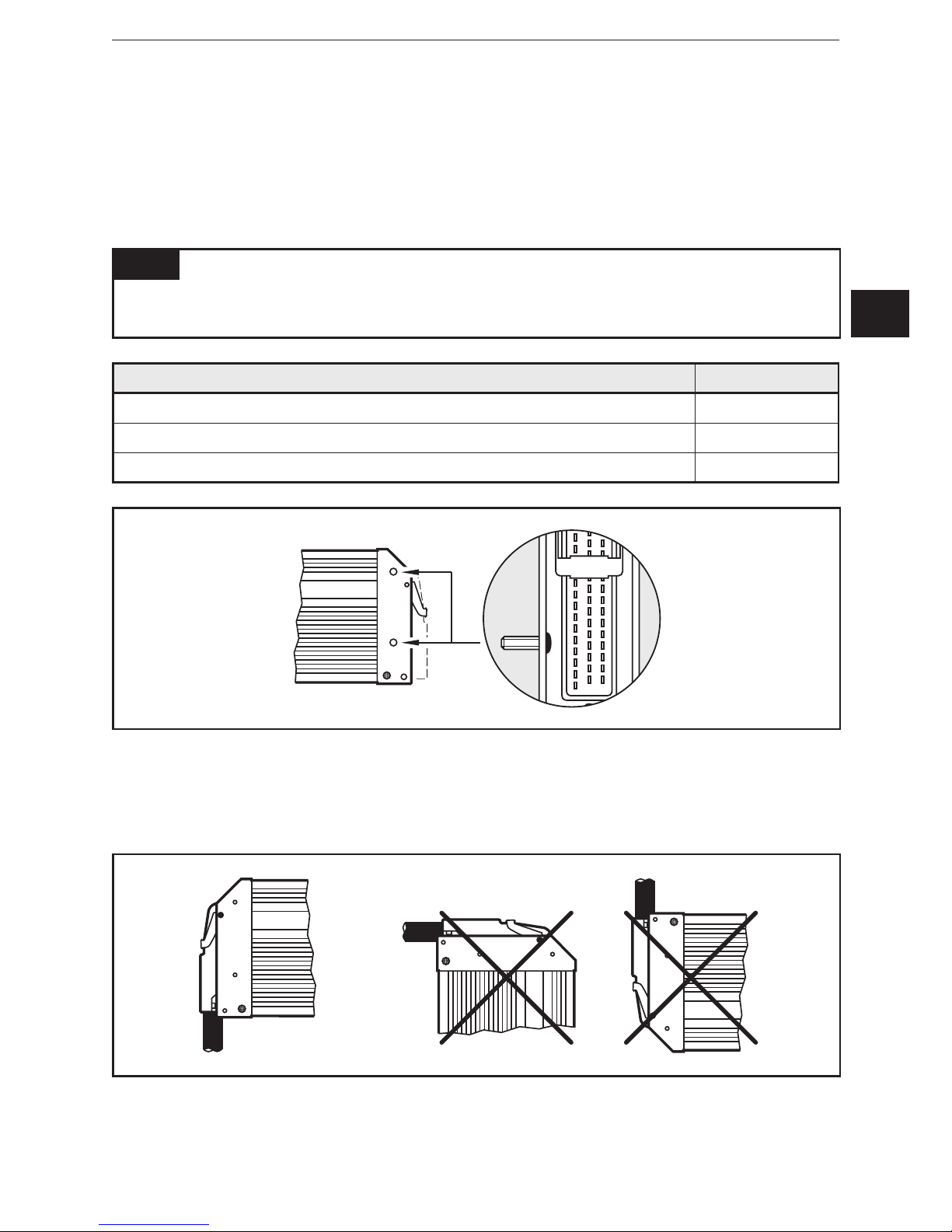
NOTE
Use screws with a low head to avoid that the connector is damaged when placed
and locked�
Screws to be used (examples) Standard
Button head hexagon socket screws (M5 x L) ISO 7380
Cylinder screws with hexagon socket and low head (M5 x L) DIN 7984
Cutting screws for metric ISO thread with low head DIN 7500
Example button head hexagon socket screw
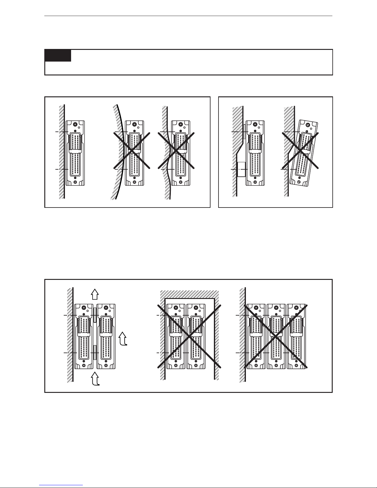
4.2 Installation position
► Align the controller so that the cable entries of the connectors face downwards�
Preferred installation position
SmartController XL CR2532
8
4.3 Mounting surface
NOTE
The housing must not be exposed to any torsional forces or mechanical stress�
► Use compensating elements if there is no flat mounting surface available�
Mounting surface
4.4 Heat dissipation
► Ensure sufficient heat dissipation as the internal heating of the electronics is
conducted away via the housing�
► In case of sandwich mounting of controllers use spacers�
Heat dissipation and sandwich mounting
UK
SmartController XL CR2532
9
5 Electrical connection
5.1 Wiring
Wiring (→ 7 Technical data)
Only connect the connector pins as shown in the pin layout�
Unspecified connector pins remain unconnected�
► Connect all indicated supply cables and GND terminals (St and Ex connection
side)�
NOTE
Inversion of the Ex and St connection sides can lead to damage to a connected
PC or notebook�
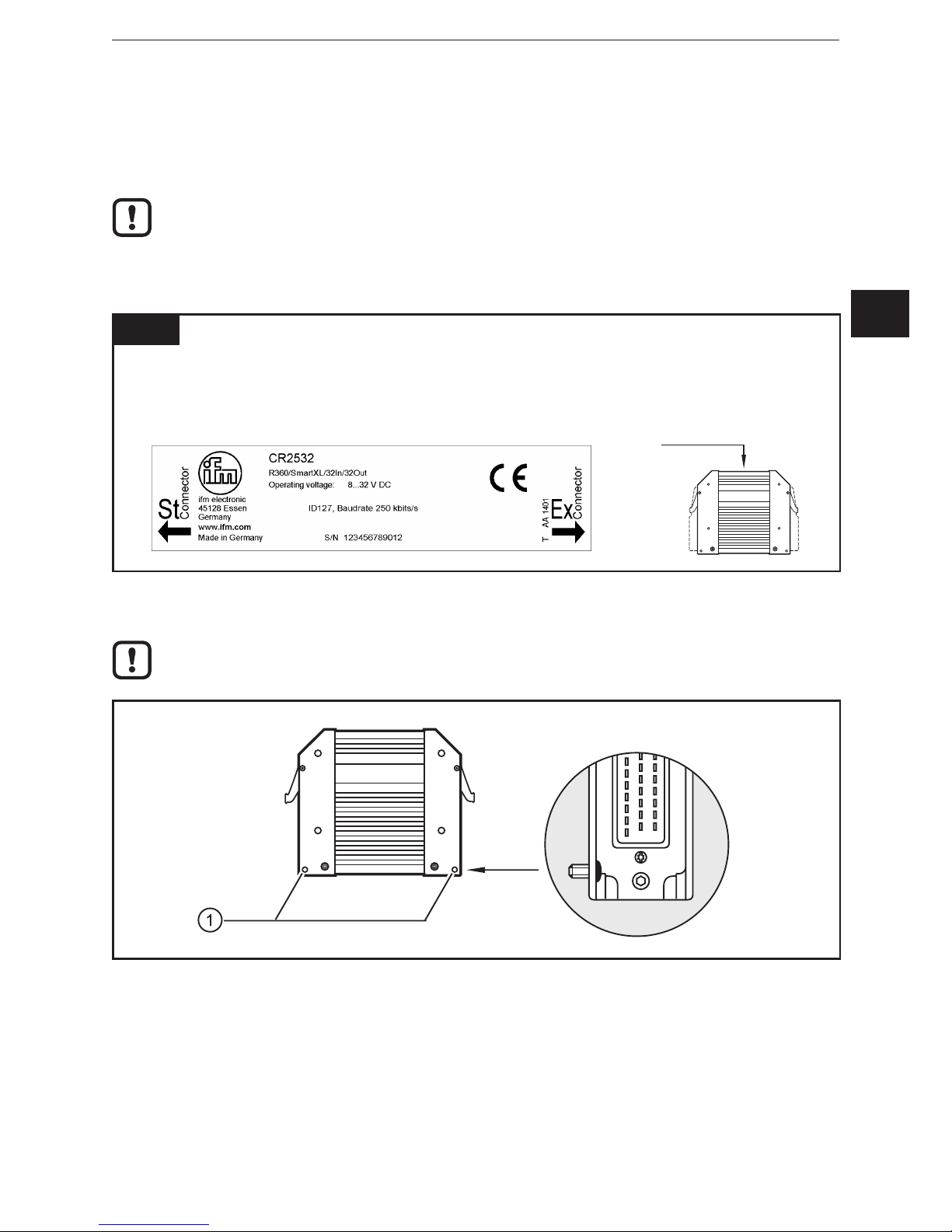
► Note the device label�
Dieser Andruck erfolgte durch Labelprint V 3.32 am 09.01.2014 11:08:57 Uhr auf Server: DETTBMCS10PCX1. Ausgelöst wurde
dieser vollautomatische Vorgang durch den Beschriftungsprozess.
Rev. Projekt-Nr. Änderungs-Nr. Revision Entwickler Bearbeiter Prüfer Änderung
01 150549
Datum 09.01.2014 09.01.2014 09.01.2014
Position St und Ex
geändert
Name dekreujo dekreujo deschnpa
5.2 Ground connection
To ensure the protection of the device against electrical interference, the
housing must be connected to GND (e�g� to the ground of the vehicle)�
1: Drill holes for ground connection
► Establish a connection between the device and the ground of the vehicle using
M5 screws�
Screws to be used (→ 4.1 Fastening)
 Loading...