

Page 1

Geräte-Handbuch
Device manual
Ausgangs-Modul
Output module
CR2511
DEUTSCHENGLISH
Sachnr. 7390254/03 10/2006
R
Page 2

Inhalt
Bestimmungsgemäße Verwendung / Funktion Seite 3
Technische Daten Seite 4
Maße Seite 5
Montage Seite 5
Elektrischer Anschluß Seite 5
Anschlußbelegung Seite 6
Konfigurationsbeispiele Seite 7
Kenndaten der Ausgänge Seite 8
Betriebsanzeige (Status-LED) Seite 9
Parameter- und EMCY-Objekt-Übersicht Seite 10
Objektverzeichnis
Herstellerspezifische Profile; Index 2000 bis 5FFF Seite 12
Objektverzeichnis
Kommunikationsprofile; Index 1000 bis 1FFF Seite 14
Programmierung (ecolog 100
plus
) Seite 18
Wartung, Instandsetzung und Entsorgung Seite 23
Komformitätserklärung Seite 23
Begriffe und Abkürzungen Seite 24
Notizen Seite 50
AUSGANGS-MODUL CR2511
SEITE 2
Sicherheitshinweise
Diese Beschreibung ist Bestandteil des Gerätes. Sie enthält Texte
und Abbildungen zum korrekten Umgang mit dem Modul und
muß vor einer Installation oder dem Einsatz gelesen werden.
Befolgen Sie die Angaben der Dokumentation. Nichtbeachten der Hinweise,
Verwendung außerhalb der nachstehend genannten bestimmungsgemäßen
Verwendung, falsche Installation oder Handhabung können Beeinträchtigungen der Sicherheit von Menschen und Anlagen zur Folge haben.
Das Gerät darf nur von einer Elektrofachkraft eingebaut, angeschlossen und
in Betrieb gesetzt werden.
Schalten Sie das Gerät extern spannungsfrei bevor Sie irgendwelche Arbeiten
an ihm vornehmen. Schalten Sie ggf. auch unabhängig versorgte Ausgangslastkreise ab.
Bei Fehlfunktion des Geräts oder bei Unklarheiten setzen Sie sich bitte mit
dem Hersteller in Verbindung. Eingriffe in das Gerät können schwerwiegende
Beeinträchtigungen der Sicherheit von Menschen und Anlagen zur Folge
haben. Sie sind nicht zulässig und führen zu Haftungs- und Gewährleistungsauschluß.
Page 3

AUSGANGS-MODUL CR2511
SEITE 3
Bestimmungsgemäße Verwendung / Funktion
Das Ausgangs-Modul CR2511 dient zur dezentralen Ansteuerung von Aktoren
und Proportionalventilen. Über die integrierte Strommessung kann der Spulenstrom überwacht und zur Regelung genutzt werden.
• Das Modul unterstützt binäre und analoge Ausgänge und wird daher in die
Geräteklasse „I/O Modul“ entsprechend CiA DS 401 eingeordnet und gekennzeichnet.
• Das Modul ist in der Funktion der Ausgänge konfigurierbar.
• Es sind 1 Server SDO und 3 Default PDOs gemäß CiA DS 401 eingerichtet.
Das PDO-Mapping kann nicht geändert werden (statisches PDO-Mapping).
Die Default-Identifier sind ensprechend des „Predefined connection set“ vergeben.
• Die COB-IDs der PDOs sowie die Übertragungsart (synch/asynch) der einzelnen
PDOs sind konfigurierbar.
Die Übertragungsart wird spannungsausfallsicher gespeichert. Geänderte PDOs
(PDO-linking) werden nicht spannungsausfallsicher gespeichert.
• Das Modul erwartet ein Synch-Objekt.
Der CAN Identifier des Synch-Objektes ist konfigurierbar. Nach einer Änderung
wird der ID automatisch spannungausfallsicher gespeichert.
• Das Modul unterstützt „Node guarding“.
Die „Guard time“, der „Life time factor“ und der CAN Identifier des Guard
Objektes sind konfigurierbar und werden spannungsausfallsicher gespeichert.
• Das Modul generiert ein Emergency Objekt . Der COB-ID des EMCY-Objektes
ist konfigurierbar.
• Das Modul speichert die 4 zuletzt aufgetretenen Fehler.
Abgelegt wird der Fehlercode des jeweiligen Emergency Objektes.
• Das Ausgangsmodul unterstützt 5 Betriebsarten
- Binäre Ausgänge mit Stromrückmeldung; bis 2 A.
- Binäre Ausgänge ohne Stromrückmeldung; bis 4 A.
- PWM-Ausgänge mit Stromrückmeldung; bis 2 A.
- PWM-Ausgänge ohne Stromrückmeldung; bis 4 A.
- Stromgeregelte PWM-Ausgänge; bis 2 A.
• Das Modul unterstützt eine Reset-Funktion;
d.h. die Belegung der Parameter mit den werkseitigen Default-Werten* nach
Aufforderung.
*) Werkseitige Default-Einstellungen siehe „Parameterliste“, Seite 10
DEUTSCH
Page 4

Technische Daten
AUSGANGS-MODUL CR2511
SEITE 4
Gehäuse
Maße (LxBx H)
Montage
Anschluß
Ausgänge
konfigurierbar als
Betriebsspannung U
B
Überspannung
Stromaufnahme
Betriebstemperatur
Lagertemperatur
Schutzart
Schnittstelle
Baudrate
Kommunikationsprofil
Node-ID (Default)
Status-Anzeige
Feuchtetest
Mechanische Festigkeit
Störfestigkeit
gegen
leitungsgebundene
Störungen
Störfestigkeit gegen
Fremdfeld
Störabstrahlung
geschlossenes, abgeschirmtes Metallgehäuse mit Flanschbefestigung
132 x 43 x 153 mm
Schraubbefestigung mit 4 Stk. M5x L nach DIN 7500 bzw. DIN 7984
Einbaulage waagerecht liegend o. senkrecht stehend auf Montagewand
1 Anschlußstecker 55-polig, verriegelt, verpolsicher
Typ AMP oder Framatome
Kontakte AMP-Junior-Timer, Crimp-Anschluß 0,5/2,5 mm
2
8
digital, plus-schaltend (High-Side)
analog, PWM-Kanal (PWM-Wert 0‰; 50 ...1000‰)
analog, stromgeregelter Kanal (100...2000 mA)
10 ... 30 V DC SELV
≤ 36 V für t ≤ 10 s
≤ 100 mA (ohne externe Last)
-40°C ... +85°C
-40°C ... +90°C
IP 67 (bei gestecktem Stecker mit Einzeladerabdichtung, z.B. EC2084)
CAN Interface 2.0 B, ISO 11898
10 kBit/s ... 1 MBit/s (Defaulteinstellung 125 kBit/s)
CANopen, CiA DS 301 Version 3.0, CiA DS 401 Version 1.4
hex 20 (= 32)
Zweifarben-LED (Rot/Grün)
Prüfnormen und Bestimmungen
≤ 90 % rel. Luftfeuchte, nicht kondensierend, nach IEC 68-2-30
Schwingen nach IEC 68-2-6
Schocken nach IEC 68-2-27
Dauerschocken nach IEC 68-2-29
nach DIN 40839/Teil 1, Impulse 1, 2, 3a, 3b (entspricht ISO 7637)
Schärfegrad 4, Funktionszustand A
nach DIN 40839/Teil 1, Impulse 5 (entspricht ISO 7637)
Schärfegrad 1, Funktionszustand C
nach DIN 40839/Teil 3, Impulse 1, 2, 3a, 3b (entspricht ISO 7637)
Schärfegrad 4, Funktionszustand A
nach Richtlinie 95/54/EG nach EN 61000-6-2
nach Richtlinie 95/54/EG nach EN 50081-1
Page 5
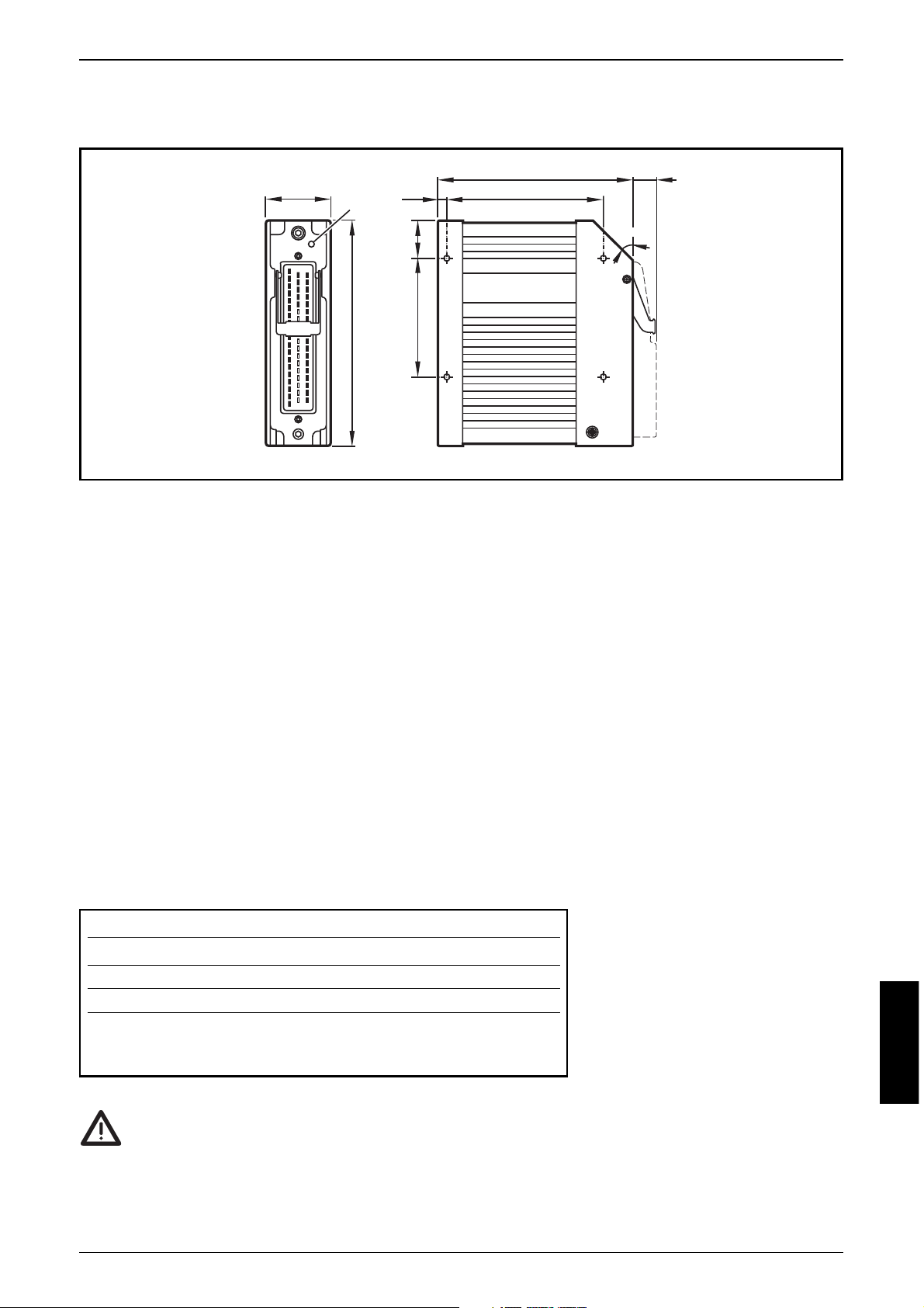
Maße
Montage
Um das Ausgangs-Modul der geringsten mechanischen Belastung auszusetzen,
ist es vorzugsweise waagerecht liegend oder senkrecht stehend auf der Montagewand anzubringen. Dazu müssen vier Schrauben nach DIN 7500 bzw. DIN 7984
(M5xL) benutzt werden.
Wenn möglich sollte die Orientierung des Ausgangs-Moduls so angelegt werden,
daß die Kabeleinführung des Steckers nach unten zeigt.
Da die Eigenerwärmung der Geräteelektronik über das Gehäuse abgeführt wird,
muß bei der „Sandwich-Montage“ von Modulen für ausreichende Kühlung
gesorgt werden.
Elektrischer Anschluß
Um den elektrischen Störschutz des Gerätes sicherzustellen, muß
das Gehäuse mit GND verbunden werden (z.B. der Fahrzeugmasse).
Zum Schutz des gesamten Systems (Verkabelung und Modul) sind die einzelnen
Stromkreise mit max. 16 A abzusichern.
AUSGANGS-MODUL CR2511
SEITE 5
DEUTSCH
Bezeichnung Pin-Nr. Potential
Versorgungsspannung 23 +VBB
S
Masse 01 GND
S
Versorgungsspannung Ausgänge 05 +VBB
O
CAN-Interface 14 / 51 CAN_H
32 / 50 CAN_L
15 / 33 CAN_GND
43
LED
153
5,5
26
±0,5
80
132
106,5
±1
±1
45
15
°
Page 6
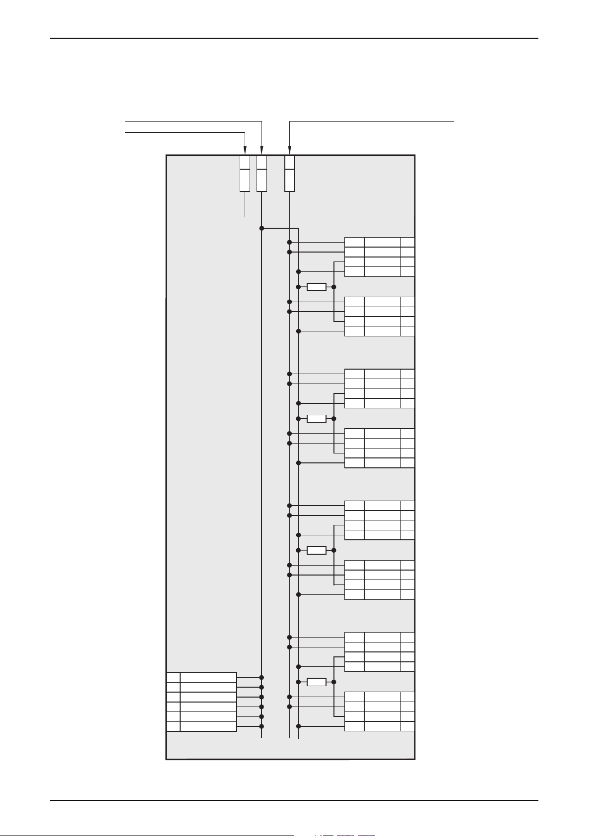
Anschlußbelegung
.
AUSGANGS-MODUL CR2511
SEITE 6
Supply
Output
Supply +DC
Supply GND
CAN
Interface
23
VBB
S
01
GND
S
05
02
38
20
08
Channel 1
Output +DC
OUT
Current
GND
CAN_GND
50
15
14
32
33
51
CAN_H
CAN_L
CAN_H
CAN_L
CAN_GND
VBB
O
VBB
O
VBBSGND
S
1
1
+VBB
O
03
39
21
27
OUT
Current
GND
2
2
+VBB
O
04
40
22
09
OUT
Current
GND
3
3
+VBB
O
25
41
42
28
OUT
Current
GND
4
4
+VBB
O
16
52
34
10
OUT
Current
GND
5
5
+VBB
O
17
53
35
29
OUT
Current
GND
6
6
+VBB
O
18
54
36
11
OUT
Current
GND
7
7
+VBB
O
19
55
37
30
OUT
Current
GND
8
8
+VBB
O
Channel 2
Channel 3
Channel 4
Channel 5
Channel 6
Channel 7
Channel 8
Page 7
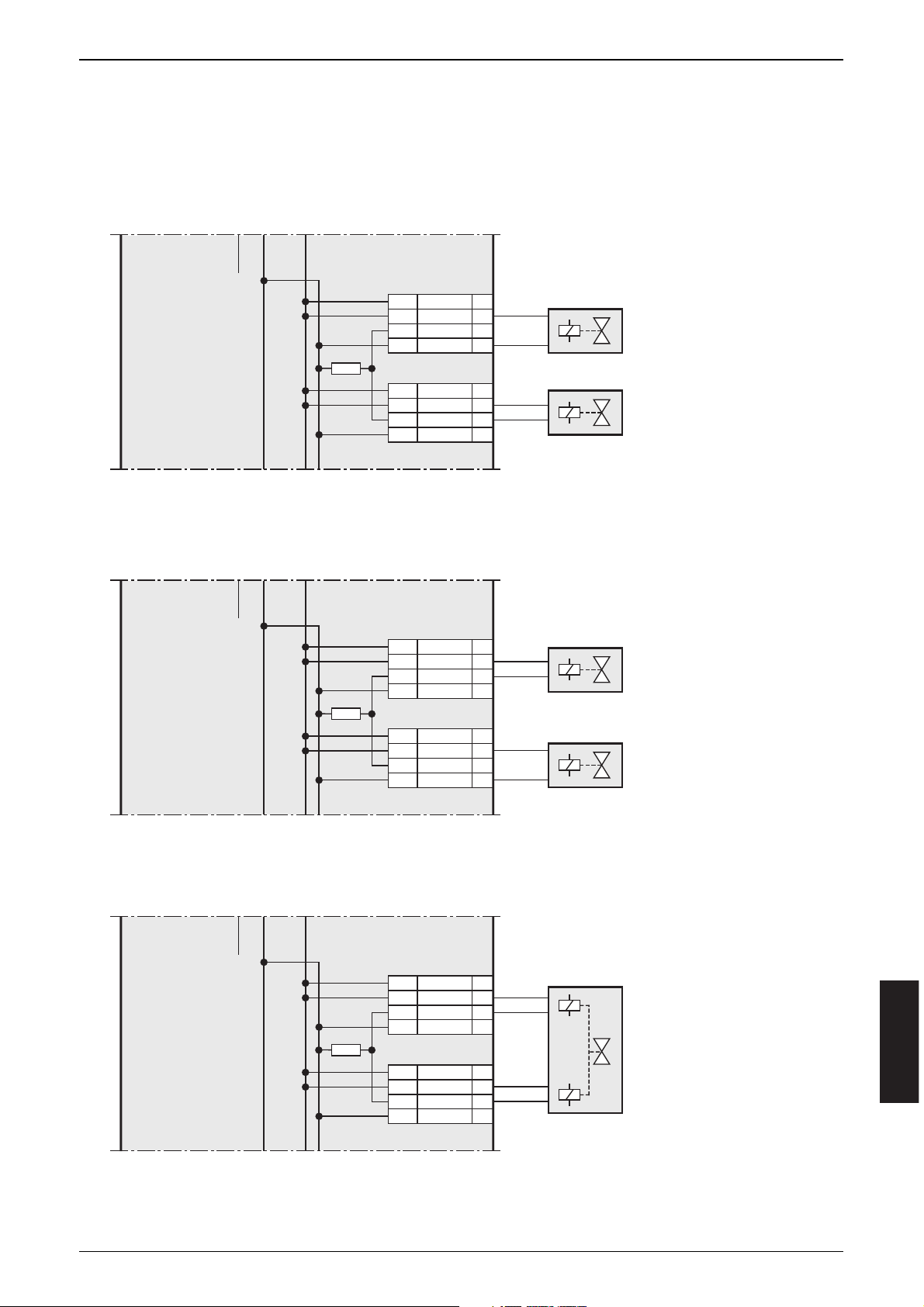
Konfigurationsbeispiele
DEUTSCH
AUSGANGS-MODUL CR2511
SEITE 7
02
38
20
08
OUT
Current
GND
VBB
O
VBBSGND
S
1
1
+VBB
O
03
39
21
27
OUT
Current
GND
2
2
+VBB
O
Channel 1
Channel 2
02
38
20
08
OUT
Current
GND
VBB
O
VBBSGND
S
1
1
+VBB
O
03
39
21
27
OUT
Current
GND
2
2
+VBB
O
Channel 1
Channel 2
02
38
20
08
Channel 1
OUT
Current
GND
VBB
O
VBBSGND
S
1
1
+VBB
O
03
39
21
27
OUT
Current
GND
2
2
+VBB
O
Channel 2
Digital
z.B. Wegeventil
Digital
z.B. Wegeventil
mit Stromüberwachung
PWM
oder Stromgeregelt
z.B. Proportionalventil
Digital
z.B. Wegeventil
PWM
oder Stromgeregelt
z.B. Proportionalventil
Beispiel 1
Beispiel 2
Beispiel 3
Ausgangsfunktion
Page 8

Kenndaten der Ausgänge
■■
Digital-Ausgänge
8 Halbleiterausgänge; kurzschluß- und überlastfest.
Schaltspannung 10 ... 30 V DC
Schaltstrom max. 2/4 A (mit/ohne Stromüberwachung)
Summenstrom max. 16 A
Stromüberwachung von jeweils 2 Kanälen über die Anschlüsse wählbar,
dabei sind folgende Kanäle zusammengefasst: 1+2, 3+4, 5+6, 7+8
■■
PWM-Ausgänge
Bei der Konfiguration als PWM-Ausgang sind jeweils zwei Ausgänge zusammengefaßt. Das Ausgangssignal wird an einen der beiden Ausgänge ausgegeben,
während der andere Ausgang „OFF“ ist (Links/Rechts-Funktion, Auf/Ab-Funktion).
Die Ausgänge können jederzeit umgeschaltet werden.
Folgende Kanäle sind zusammengefasst: 1+2, 3+4, 5+6, 7+8
PWM-Frequenz 20 ... 250 Hz
Tastverhältnis 0 ‰; 50...1000 ‰
Auflösung 1 ‰
Laststrom max. 4 A (bezogen auf den PWM-Wert 1000 ‰.)
Bei kleineren PWM-Werten reduziert sich dieser Stromwert.
Wertebereich -1000 ... +1000 ‰
> +1000 ‰ werden auf +1000 ‰ abgerundet.
< -1000 ‰ werden auf -1000 ‰ aufgerundet.
Bei Werten zwischen -50...+50 ‰ wird der Ausgang
ausgeschaltet.
Wertausgabe +50 ... +1000 ‰ auf den ungeradzahligen Ausgängen
(1, 3, 4, 7)
-1000 ... -50 ‰ auf den geradzahligen Ausgängen
(2, 4, 6, 8)
■■
Strom-Ausgänge
Bei der Konfiguration als „stromgeregelter Ausgang“ sind jeweils zwei Ausgänge
zusammengefaßt: 1+2, 3+4, 5+6, 7+8
PWM-Frequenz 20 ... 250 Hz
Regelbereich 100 ... 2000 mA
Regelauflösung 2,5 mA
Einstellauflösung 1 mA
Genauigkeit ± 2% FS
Laststrom max. 2 A
Lastwiderstand min. 12 Ω bei U
B
= 24 V DC, min. 6 Ω bei UB= 12 V DC
AUSGANGS-MODUL CR2511
SEITE 8
Page 9

Wertebereich -2000 ... +2000 mA
> +2000 mA werden auf +2000 mA abgerundet.
< -2000 mA werden auf -2000 mA aufgerundet.
Werte zwischen -100...+100 mA werden als „AUS“
interpretiert
Wertausgabe 100 ... 2000 mA auf den ungeradzahligen Ausgängen
(1, 3, 4, 7)
-2000 ... -100 mA auf den geradzahligen Ausgängen
(2, 4, 6, 8)
Freilaufdiode Um das Messergebnis nicht zu verfälschen,
integriert! darf in der Betriebsart „stromgeregelter Ausgang“ keine
externe Freilaufdiode parallel zur Last geschaltet werden.
Hinweis Digital- und PWM/Strom-Ausgang in einem Anschlusspaar
kombinierbar.
(siehe hierzu „Konfigurationsbeispiele“, Seite 7)
Betriebsanzeigen
Gleichzeitige Ansteuerung der roten und grünen LED ergibt als Farbe orange.
DEUTSCH
AUSGANGS-MODUL CR2511
SEITE 9
LED grün
AUS keine Versorgungsspannung
EIN
Modul im Stand by-Modus
CANopen-Status: PREOPERATIONAL / PREPARED
Ausgänge = AUS
LED rot
AUS Kommunikation ok
EIN
Kommunikation gestört
- NodeGuard-Fehler (wenn NodeGuarding aktiviert ist)
- keine Synch-Objekte (wenn Synch-Überwachung aktiviert ist)
blinkend
2 Hz
Modul aktiv
CANopen-Status: OPERATIONAL
Ausgänge werden aktualisiert
Page 10
Parameter- und EMCY-Objekt-Übersicht
Über die Funktion „Restore“ (s. Objektverzeichnis, Index 1011) können die Parameter (Ausnahme Baudrate und Node-ID) mit den werkseitig hinterlegten
Default-Werten belegt werden. Diese sind dann nach dem nächsten Einschalten
der Versorgungsspannung gültig.
Parameterliste
Life Time Factor 0 wird als 1 interpretiert
Das erste Guardprotokoll wird als “Start Guarding” gewertet, auch wenn zu diesem Zeitpunkt das Guarding noch nicht aktiviert ist (Guardtime = 0).
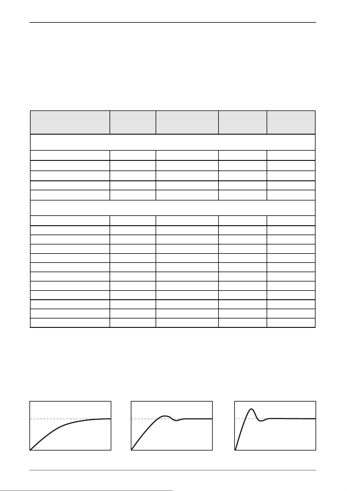
Regelkennlinien (Index 2003)
AUSGANGS-MODUL CR2511
SEITE 10
Parameter
Defaultwert
(werksseitig
eingestellt)
Index
im Objekt-
verzeichnis
Änderung
automatisch
gesichert
Änderung
wirksam
Node-ID 0x20 (= 32)20F0, 20F1 ja nach Reset
20F2, 20F3 ja nach Reset
1005 ja sofort
1006 ja nach Pre-Op
100C ja sofort
100D ja sofort
100E ja sofort
1014 ja sofort
1400 01 nein sofort
1400 02 ja sofort
1401 01 nein sofort
1401 02 ja sofort
1800 01 nein sofort
1800 02 ja sofort
2000 ja nach Pre-Op
2001 ja nach Pre-Op
Baudrate 0x03 (= 125 kBit/s)
COB ID Synch Objekt 0x80
Communication Cycle 0 (Off)
Guard Time 0 (Off)
Life Time Factor 0 (Off)
COB ID Guarding 0x700 + Node ID
COB ID EMCY 0x80 + Node ID
COB ID Rec PDO 1 0x200 + Node ID
Trans Type Rec PDO 1 synchron 1
COB ID Rec PDO 2 0x300 + Node ID
Trans Type Rec PDO 2 synchron 1
COB ID Trans PDO 1 0x180 + Node ID
Trans Type Trans PDO 1 nach Änderung
I/O Konfiguration
Herstellerspezifische Profile; Index 2000 bis 5FFF
Kommunikationsprofile; Index 1000 bis 1FFF
8 binäre Ausgänge
PWM Frequenz 0x64 (= 100 Hz)
2003 ja sofortRegelkennlinie 0x00
(0x00) Default (0x01) (0x02)
I
I
t
t
I
t
Page 11

EMCY Objekt
Folgende Fehlercodes gemäß DSP-401 bzw. DSP-301 werden unterstützt:
Es wird nur der erste Fehler einer Fehlergruppe gemeldet.
Tritt z.B. erst am Kanalpaar 1/2 und dann am Kanalpaar 3/4 der Fehler „Lastwiderstand zu groß“ auf, so wird nur der zuerst aufgetretene Fehler gemeldet.
CANopen sieht nicht vor, daß zwei gleiche EMCY-Objekte hintereinander abgesetzt werden.
DEUTSCH
AUSGANGS-MODUL CR2511
SEITE 11
Zusatz
code
EMCY
Code
Error Reg
Beschreibung
0x8100
0x11
„Monitoring“ (Guarding Error)
- für die „guard time“ x „life time factor“ wird kein
guard objekt empfangen
Reset bei erneuter Kommunikation
0x8200 0x11
0x00
0x6200 0x81
„User Software“
- I/O-Konfiguration ist nicht zulässig
EMCY Objekt beinhaltet fehlerbehaftetes Kanalpaar;
jedes Bit repräsentiert ein Kanalpaar
0000 0010 Kanalpaar 1, 2
0000 1000 Kanalpaar 3, 4
0010 0000 Kanalpaar 5, 6
1000 0000 Kanalpaar 7, 8
bit-codiert
0x00
„Monitoring“ (Synch Error)
- für „communication cycle“ wird kein synch objekt empfangen
Nur in OPEATIONAL
Reset bei Synch-OBJ bzw. PREOP
0xFF00
0x81
bit-codiert
„Device Specific“
- Stromsollwert kann nicht erreicht werden, da
Lastwiderstand zu groß/zu klein
0000 0001 Kanalpaar 1, 2 Lastwiderstand zu groß
0000 0010 Kanalpaar 3, 4 "
0000 0100 Kanalpaar 5, 6 "
0000 1000 Kanalpaar 7, 8 "
0001 0000 Kanalpaar 1, 2 Lastwiderstand zu klein
0010 0000 Kanalpaar 3, 4 "
0100 0000 Kanalpaar 5, 6 "
1000 0000 Kanalpaar 7, 8 "
0x6100 0x11
„Internal Software“:
- Überlauf einer Rx-Queue; z. B. Frequenz der RxPDOs ist zu
groß; Reset nur extern über Eintrag in 1003 00
0x00
0x6101 0x11
„Internal Software“:
- Überlauf einer Tx-Queue; z. B. Gerät kommt nicht auf den Bus;
Reset nur extern über Eintrag in 1003 00
0x00
Page 12

Objektverzeichnis
Herstellerspezifische Profile; Index 2000 bis 5FFF
AUSGANGS-MODUL CR2511
SEITE 12
Index S-Idx Name Ty p Default Beschreibung
2000
0
I/O
Konfiguration
u8, ro
0x08
Anzahl der Einträge (= Anzahl der IO-Kanäle)
1
Ausgangs-
kanal 1
u8, rw 0x02
0 = AUS
2 = Binärausgang
4 = Analogausgang (PWM)
5 = Analogausgang (stromgeregelt)
2
Ausgangs-
kanal 2
u8, rw 0x02
0 = AUS
2 = Binärausgang
4 = Analogausgang (PWM)
5 = Analogausgang (stromgeregelt)
3
Ausgangs-
kanal 3
u8, rw 0x02
0 = AUS
2 = Binärausgang
4 = Analogausgang (PWM)
5 = Analogausgang (stromgeregelt)
4
Ausgangs-
kanal 4
u8, rw 0x02
0 = AUS
2 = Binärausgang
4 = Analogausgang (PWM)
5 = Analogausgang (stromgeregelt)
2001 0
PWM
Frequenz
u8, rw
0x64
(100 Hz)
Einstellung in Hz
Bereich = 20 Hz bis 250 Hz
Werte kleiner 20 Hz oder größer 250 Hz
werden nicht übernommen. Der bisherige Wert
bleibt weiter gültig.
5
Ausgangs-
kanal 5
u8, rw 0x02
0 = AUS
2 = Binärausgang
4 = Analogausgang (PWM)
5 = Analogausgang (stromgeregelt)
6
Ausgangs-
kanal 6
u8, rw 0x02
0 = AUS
2 = Binärausgang
4 = Analogausgang (PWM)
5 = Analogausgang (stromgeregelt)
7
Ausgangs-
kanal 7
u8, rw 0x02
0 = AUS
2 = Binärausgang
4 = Analogausgang (PWM)
5 = Analogausgang (stromgeregelt)
8
Ausgangs-
kanal 8
u8, rw 0x02
0 = AUS
2 = Binärausgang
4 = Analogausgang (PWM)
5 = Analogausgang (stromgeregelt)
Erläuterung der Abkürzungen:
0x... = hexadezimaler Zahlenwert
str = String
rw = read-write
ro = read only
u8 = unsigned 8 bit
u16 = unsigned 16 bit
u32 = unsigned 32 bit
(siehe auch „Begriffe und Abkürzungen“, Seite 24)
Page 13

Objektverzeichnis
Herstellerspezifische Profile; Index 2000 bis 5FFF
DEUTSCH
AUSGANGS-MODUL CR2511
SEITE 13
Index S-Idx Name Ty p Default Beschreibung
20F0 0
Einstellung
Node ID
u8, rw
0x20
(= 32)
20F1 0
Einstellung
Node ID
u8, rw
0x20
(= 32)
Node ID unter dem das Modul im
CANopen Netz angesprochen wird;
eine Änderung wird nur dann übernommen,
wenn in den Einträgen 20F0 und 20F1 der
gleiche geänderte Wert eingetragen ist.
Werte kleiner 1 / größer 127 werden nicht
übernommen; die bestehende Einstellung
bleibt erhalten.
Damit die neuen Einträge gültig werden, muss
nach Einstellung der Node ID ein Reset ausgelöst werden (Aus-/Einschalten des Moduls).
20F2 0
Einstellung
Baud Rate
u8, rw 0x03
20F3 0
Einstellung
Baud Rate
u8, rw 0x03
Baud Rate des CAN-Netzes;
eine Änderung wird nur dann übernommen,
wenn in den Einträgen 20F2 und 20F3 der
gleiche geänderte Wert eingetragen ist.
Werte größer 7 werden nicht übernommen;
die bestehende Einstellung bleibt erhalten.
Damit die neuen Einträge gültig werden, muss
nach Einstellung der Baudrate ein Reset ausgelöst werden (Aus-/Einschalten des Moduls).
0 = 1000 kBaud
1 = 500 kBaud
2 = 250 kBaud
3 = 125 kBaud
4 = 100 kBaud
5 = 50 kBaud
6 = 20 kBaud
7 = 10 kBaud
2002
0
Strom-
Istwerte
u8, ro 0x04
Anzahl der Einträge
(= Anzahl der Strom-Meßkanäle)
1
StromIstwert
Kanal 1/2
u16, ro
Stromwerte in mA
2
StromIstwert
Kanal 3/4
u16, ro
Stromwerte in mA
3
StromIstwert
Kanal 5/6
u16, ro
Stromwerte in mA
4
StromIstwert
Kanal 7/8
u16, ro
Stromwerte in mA
2003 0
Regel-
Kennlinie
u8, rw 0x00
0 = lange Ausregelzeit; stabil
1 = mittlere Ausregelzeit; stabil
2 = kurze Ausregelzeit; Überschwingen
(siehe auch „Regelkennlinien“; Seite 10)
Page 14
AUSGANGS-MODUL CR2511
SEITE 14
Objektverzeichnis
Kommunikationsprofile; Index 1000 bis 1FFF
Index S-Idx Name Ty p Default Beschreibung
1000 0 device type u32, ro 0xF0191
Prof. 401;
Ein- und Ausgänge, binär und analog
1003
0
pre-defined
errorfield
u8, ro 0x04
es wird eine Fehlerliste mit 4 Einträgen unterstützt
1004
0
number of
PDOs
u32, ro 0x20001 1 Sende-PDOs, 2 Empfangs-PDOs
1
number of
synch. PDOs
u32, ro 0x20001 alle PDOs können sychron übertragen werden
2
number of
asynch. PDOs
u32, ro 0x20001
alle PDOs können asynchron übertragen
werden
1005 0
COB ID
synch objekt
u32, rw
0x80000080
- Modul erwartet Synch Meldung (Bit 31 = 1)
- Modul generiert keine Synch Meldung
(Bit 30 = 0)
- 11 Bit Identifier System (Bit 29 = 0)
- Identifier der Synch-Meldung
1006 0
Communic.
Cycle
u32, rw
0x00000000
max. Zeit zwischen 2 Synch. Objekten in µs;
Nutzauflösung = 1 ms
1008 0 device name str, ro
CR2511
Gerätebezeichnung
1009 0 HW version str, ro
HW_Ver x.x
Hardeware Version
100A 0 SW version str, ro
SW_Ver x.x
Software Version
100B 0 Node ID u32, ro nur zur Abfrage
100C 0 guard time u16, rw
0x0000
Zeit in ms;
das Modul erwartet innerhalb dieser Zeit ein
„node guarding“ des Netz-Masters;
wird hier der Wert 0 eingetragen, wird diese
Funktion nicht unterstützt
1-4 error history u32, ro 0x00
aufgetretener Fehler; codiert entsprechend
EMCY-Liste; der zuletzt aufgetretene Fehler
steht jeweils in SubIndex 1
1001 0 error register u8, ro 0x00
bitcodiert gemäß Prof.301; unterstützt wird:
0b 0000 0000 kein Fehler
0b 0000 0001 generic error
0b 0001 0000 communication error
0b 1000 0000 manufacturer specific
Page 15

DEUTSCH
AUSGANGS-MODUL CR2511
SEITE 15
Objektverzeichnis
Kommunikationsprofile ; Index 1000 bis 1FFF
Index S-Idx Name Ty p Default Beschreibung
100F 0
number of
SDOs
nicht implementiert; es wird nur das Default
SDO unterstützt
1010
0
number of
save-options
u8, ro 0x01 Anzahl der Optionen „Sichern“
1
“save all
parameters”
u32, rw 0x02
alle Parameter werden bei einer Änderung
automatisch gesichert.
1011
0
number of
restore-options
u8, ro 0x01 Anzahl der Optionen „Restore“
1200
0 Server SDOs u8, ro 0x02 Anzahl der Einträge
1400
0
Receive
PDO 1
u8, ro 0x02
Anzahl der Einträge Rec PDO1;
Binärausgänge
1
COB ID
Rec SDO
u32, ro
0x600
+ID
- SDO ist gültig (Bit 31 = 0)
- CAN ID des Receive SDOs
1 COB ID u32, rw
0x200
+ Node ID
- PDO ist gültig (Bit 31 = 0)
- CAN ID des 1. Rec PDOs
2 Trans Type u8, rw 0x01
0x00 = synch acyclic
0x01...0xF0 = synch cyclic; Anzahl der
Synchobjekte zwischen zwei Zugriffen
0xFC / 0xFD nicht implementiert
0xFE = asynch manuf. spec. event; Ausgänge
werden sofort aktualisiert
0xFF = asynch device profile event; Ausgänge
werden sofort aktualisiert
2
COB ID
Trans SDO
u32, ro
0x580
+ Node ID
- SDO ist gültig (Bit 31 = 0)
- CAN ID des Transmit SDOs
1014 0
COB ID
Emergency
u32, rw
0x40000080
+ Node ID
- Modul reagiert nicht auf fremde EMCY
Mess. (Bit 31 = 0)
- Modul generiert EMCY Mess. (Bit 30 = 1)
- 11 Bit ID (Bit 29 = 0)
- ID = 0x80 + Node ID
CAN-Identifier kann vom Benutzer geändert
werden.
1
“reset for all
parameters”
u32, rw 0x01
Wird hier der String „load“ eingetragen,
werden die Parameter mit den werkseitigen
Voreinstellungen belegt und sind nach dem
nächsten Reset gültig.
100E
0
COB ID
guarding
u32, rw
0x00000700
+ Node ID
CAN Identifier des Node Guard-Objektes
100D 0
life time
factor
u8, rw
0x00
Wenn für „guard time“ x „life time“ kein
„node guarding“ empfangen wird, schaltet das
Modul die Ausgänge aus. Der
CANopen State wird nicht geändert.
Das Produkt aus „guard time“ x „life time“
muß in dem Bereich 0 ... 65535 liegen.
Page 16

AUSGANGS-MODUL CR2511
SEITE 16
Objektverzeichnis
Kommunikationsprofile; Index 1000 bis 1FFF
Index S-Idx Name Ty p
Default
(Hex)
Beschreibung
1401
0
Receive
PDO 2
u8, ro 0x02
Anzahl der Einträge Rec PDO2;
Analogausgänge
1600
0
Mapping
Receive PDO 1
u32, ro 0x01
Anzahl der in das Binär-Ausgangs-PDO
eingebundenen Applikationsobjekte
1
Index im
Objekt-
verzeichnis
u32, ro
0x6200 01
in 6200 SIdx 01 steht 1 Byte (Binärausgänge)
0b 0000 0001 Kanal 1
0b 0000 0010 Kanal 2
0b 0000 0100 Kanal 3
0b 0000 1000 Kanal 4
0b 0001 0000 Kanal 5
0b 0010 0000 Kanal 6
0b 0100 0000 Kanal 7
0b 1000 0000 Kanal 8
1601
0
Mapping
Receive PDO 2
u32, ro 0x04
Anzahl der in des Analog-Ausgangs-PDO
eingebundenen Applikations-Objekte
1
Index im
Objekt-
verzeichnis
u32, ro
0x6411 01
in 6411 SIdx 01 steht der Sollwert des
Analogausgangs Kanal 1 oder 2;
der Wert wird als Tastverhältniss in ‰ oder
als Stromsollwert interpretiert
(abhängig von der Konfiguration des Index
2000, s. Seite 12).
2
Index im
Objekt-
verzeichniss
u32, ro
0x6411 02
in 6411 SIdx 02 steht der Sollwert des
Analogausgangs Kanal 3 oder 4;
der Wert wird als Tastverhältniss in ‰ oder
als Stromsollwert interpretiert
(abhängig von der Konfiguration des Index
2000, s. Seite 12).
3
Index im
Objekt-
verzeichnis
u32, ro
0x6411 03
in 6411 SIdx 03 steht der Sollwert des
Analogausgangs Kanal 5 oder 6;
der Wert wird als Tastverhältniss in ‰ oder
als Stromsollwert interpretiert
(abhängig von der Konfiguration des Index
2000, s. Seite 12).
4
Index im
Objekt-
verzeichnis
u32, ro
0x6411 04
in 6411 SIdx 04 steht der Sollwert des
Analogausgangs Kanal 7 oder 8;
der Wert wird als Tastverhältniss in ‰ oder
als Stromsollwert interpretiert
(abhängig von der Konfiguration des Index
2000, s. Seite 12).
1 COB ID u32, rw
0x300
+ Node ID
- PDO ist gültig (Bit 31 = 0)
- CAN ID des 2. Rec PDOs
2 Trans Type u8, rw 0x01
0x00 = synch acyclic
0x01...0xF0 = synch cyclic; Anzahl der
Synchobjekte zwischen zwei Zugriffen
0xFC / 0xFD nicht implementiert
0xFE = asynch manuf. spec. event; Ausgänge
werden sofort aktualisiert
0xFF = asynch device profile event; Ausgänge
werden sofort aktualisiert
Page 17

DEUTSCH
AUSGANGS-MODUL CR2511
SEITE 17
Objektverzeichnis
Kommunikationsprofile; Index 1000 bis 1FFF
Index S-Idx Name Ty p Default Beschreibung
1800
0
Transmit
PDO 1
u8, ro 0x02
Anzahl der Einträge Trans PDO1;
(Strom-Istwerte)
1 COB ID u32, rw
0x180
+ Node ID
- PDO ist gültig (Bit 31 = 0)
- CAN ID des 1. Trans PDOs
2 Trans Type u8, rw 0x01
0x00 = synch acyclic
0x01...0xF0 = synch cyclic; Anzahl der
Synchobjekte zwischen zwei Zugriffen
0xFC / 0xFD nicht implementiert
0xFE = asynch manuf. spec. event; Ausgänge
werden sofort aktualisiert
0xFF = asynch device profile event; Ausgänge
werden sofort aktualisiert
1A00
0
Mapping
Transmit PDO 1
u32, ro 0x04
Anzahl der eingebundenen
Applikations-Objekte
1
Index im
Objekt-
verzeichnis
u32, ro
0x2002 01
0x2002 02
0x2002 03
0x2002 04
in Idx 2002 01 steht der Strom-Istwert Kanal 1/2
in Idx 2002 02 steht der Strom-Istwert Kanal 3/4
in Idx 2002 03 steht der Strom-Istwert Kanal 5/6
in Idx 2002 04 steht der Strom-Istwert Kanal 7/8
Page 18

AUSGANGS-MODUL CR2511
SEITE 18
Programmierung (ecolog 100
plus
)
Allgemeines
Das E/A-Modul muß als CANopen-Slave mit den CANopen-Startfunktionen
„COP_MSTR_BOOTUP“ und „COP_MSTR_MAIN“ vom R 360-Master initialisiert
und in den Zustand „OPERATIONAL“ versetzt werden (LED blinkt grün; 2 Hz).
Programmier-Funktion
Wird die Funktion „CR2511“ in das Programm eingebunden, sorgt diese automatisch für eine ständige Aktualisierung der Ein-/Ausgangswerte in der Steuerung. Die Funktion „CR2511“ befindet sich in der Bibliothek „CR2511_C.lib“ der
ifm-Programmiersoftware ecolog 100
plus
.
Werden keine Konfigurationsdaten an das E/A-Modul übertragen, arbeitet das
Gerät mit den werksseitigen Default-Einstellungen.
Vor der Inbetriebnahme ist gegebenenfalls die werksseitige Node ID des E/AModuls zu ändern und die Baudrate von Master und Modul auf Gleichheit zu
prüfen bzw. einzustellen.
Defaultwerte: Node ID = 0x20 (= 32)
Baudrate = 0x03 (= 125 kBit/s)
Screenshot der ecolog 100
plus
Programmieroberfläche
Page 19

DEUTSCH
AUSGANGS-MODUL CR2511
SEITE 19
Datenstrukturen
Die Übergabe von CR2511-Konfigurations- und E/A-Daten erfolgt über Datenstrukturen. Im Deklarationsteil muß die Struktur – ebenso wie andere Variablentypen – deklariert werden. Für Konfigurationsdaten kann im Deklarationsteil bereits
eine Wertzuweisung enthalten sein.
Im Programmablauf kann der Zugriff auf eine Strukturkomponente z.B. wie dargestellt erfolgen.
Weitere ecolog 100
plus
Programmierbeispiele für das E/A-Modul erhalten Sie auf Nachfrage von der
ifm electronic gmbh.
Screenshot der ecolog 100
plus
Programmieroberfläche
Page 20

AUSGANGS-MODUL CR2511
SEITE 20
■ Funktion: CR2511
■ Library: CR2511_C.lib
■ Zweck: Parametriert und liest
die Konfigurations- und E/A-Daten
des Ein-/Ausgangs-Moduls
CR2511
■ Parameter
Name Datentyp Beschreibung
Eingänge
ENABLE BOOL TRUE: Funktion wird abgearbeitet
INIT BOOL TRUE: Funktionsinialisierung
FALSE: zyklischer Funktionsaufruf
NODE_ID BYTE Knotenpunkt-Identifier
CFG_READ BOOL TRUE: aktuelle Konfiguration des E/A-Moduls lesen
CFG_WRITE BOOL TRUE: aktuelle Konfiguration des E/A-Moduls schreiben
CFG_DATA DWORD Adresse der Konfigurationsdaten (Datenstruktur)
RX_TYPE BYTE Receive Transmission Type (Default = 0; synch acyclic)
TX_TYPE BYTE Transmit Transmission Type (Default = 1; synch cyclic)
SYNC BOOL CANopen-Synchronisationstakt
(Systemvariable COB_SYNC)
IO_DATA DWORD Adresse der Ein-/Ausgangsdaten (Datenstruktur)
Ausgänge
CFG_RESULT BYTE 1 = Konfiguration wurde erfolgreich
gelesen oder geschreiben
2 = Konfiguration wurde noch nicht
gelesen oder geschreiben
3 = Konfiguration kann nicht gelesen oder geschrieben
werden (fehlende bzw. falsche Node ID oder Gerät
defekt)
IO_RCV BOOL True: für einen Zyklus, wenn neue Daten gesendet wurden.
CR2511
ENABLE CFG_RESULT
INIT IO_RCV
NODE_ID
CFG_READ
CFG_WRITE
CFG_DATA
RX_TYPE
TX_TYPE
SYNC
IO_DATA
Wenn nicht anders beschrieben, ist ein „FALSE“-Signal bei boolschen Datentypen
stets die Negierung des beschriebenen „TRUE“-Signals.
Page 21

DEUTSCH
AUSGANGS-MODUL CR2511
SEITE 21
■ Datenstruktur:
CR2511 ConfigStruct
■ Zweck:
Parameter- und Konfigurationsdaten
können geschrieben/gelesen werden.
Die Datenstruktur wird dem Funktionseingang „CFG_DATA“ über den ADROperator zugewiesen.
■ Strukturkomponenten
Name Datentyp Beschreibung
GUARDTIME TIME Guardingzeit des E/A-Moduls [mSek.]
LIFETIME BYTE Lifetime des E/A-Moduls
Ch1 BYTE Konfig. Kanal 1 0 = disabled (Aus)
2 = binärer Ausgang *
4 = analoger Ausgang (PWM)
5 = analoger Ausgang (PWM; stromgeregelt)
Ch2 BYTE Konfig. Kanal 2 0, 2*, 4, 5 (wie Ch1)
Ch3 BYTE Konfig. Kanal 3 0, 2*, 4, 5 (wie Ch1)
Ch4 BYTE Konfig. Kanal 4 0, 2*, 4, 5 (wie Ch1)
Ch5 BYTE Konfig. Kanal 5 0, 2*, 4, 5 (wie Ch1)
Ch6 BYTE Konfig. Kanal 6 0, 2*, 4, 5 (wie Ch1)
Ch7 BYTE Konfig. Kanal 7 0, 2*, 4, 5 (wie Ch1)
Ch8 BYTE Konfig. Kanal 8 0, 2*, 4, 5 (wie Ch1)
PwmFrq BYTE PWM-Frequenz in Hz;
Bereich = 20 bis 250 Hz (100 Hz)*
Hinweis: Modus 5 steht nur zur Verfügung, wenn der Anschluß über
die Ausgänge mit Stromüberwachung erfolgt
(siehe auch Seite 6, Anschlußbelegung).
*) Default
TYPE CR2511 ConfigStruct
STRUCT
GUARDTIME: TIME;
LIFETIME: BYTE;
Ch1: BYTE; (*2000/1*) (*0,2,4,5*)
Ch2: BYTE; (*2000/2*) (*0,2,4,5*)
Ch3: BYTE; (*2000/3*) (*0,2,4,5*)
Ch4: BYTE; (*2000/4*) (*0,2,4,5*)
Ch5: BYTE; (*2000/5*) (*0,2,4,5*)
Ch6: BYTE; (*2000/6*) (*0,2,4,5*)
Ch7: BYTE; (*2000/7*) (*0,2,4,5*)
Ch8: BYTE; (*2000/8*) (*0,2,4,5*)
PwmFrq: BYTE; (*2001/0*)
END_STRUCT
END_TYPE
Page 22

AUSGANGS-MODUL CR2511
SEITE 22
■ Datenstruktur:
CR2511 InOutStruct
■ Zweck:
Aktuelle E/A-Daten werden gelesen
bzw. geschrieben.
Die Datenstruktur wird dem Funktionseingang „IO_DATA“ über den ADROperator zugewiesen.
■ Strukturkomponenten
TYPE CR2511 InOutStruct
STRUCT
BinOut1: BOOL;
BinOut2: BOOL;
BinOut8: BOOL;
AnaOut1_2: INT;
AnaOut3_4: INT;
AnaOut5_6: INT;
AnaOut7_8: INT;
AnaIn1_2: WORD;
AnaIn3_4: WORD;
AnaIn5_6: WORD;
AnaIn7_8: WORD;
END_STRUCT
END_TYPE
Name Datentyp Beschreibung
BinOut1 BOOL Ausgangsstatus Kanal 1 (wenn Ch1 Konfiguration = 2)
BinOut2 BOOL Ausgangsstatus Kanal 2 (wenn Ch2 Konfiguration = 2)
BinOut3 BOOL Ausgangsstatus Kanal 3 (wenn Ch3 Konfiguration = 2)
BinOut4 BOOL Ausgangsstatus Kanal 4 (wenn Ch4 Konfiguration = 2)
BinOut5 BOOL Ausgangsstatus Kanal 5 (wenn Ch5 Konfiguration = 2)
BinOut6 BOOL Ausgangsstatus Kanal 6 (wenn Ch6 Konfiguration = 2)
BinOut7 BOOL Ausgangsstatus Kanal 7 (wenn Ch7 Konfiguration = 2)
BinOut8 BOOL Ausgangsstatus Kanal 8 (wenn Ch8 Konfiguration = 2)
AnaOut1_2 INT analoger Ausgangswert (wenn Ch1_2 Konfig. = 4 oder 5)
Kanal 1 oder 2
AnaOut3_4 INT analoger Ausgangswert (wenn Ch3_4 Konfig. = 4 oder 5)
Kanal 3 oder 4
AnaOut5_6 INT analoger Ausgangswert (wenn Ch5_6 Konfig. = 4 oder 5)
Kanal 5 oder 6
AnaOut7_8 INT analoger Ausgangswert (wenn Ch7_8 Konfig. = 4 oder 5)
Kanal 7 oder 8
Hinweis: Die ungeradzahligen Kanäle 1, 3, 5, 7 sind aktiv,
wenn mit der Variablen ein positiver Wert übergeben wird.
Die geradzahligen Kanäle 2, 4, 6, 8 sind aktiv,
wenn mit der Variablen ein nagativer Wert übergeben wird.
AnaIn1_2 WORD Strom-Istwert [mA], Kanal 1 oder 2
AnaIn3_4 WORD Strom-Istwert [mA], Kanal 3 oder 4
AnaIn5_6 WORD Strom-Istwert [mA], Kanal 5 oder 6
AnaIn7_8 WORD Strom-Istwert [mA], Kanal 7 oder 8
Hinweis: Der Strom-Istwert ist nur lesbar, wenn der Anschluß über die
Ausgänge mit Stromüberwachung erfolgt (siehe auch Seite 6,
Anschlußbelegung).
Page 23

DEUTSCH
AUSGANGS-MODUL CR2511
SEITE 23
Wartung, Instandsetzung und Entsorgung
Da innerhalb des Moduls keine vom Anwender zu wartenden Bauteile enthalten
sind, darf das Gehäuse nicht geöffnet werden. Die Instandsetzung des Moduls
darf nur durch den Hersteller durchgeführt werden.
Die Entsorgung muß gemäß den nationalen Umweltvorschriften erfolgen.
Konformitätserklärung
Das CE-Zeichen wird angebracht auf Basis der EMV-Richtlinie EMV 89/336/EWG,
realisiert in den Normen EN 50081-1 und EN 61000-6-2 sowie der Niederspannungsrichtlinie NS73/23/EWG realisiert in der Norm EN 61010.
Page 24

AUSGANGS-MODUL CR2511
SEITE 24
Begriffe und Abkürzungen
0b ... binärer Zahlenwert (zur Bitcodierung), z.B. 0b0001 0000
0x ... hexadezimaler Zahlenwert, z.B. 0x64 (= 100 dezimal)
Baudrate Übertragungsgeschwindigkeit (1 Baud = 1 Bit/sec.)
CAL CAN Application Layer
CAN basierendes Netzwerkprotkoll auf Applikationsebende
CAN Controller Area Network (Bussystem für den Einsatz im Mobilbereich)
CAN_H CAN-High; CAN-Anschluß/-Leitung mit dem hohen Spannungspegel
CAN_L CAN-Low; CAN-Anschluß/-Leitung mit dem niederen Spannungspegel
CANopen CAN basierendes Netzwerkprotokoll auf Applikationsebene mit einer offe-
nen Konfigurationsschnittstelle (Objektverzeichnis).
CiA "CAN in Automation e.V."
(Anwender- und Herstellerorganisation in Deutschland/Erlangen)
Definitions- und Kontrollorgan für CAN und CAN-basierende Netzwerkprotokolle
CiA DS Draft Standard (veröffentlichte CiA-Spezifikation, die in der Regel ein Jahr
nicht geändert und erweitert wurde)
CiA DSP Draft Standard Proposal (veröffentlichter CiA-Spezifikationsentwurf)
CiA WD Work Draft (CiA-intern zur Diskussion akzeptiertes Arbeitspapier)
CiA DS 301 Spezifikation zum CANopen Kommunikationsprofil;
beschreibt die grundlegenden Kommunikationsmechanismen zwischen den
Netzwerkteilnehmern, wie z.B die Übertragung von Prozessdaten in Echtzeit,
den Datenaustausch zwischen Geräten oder die Konfigurationsphase.
Entspr. der Applikation ergänzt mit den nachfolgenden CiA-Spezifikationen:
CiA DS 401 Geräteprofil für digitale und analoge E/A-Baugruppen
CiA DS 402 Geräteprofil für Antriebe
CiA DS 403 Geräteprofil für Bediengeräte
CiA DS 404 Geräteprofil für Messtechnik und Regler
CiA DS 405 Spezifikation zur Schnittstelle zu programmierbaren Systemen (IEC1131)
CiA DS 406 Geräteprofil für Drehgeber/Encoder
CiA DS 407 Applikationsprofil für den öffentlichen Nahverkehr
COB CANopen Communication Object (PDO, SDO, EMCY, ...)
COB ID CANopen Identifier eines Communication Objects
Communication cycle Die zu überwachende Synchronisationszeit; max. Zeit zwischen 2 Sync-
Objekten
EMCY Object Emergency Object (Alarmbotschaft; Gerät signalisiert einen Fehler)
Error Reg Error Register (Eintrag mit einer Fehlerkennung)
Guarding Error Knoten bzw. Netzwerkteilnehmer wurde bzw. wird nicht mehr gefunden
Guard-MASTER: Einer oder mehrere SLAVES melden sich nicht mehr.
Guard-SLAVE: Das Gerät (SLAVE) wird nicht mehr abgefragt.
Guard Time Innerhalb dieser Zeit erwartet der Netzwerkteilnehmer ein "Node Guarding"
des Netz-Masters
ID Identifier; kennzeichnet eine CAN-Nachricht. Der numerische Wert des ID
beinhaltet gleichzeitig eine Priorität bezüglich des Bus-Zugriffes.
ID 0 = höchste Priorität.
Identifier siehe ID
Idx Index; bildet zusammen mit dem S-Index die Adresse eines Eintrages im
Objektverzeichniss
Life Time Factor Anzahl der Versuche bei fehlender Guarding Antwort
Monitoring Wird verwendet um die Fehlerklasse (Guarding-Überwachung, Synch-, etc.)
zu beschreiben.
NMT Netzwerk-Management
NMT-Master/-Slaves Der NMT-Master steuert die Betriebzustände der NMT-Slaves
Node Guarding Parametrierbare zyklische Überwachung von Slave-Netzwerkteilnehmern
durch einen übergeordneten Master-Knoten, sowie die Überwachung dieses
Abfragemechanismus durch die Slave-Teilnehmer.
Page 25

DEUTSCH
AUSGANGS-MODUL CR2511
SEITE 25
Node-ID Knotenpunkt-Identifier (Kennung eines Teilnehmers im CANopen Netz)
Objekt (auch OBJ) Oberbegriff für austauschbare Daten/Botschaften innerhalb des CANopen-
Netzwerks
Objektverzeichnis enthält alle CANopen-Kommunikationsparameter eines Gerätes, sowie gerä-
tespezifische Parameter und Daten.
Auf die einzelnen Einträge wird über den Index und S-Index zugegriffen.
Operational Betriebszustand eines CANopen Teilnehmers.
In diesem Modus können SDOs, NMT-Kommandos und PDOs übertragen
werden.
PDO Process Data Object;
im CANopen Netz zur Übertragung von Prozessdaten in Echtzeit, wie z.B.
Drehzahl eines Motors.
PDOs besitzen eine höhere Priorität als SDOs; im Gegensatz zu SDOs werden
sie unbestätigt übertragen. PDOs bestehen aus einer CAN-Nachricht mit
Identifier und bis zu 8 Byte Nutzdaten.
PDO Mapping Beschreibt die Applikationsdaten, die mit einem PDO übertragen werden.
Pre-Op Preoperational; Betriebszustand eines CANopen Teilnehmers.
Nach den Einschalten der Versorgungsspannung geht jeder Teilnehmer automatisch in diesen Zustand.
Im CANopen-Netz können in diesem Modus nur SDOs und NMT-Kommandos übertragen werden, jedoch keine Prozessdaten
Prepared (auch stopped) Betriebszustand eines CANopen Teilnehmers.
In diesem Modus werden nur NMT- Kommandos übertragen.
Rec PDO (Receive) Empfangs Process Data Object
(auch Rx PDO)
ro read only (unidirektional; nur Lesen)
rw read-write (bidirektional; Lesen-Schreiben)
Rx-Queue Empfangspuffer
s16 Datentyp signed 16 bit (mit Vorzeichen, 16 Bit-Format)
SDO Service Data Object;
Mit diesem Objekt wird gezielt auf das Objektverzeichniss eines Netzwerkteilnehmers zugegriffen (lesen/schreiben). Ein SDO kann aus mehreren CANNachrichten bestehen. Die Übertragung der einzelnen Nachrichten wird von
dem angesprochenen Teilnehmer bestätigt.
Mit den SDOs lassen sich Geräte konfigurieren und parametrieren.
Server SDO Mechanismus und Parametersatz um das "eigene" Objektverzeichnis eines
Netzwerkteilnehmers anderen Teilnehmern (Clients) zugänglich zu machen.
S-Idx (auch SIdx) Subindx innerhalb des Objektverzeichnisses eines CANopen fähigen Gerätes
Start Guarding Start der Knotenüberwachung
str Datentyp String (Variable für Zeichenketten, wie z.B. Text "load")
Sync Error Ausbleiben des Sync OBJ innerhalb der parametrierbaren Synchronisations-
zeit
Sync OBJ Synchronisationsobjekt zur netzwerkweit gleichzeitigen Aktualisierung bzw.
Übernahme der Prozessdaten der entsprechend parametrierten PDOs.
Sync Windows Zeitfenster in dem die synchronen PDOs übertragenen werden müssen.
Time Stamp Zeitstempel zum Abgleich evtl. vorhandener Uhren in Netzwerkteilehmern
Trans Type Art der Prozess-Datenübertragung; synchron, asynchron
Trans PDO (Transmit) Sende Process Data Object
(auch Tx PDO)
Trans SDO (Transmit) Sende Service Data Object
(auch Tx SDO)
Tx-Queue (Transmit) Sendepuffer
u8 (16, 32) Datentyp unsigned 8 (16, 32) bit (ohne Vorzeichen, 8 (16, 32) Bit-Format)
wo write only (nur schreiben)
Page 26

Contents
Function and features page 27
Technical data page 28
Dimensions page 29
Mounting page 29
Electrical connection page 29
Wiring page 30
Configuration examples page 31
Characteristics of the outputs page 32
Operating indicators page 33
Parameter and EMCY object overview page 34
Object directory
Manufacturer specific profile area; index 2000 to 5FFF page 36
Object directory
Communication profile area; index 1000 to 1FFF page 38
Programming (ecolog 100
plus
) page 42
Maintenance, repair and disposal page 47
Declaration of conformity page 47
Terms and abbreviations page 48
Notes page 50
OUTPUT MODULE CR2511
PAGE 26
Safety instructions
This description is part of the unit. It contains texts and drawings
concerning the correct handling of the controller and must be
read before installation or use.
Observe the information of the description. Non-observance of the notes,
operation which is not in accordance with use as prescribed below, wrong
installation or handling can result in serious harm concerning the safety of
persons and plant.
The device may only be installed, connected and commissioned by qualified
personnel.
Disconnect the device externally before doing any work on it. If necessary,
also disconnect separately supplied output load circuits.
In the case of malfunctions or uncertainties please contact the manufacturer.
Tampering with the device can lead to considerable risks for the safety of persons and plant. It is not permitted and leads to an exclusion of any liability
and warranty claims.
Page 27

Function and features
The CR2511 output module enables decentralised triggering of actuators and
proportional valves. The coil current can be monitored and controlled via the integrated current measurement.
• The module supports binary and analog outputs and is therefore classified in
the device profile "I/O module" to CiA DS 401.
• As regards the output function the module can be configured.
• There are 1 server SDO and the 3 default PDOs to CiA DS 401.
The PDO mapping cannot be changed (static PDO mapping). The default identifiers are assigned according to the "predefined connection set".
• The COB IDs of the PDOs as well as the transmission type (synch / asynch) of
the individual PDOs can be configured.
The transmission type is stored non-volatilely. Changed PDOs (PDO linking) are
stored volatilely.
• The module expects a synch object.
The CAN identifier of the synch object can be configured. After a change the ID
is automatically stored non-volatilely.
• The module supports "node guarding".
The "guard time", "life time factor" and the CAN identifier of the guard
object can be configured and are stored non-volatilely.
• The module generates an emergency object. The COB ID of the EMCY object
can be configured.
• The module stores the last 4 errors.
The error code of the corresponding emergency object is stored.
• The output module supports 5 operating modes:
- binary outputs with current detection, up to 2 A
- binary outputs without current detection, up to 4 A
- PWM outputs with current detection, up to 2 A
- PWM outputs without current detection, up to 4 A
- current-controlled PWM outputs, up to 2 A
• The module supports a reset function, i.e. assignment of the parameters to the
factory default values* upon request.
*) factory default values see „Parameter list“, page 34
ENGLISH
OUTPUT MODULE CR2511
PAGE 27
Page 28

Technical data
OUTPUT MODULE CR2511
PAGE 28
Housing
Dimensions (lxwxh)
Mounting
Connection
Outputs
can be configured as
Operating voltage U
B
Overvoltage
Current consumption
Operating temperature
Storage temperature
Protection
Interface
Baud rate
Communication profile
Node ID (default)
Status LED
Humidity
Mechanical resistance
Immunity
to
conducted
interference
Immunity to interfering
fields
Interference emission
closed screened metal housing with flange fastening
132 x 43 x 153 mm
by means of M5x L screws to DIN 7500 or DIN 7984
mounting position horizontal or vertical to the mounting wall
55-pin connector, latched, protected against reverse polarity
type AMP housing or Framatome
AMP junior timer contacts, crimp connection 0.5/2.5 mm
2
8
digital, positive switching (High Side)
analog, PWM channel (PWM value 0‰; 50...1000‰)
analog, current-controlled channel (100...2000 mA)
10 ... 30 V DC SELV
≤ 36 V for t ≤ 10 s
≤ 100 mA (without external load)
-40°C ... +85°C
-40°C ... +90°C
IP 67 (for inserted plug with individually sealed cores e.g. EC2084)
CAN interface 2.0 B, ISO 11898
10 Kbits/s ... 1 Mbits/s (default 125 Kbits/s)
CANopen, CiA DS 301 version 3.0, CiA DS 401 version 1.4
hex 20 (= 32)
two-colour LED (red/green)
Test standards and regulations
≤ 90 % rel. humidity, non-condensing, to IEC 68-2-30
vibration to IEC 68-2-6
shock to IEC 68-2-27
bump to to IEC 68-2-29
to DIN 40839/part 1, pulses 1, 2, 3a, 3b (corresponds to ISO 7637)
severity level 4, function state A
to DIN 40839/part 1, pulses 5 (corresponds to ISO 7637)
severity level 1, function state C
to DIN 40839/part 3, pulses 1, 2, 3a, 3b (corresponds to ISO 7637)
severity level 4, function state A
guideline 95/54/EC to EN 61000-6-2
guideline 95/54/EC to EN 50081-1
Page 29

Dimensions
Mounting
In order to expose the output module to the minimum mechanical stress it
should preferably be mounted horizontally or vertically on the mounting panel.
The module must be fixed with four screws to DIN 7500 or DIN 7984 (M5 x L).
If possible, the output module should be mounted in such a way that the cable
entry of the plug points downwards.
As the self-heating of the electronics of the unit is dissipated via the housing, sufficient cooling must be ensured in case of "sandwich mounting" of modules.
Electrical connection
To guarantee the electrical interference protection of the module,
the housing must be connected to GND.
(e.g. to the ground of the vehicle)
To protect the whole system (wiring and output module) the individual electric circuits must be protected with max. 16A.
ENGLISH
OUTPUT MODULE CR2511
PAGE 29
Designation Pin No. Potential
Operating voltage 23 +VBB
S
Ground 01 GND
S
Operating voltage outputs 05 +VBB
O
CAN interface 14 / 51 CAN_H
32 / 50 CAN_L
15 / 33 CAN_GND
43
LED
153
5,5
26
±0,5
80
132
106,5
±1
±1
45
15
°
Page 30

Wiring
OUTPUT MODULE CR2511
PAGE 30
Supply
Output
Supply +DC
Supply GND
CAN
Interface
23
VBB
S
01
GND
S
05
02
38
20
08
Channel 1
Output +DC
OUT
Current
GND
CAN_GND
50
15
14
32
33
51
CAN_H
CAN_L
CAN_H
CAN_L
CAN_GND
VBB
O
VBB
O
VBBSGND
S
1
1
+VBB
O
03
39
21
27
OUT
Current
GND
2
2
+VBB
O
04
40
22
09
OUT
Current
GND
3
3
+VBB
O
25
41
42
28
OUT
Current
GND
4
4
+VBB
O
16
52
34
10
OUT
Current
GND
5
5
+VBB
O
17
53
35
29
OUT
Current
GND
6
6
+VBB
O
18
54
36
11
OUT
Current
GND
7
7
+VBB
O
19
55
37
30
OUT
Current
GND
8
8
+VBB
O
Channel 2
Channel 3
Channel 4
Channel 5
Channel 6
Channel 7
Channel 8
Page 31

Configuration examples
ENGLISH
OUTPUT MODULE CR2511
PAGE 31
02
38
20
08
OUT
Current
GND
VBB
O
VBBSGND
S
1
1
+VBB
O
03
39
21
27
OUT
Current
GND
2
2
+VBB
O
Channel 1
Channel 2
02
38
20
08
OUT
Current
GND
VBB
O
VBBSGND
S
1
1
+VBB
O
03
39
21
27
OUT
Current
GND
2
2
+VBB
O
Channel 1
Channel 2
02
38
20
08
Channel 1
OUT
Current
GND
VBB
O
VBBSGND
S
1
1
+VBB
O
03
39
21
27
OUT
Current
GND
2
2
+VBB
O
Channel 2
digital
e.g. two-way valves
digital
e.g. two-way valves
with current monitoring
PWM
or current-controlled
e.g. proportional valve
digital
e.g. two-way valves
PWM
or current-controlled
e.g. proportional valve
Example 1
Example 2
Example 3
output functions
Page 32

Characteristics of the outputs
■■
Digital outputs
8 semi-conductor outputs, short-circuit and overload protection
switching voltage 10 ... 30 V DC
switching current max. 2/4 A (with/without current monitoring)
total current max. 16 A
Current monitoring of 2 channels each can be selected by means of wire connection, the following channels are combined: 1+2, 3+4, 5+6, 7+8
■■
PWM outputs
With the configuration as PWM output two outputs each are combined.
The output signal is present at one of the two outputs while the other output is
OFF (left/right function, up/down function). It is possible to immediately switch
over from one output to the other.
The following channels are combined: 1+2; 3+4, 5+6, 7+8.
PWM frequency 20 ... 250 Hz
pulse/break ratio 1 ... 1000 ‰
resolution 1 ‰
load current max. 4 A (referred to the PWM value 1000 ‰.)
With smaller PWM values this current value is reduced.
value range -1000 ... +1000 ‰
> +1000 ‰ are rounded to +1000 ‰
< -1000 ‰ are rounded to -1000 ‰
With values between -50...+50 ‰ the output is switched
off.
value output 0 ... +1000 ‰ are present at the odd-numbered outputs
(1, 3, 4, 7)
-1000 ... 0 ‰ are present at the even-numbered outputs
(2, 4, 6, 8)
■■
Current output
With the configuration as current output two outputs each are combined: 1+2,
3+4, 5+6, 7+8
PWM frequency 20 ... 250 Hz
control range 100 ... 2000 mA
control resolution 2.5 mA
setting resolution 1 mA
precision ± 2% FS
load current max. 2 A
load resistance min. 12 Ω for U
B
= 24 V DC, min. 6 Ω for UB= 12 V DC
OUTPUT MODULE CR2511
PAGE 32
Page 33

value range -2000 ... +2000 mA
> +2000 mA are rounded to +2000 mA
< -2000 mA are rounded to -2000 mA
values between -100...+100 mA are interpreted as "OFF"
value output 100 ... 2000 mA are present at the odd-numbered
outputs (1, 3, 4, 7)
-2000 ... -100 mA are present at the even-numbered
outputs (2, 4, 6, 8)
free-wheel diode To avoid a falsification of the measuring result, no external
is integrated! free-wheel diode must be connected in parallel with the
load in operating mode „current-controlled output“.
Note Digital and PWM/current output can be combined as a pair
(see also „Configuration examples“, page 31)
Operating indicators
If both faults occur simultaneously, the LED appears orange.
ENGLISH
OUTPUT MODULE CR2511
PAGE 33
LED green
OFF no supply voltage
ON
module in the stand-by mode
CANopen state: PREOPERATIONAL / PREPARED
outputs = OFF
LED red
OFF communication o.k.
ON
communication disturbed
- NodeGuard error (if NodeGuarding is active)
- no synch objects (if synch monitoring is active)
flashing
2 Hz
module active
CANopen state: OPERATIONAL
outputs are updated
Page 34

Parameter and EMCY object overview
With the function "restore" (see object directory, index 1011) the parameters
(except the baud rate and the node ID) can be assigned to the factory default values. With the next power on they become valid.
Parameter list
The life time factor 0 is interpreted as 1.
The first guard protocol is assessed as "start guarding" even if guarding is not
active at this time (guard time = 0).
Control characteristics (index 2003)
OUTPUT MODULE CR2511
PAGE 34
Parameter
Default value
(factory preset)
Index
in object
directory
Change
automatically
saved
Change
effective
Node-ID 0x20 (= 32)20F0, 20F1 yes after a reset
20F2, 20F3 yes after a reset
1005 yes immediately
1006 yes after Pre-Op
100C yes immediately
100D yes immediately
100E yes immediately
1014 yes immediately
1400 01 no immediately
1400 02 yes immediately
1401 01 no immediately
1401 02 yes immediately
1800 01 no immediately
1800 02 yes immediately
2000 yes after Pre-Op
2001 yes after Pre-Op
Baud rate 0x03 (= 125 Kbits/s)
COB ID Synch Object 0x80
Communication Cycle 0 (Off)
Guard Time 0 (Off)
Life Time Factor 0 (Off)
COB ID Guarding 0x700 + Node ID
COB ID EMCY 0x80 + Node ID
COB ID Rec PDO 1 0x200 + Node ID
Trans Type Rec PDO 1 synchronous 1
COB ID Rec PDO 2 0x300 + Node ID
Trans Type Rec PDO 2 synchronous 1
COB ID Trans PDO 1 0x180 + Node ID
Trans Type Trans PDO 1 after a change
I/O Configuration
Manufacturer Specific Profile Area; index 2000 to 5FFF
Communication Profile Area; Index 1000 to 1FFF
8 binary outputs
PWM Frequency 0x64 (= 100 Hz)
2003 yes immediatelyControl characteristics 0x00
(0x00) Default (0x01) (0x02)
I
I
t
t
I
t
Page 35

EMCY Object
The following error codes to DSP-401 and DSP-301 are supported:
Only the first error of an error group is indicated.
If there is for example an error „load resistor is too high“ on channel pair 1/2 and
then on channel pair 3/4, only the error which occured first is signalled.
CANopen does not allow to send two identical EMCY objects one after the other.
ENGLISH
OUTPUT MODULE CR2511
PAGE 35
Additional
code
EMCY
Code
Error Reg
Description
0x8100
0x11
„Monitoring“ (Guarding Error)
- For the "guard time" x "life time factor" no guard object
is received
Reset after node is active again
0x8200 0x11
0x00
0x6200 0x81
„User Software"
- I/O configuration is not permissible
- EMCY object contains faulty channel pair,
each bit represents a channel pair
0000 0010 channel pair 1, 2
0000 1000 channel pair 3, 4
0010 0000 channel pair 5, 6
1000 0000 channel pair 7, 8
bit coded
0x00
„Monitoring“ (Synch Error)
- For "communication cycle" no synch object is received
Only in OPERATIONAL
Reset with the next synch OBJ or PREOP
0xFF00
0x81
bit coded
„Device Specific“
- The output current could not be achieved because the load
resistor is too high/small
0000 0001 channel pair 1, 2 load resistor is too high
0000 0010 channel pair 3, 4 "
0000 0100 channel pair 5, 6 "
0000 1000 channel pair 7, 8 "
0001 0000 channel pair 1, 2 load resistor is too small
0010 0000 channel pair 3, 4 "
0100 0000 channel pair 5, 6 "
1000 0000 channel pair 7, 8 "
0x6100 0x11
„Internal Software“:
- Overflow of a Rx queue, e.g. frequency of the RxPDOs is
too high, only external reset via an entry in 1003 00
0x00
0x6101 0x11
„Internal Software“:
- Overflow of a Tx queue, e.g. device does not communicate
with the bus, only external reset via an entry in 1003 00
0x00
Page 36

Object directory
Manufacturer Specific Profile Area; index 2000 to 5FFF
OUTPUT MODULE CR2511
PAGE 36
Explanation of the abbreviations:
0x... = hexadecimal number
str = string
rw = read-write
ro = read only
u8 = unsigned 8 bit
u16 = unsigned 16 bit
u32 = unsigned 32 bit
(see also „Terms and abbreviations“, page 48)
Index S-idx Designation Type Default Description
2000
0
I/O
Configuration
u8, ro
0x08
Number of the entries
(= number of the output channels)
1
Output
channel 1
u8, rw 0x02
0 = OFF
2 = binary output
4 = analog output (PWM)
5 = analog output (current-controlled)
2
Output
channel 2
u8, rw 0x02
0 = OFF
2 = binary output
4 = analog output (PWM)
5 = analog output (current-controlled)
3
Output
channel 3
u8, rw 0x02
0 = OFF
2 = binary output
4 = analog output (PWM)
5 = analog output (current-controlled)
4
Output
channel 4
u8, rw 0x02
0 = OFF
2 = binary output
4 = analog output (PWM)
5 = analog output (current-controlled)
2001 0
PWM
Frequency
u8, rw
0x64
(100 Hz)
Setting in Hz
Range = 20 Hz to 250 Hz
Values below 20 Hz or above 250 Hz are not
accepted. The existing value remains valid.
5
Output
channel 5
u8, rw 0x02
0 = OFF
2 = binary output
4 = analog output (PWM)
5 = analog output (current-controlled)
6
Output
channel 6
u8, rw 0x02
0 = OFF
2 = binary output
4 = analog output (PWM)
5 = analog output (current-controlled)
7
Output
channel 7
u8, rw 0x02
0 = OFF
2 = binary output
4 = analog output (PWM)
5 = analog output (current-controlled)
8
Output
channel 8
u8, rw 0x02
0 = OFF
2 = binary output
4 = analog output (PWM)
5 = analog output (current-controlled)
Page 37

Object directory
Manufacturer Specific Profile Area; index 2000 to 5FFF
ENGLISH
OUTPUT MODULE CR2511
PAGE 37
Index S-Idx Name Type Default Description
20F0 0
Setting of the
Node ID
u8, rw
0x20
(= 32)
20F1 0
Setting of the
Node ID
u8, rw
0x20
(= 32)
The node ID used to access the output
module in the CANopen network.
A change is only accepted if the entries 20F0
and 20F1 contain the same changed value.
Values below 1 / above 127 are not accepted;
the existing setting remains valid.
After setting the new entries a reset must be
made so that the new entries become valid
(switch off the module for a short time).
20F2 0
Setting of the
Baud rate
u8, rw 0x03
20F3 0
Setting of the
Baud rate
u8, rw 0x03
Baud rate of the CAN network
A change is only accepted if the entries 20F2
and 20F3 contain the same changed value.
Values above 7 are not accepted;
the existing setting remains valid.
After setting the new entries a reset must be
made so that the new entries become valid
(switch off the module for a short time).
0 = 1000 kBaud
1 = 500 kBaud
2 = 250 kBaud
3 = 125 kBaud
4 = 100 kBaud
5 = 50 kBaud
6 = 20 kBaud
7 = 10 kBaud
2002
0
Actual Current
Values
u8, ro 0x04
Number of the entries
(= number of the current measuring channels)
1
Actual Current
Value
Channel 1/2
u16, ro
Current values in mA
2
Actual Current
Value
Channel 3/4
u16, ro
Current values in mA
3
Actual Current
Value
Channel 5/6
u16, ro
Current values in mA
4
Actual Current
Value
Channel 7/8
u16, ro
Current values in mA
2003 0
Control
characteristics
u8, rw 0x00
0 = long control time; stable
1 = medium control time; stable
2 = short control time; overswing
(see also „Control characteristics“; page 28)
Page 38

Object directory
Communication Profile Area; index 1000 to 1FFF
OUTPUT MODULE CR2511
PAGE 38
Index S-idx Designation Type Default Description
1000 0 Device Type u32, ro 0xF0191
Profile 401
Inputs and outputs, binary and analog
1003
0
Pre-defined
Error field
u8, ro 0x04 An error list with 4 entries is supported.
1004
0
Number of
PDOs
u32, ro 0x20001 1 trans PDO, 2 receive PDOs
1
Number of
synch. PDOs
u32, ro 0x20001 All PDOs can be transmitted synchronously.
2
Number of
asynch. PDOs
u32, ro 0x20001 All PDOs can be transmitted asynchronously.
1005 0
COB ID synch
object
u32, rw
0x80000080
- Module expects synch message (bit 31 = 1)
- Module generates no synch message (bit 30 = 0)
- 11-bit identifier system (bit 29 = 0)
- Identifier of the synch message
1006 0
Communic.
Cycle
u32, rw
0x00000000
Max. time between 2 synch objects in µs
Useful resolution = 1ms
1008 0 Device Name str, ro
CR2511
Device name
1009 0 HW version str, ro
HW_Ver x.x
Hardware version
100A 0 SW version str, ro
SW_Ver x.x
Software version
100B 0 Node ID u32, ro Only for information
100C 0 Guard Time u16, rw
0x0000
Time in ms
Within this time the output module expects a
"node guarding" of the network master. If the
value 0 is entered here, this function is not supported.
1-4 Error History u32, ro 0x00
Error occured, coded according to the EMCY
list, the last error is in the sub-index 1.
1001 0 Error Register u8, ro 0x00
Bit-coded to profile 301, the following is supported:
0b0000 0000 no error
0b0000 0001 generic error
0b0001 0000 communication error
0b1000 0000 manufacturer specific
Page 39

Object directory
Communication Profile Area; index 1000 to 1FFF
ENGLISH
OUTPUT MODULE CR2511
PAGE 39
Index
S-idx
Designation Type Default Description
100F 0
Number of
SDOs
Not implemented, only the default SDO is
supported.
1010
0
Number of
save options
u8, ro 0x01 Number of the "save" options
1
“save all
parameters”
u32, rw 0x02
All parameters are automatically saved after a
change.
1011
0
Number of
restore options
u8, ro 0x01 Number of the "restore" options
1200
0 Server SDOs u8, ro 0x02 Number of the entries
1400
0
Receive
PDO 1
u8, ro 0x02
Number of the entries receive PDO1
Binary outputs
1
COB ID
Rec SDO
u32, ro
0x600
+ID
- SDO is valid (bit 31 = 0)
- CAN ID of the receive SDO
1 COB ID u32, rw
0x200
+ Node ID
- PDO is valid (bit 31 = 0)
- CAN ID of the 1st receive PDO
2 Trans Type u8, rw 0x01
0 x 00 = synch acyclic
0x01...0xF0 = synch cyclic, number of the
synch objects between two accesses
0xFC / 0xFD = not implemented
0xFE = asynch manuf. specific event, outputs
are updated immediately
0xFF = asynch device profile event, outputs
are updated immediately
2
COB ID
Trans SDO
u32, ro
0x580
+ Node ID
- SDO is valid (bit 31 = 0)
- CAN ID of the transmit SDO
1014 0
COB ID
Emergency
u32, rw
0x40000080
+Node ID
- Output module does not react to external
EMCY message (bit 31 = 1)
- Output module generates EMCY message
(bit 30 = 1)
- 11-bit ID (bit 29 = 0)
- ID = 0x80 + node ID
CAN identifier can be changed by the user.
1
“reset for all
parameters”
u32, rw 0x01
If the string "load" is entered here, the parameters are assigned to the factory default
values and are valid after the next reset.
100E 0
COB ID
Guarding
u32, rw
0x00000700
+ Node ID
CAN identifier of the node guard object
100D
0
Life Time
Factor
u8, rw
0x00
If no "node guarding" is received for "guard
time" x "life time", the output module switches the outputs off. The CANopen state is
not changed. The result from "guard time" x
"life time" must be between 0 and 65535.
Page 40

Object directory
Communication Profile Area; index 1000 to 1FFF
OUTPUT MODULE CR2511
PAGE 40
4
Index in
the object
directory
u32, ro
0x6411 04
6411 Sldx 04 contains the preset value of the
analog output channel 7 or 8.
The value is interpreted as pulse/break ratio in
‰ or as preset current value (depending on the
configuration of the index 2000, see page 30).
3
Index in
the object
directory
u32, ro
0x6411 03
6411 Sldx 03 contains the preset value of the
analog output channel 5 or 6.
The value is interpreted as pulse/break ratio in
‰ or as preset current value (depending on the
configuration of the index 2000, see page 30).
2
Index in
the object
directory
u32, ro
0x6411 02
6411 Sldx 02 contains the preset value of the
analog output channel 3 or 4.
The value is interpreted as pulse/break ratio in
‰ or as preset current value (depending on the
configuration of the index 2000, see page 30).
Index S-idx Designation Type Default Description
1401
0
Receive
PDO 2
u8, ro
0x02
Number of the entries receive PDO2
Analog outputs
1600
0
Mapping
Receive PDO 1
u32, ro 0x01
Number of the application objects linked with
the binary output PDO
1
Index in
the object
directory
u32, ro
0x6200 01
6200 Sldx 01 contains 1 byte (binary outputs)
0b 0000 0001 channel 1
0b 0000 0010 channel 2
0b 0000 0100 channel 3
0b 0000 1000 channel 4
0b 0001 0000 channel 5
0b 0010 0000 channel 6
0b 0100 0000 channel 7
0b 1000 0000 channel 8
1601
0
Mapping
Receive PDO 2
u32, ro 0x04
Number of the application objects linked with
the analog output PDO
1
Index in
the object
directory
u32, ro
0x6411 01
6411 Sldx 01 contains the preset value of the
analog output channel 1 or 2.
The value is interpreted as pulse/break ratio in
‰ or as preset current value (depending on the
configuration of the index 2000, see page 30).
1 COB ID u32, rw
0x300
+ Node ID
- PDO is valid (bit 31 = 0)
- CAN ID of the 2nd receive PDO
2
Trans Type u8, rw 0x01
0x00 = synch acyclic
0x01...0xF0 = synch cylic, number of the synch
objects between two accesses
0xFC / 0xFD not implemented
0xFE: asynch manuf. spec. event;
outputs are updated immediately
0xFF: asynch device profile event;
outputs are updated immediately
Page 41

Object directory
Communication Profile Area; index 1000 to 1FFF
ENGLISH
OUTPUT MODULE CR2511
PAGE 41
Index S-idx Designation Type Default Description
1800
0
Trans
PDO 1
u8, ro 0x02
Number of the entries transmit PDO1, (actual
current values)
1 COB ID u32, rw
0x180
+ Node ID
- PDO is valid (bit 31 = 0)
- CAN ID of the 1st transmit PDO
2 Trans Type u8, rw
0x01
0x00 = synch acyclic
0x01...0xF0 = synch cyclic, number of the synch
objects between two transmissions
0xFC / 0xFD = not implemented
0xFE: asynch manuf. spec. event;
outputs are updated immediately
0xFF: asynch device profile event;
outputs are updated immediately
1A00
0
Mapping
Trans PDO 1
u32, ro 0x04 Number of the linked application objects
1
Index in
the object
directory
u32, ro
0x2002 01
0x2002 02
0x2002 03
0x2002 04
Idx 2002 01 contains the actual current value
channel 1/2
Idx 2002 02 contains the actual current value
channel 3/4
Idx 2002 03 contains the actual current value
channel 5/6
Idx 2002 04 contains the actual current value
channel 7/8
Page 42

OUTPUT MODULE CR2511
PAGE 42
Programming (ecolog 100
plus
)
General
The I/O module must be initialised as CANopen slave with the CANopen start
functions "COP_MSTR_BOOTUP" and "COP_MSTR_MAIN" by the R 360 master
and set to the state "OPERATIONAL" (LED flashes green, 2 Hz).
Programming function
If the function "CR2511" is integrated into the program, this automatically
ensures a continuous updating of the I/O data in the controller. The function
"CR2511" is in the library "CR2511_C.lib" of the ifm programming software
ecolog 100
plus
.
If no configuration data are transferred to the I/O module, the device operates
with the default values set at the factory.
Before commissioning change the node ID of the I/O module set at the factory, if
necessary. Check whether the baud rate of the master and that of the module
are identical or set accordingly.
Default values: node ID = 0x20 (= 32)
baud rate = 0x03 (= 125 Kbits/s)
Screen shot of the ecolog 100
plus
programming platform
Page 43

ENGLISH
OUTPUT MODULE CR2511
PAGE 43
Data structures
The CR2511 configuration and I/O data are transferred via data structures. The
structure as well as other variable types must be declared in the declaration part.
For configuration data the declaration part can already contain an assignment of
values.
In the program access to a structure component can be represented as follows:
Screen shot of the ecolog 100
plus
programming platform
More ecolog 100
plus
programming examples of the I/O module CR2011 can be obtained from
ifm electronic gmbh upon request.
Page 44

OUTPUT MODULE CR2511
PAGE 44
■ Function: CR2511
■ Library: CR2511_C.lib
■ Purpose: Sets parameters and reads
the configuration and I/O data
of the input/output module
CR2511
■ Parameter
Name Data type Description
Inputs
ENABLE BOOL TRUE: function processing
INIT BOOL TRUE: function initialisation
FALSE: cyclical function call
NODE_ID BYTE Node identifier
CFG_READ BOOL TRUE: read the current configuration of the I/O module
CFG_WRITE BOOL TRUE: write the current configuration of the I/O module
CFG_DATA DWORD Address of the configuration data (data structure)
RX_TYPE BYTE Receive transmission type (default = 0; synch acyclic)
TX_TYPE BYTE Transmit Transmission Type (default = 1; synch cyclic)
SYNC BOOL CANopen synchronisation cycle
(system variable COB_SYNC)
IO_DATA DWORD Address of the input/output data (data structure)
Outputs
CFG_RESULT BYTE 1 = configuration
read or written successfully
2 = configuration
not yet read or written
3 = configuration cannot be read or written
(missing or incorrect node ID or faulty device)
IO_RCV BOOL True: for one cycle if new data were transmitted
If not described otherwise, a "FALSE" signal with boolean data types is always the negation of the
described "TRUE" signal.
CR2511
ENABLE CFG_RESULT
INIT IO_RCV
NODE_ID
CFG_READ
CFG_WRITE
CFG_DATA
RX_TYPE
TX_TYPE
SYNC
IO_DATA
Page 45

ENGLISH
OUTPUT MODULE CR2511
PAGE 45
■ Data structure:
CR2511 ConfigStruct
■ Purpose:
Parameter and configuration data
can be written or read.
The data structure is assigned to the
function input "CFG_DATA" via the
ADR operator.
■ Structure components
Name Data type Description
GUARDTIME TIME Guarding time of the module [msec.]
LIFETIME BYTE Lifetime of the module
Ch1 BYTE Config. channel 1 0 = disabled (OFF)
2 = binary output *
4 = analog output (PWM)
5 = analog output (PWM; current-controlled)
Ch2 BYTE Config. channel 2 0, 2*, 4, 5 (see Ch1)
Ch3 BYTE Config. channel 3 0, 2*, 4, 5 (see Ch1)
Ch4 BYTE Config. channel 4 0, 2*, 4, 5 (see Ch1)
Ch5 BYTE Config. channel 5 0, 2*, 4, 5 (see Ch1)
Ch6 BYTE Config. channel 6 0, 2*, 4, 5 (see Ch1)
Ch7 BYTE Config. channel 7 0, 2*, 4, 5 (see Ch1)
Ch8 BYTE Config. channel 8 0, 2*, 4, 5 (see Ch1)
PwmFrq BYTE PWM frequency in Hz
Range = 20 to 250 Hz (100 Hz)*
Note: Mode 5 is only available if connection is made via the outputs with
current monitoring (see also page 30, Wiring).
*) default
TYPE CR2511 ConfigStruct
STRUCT
GUARDTIME: TIME;
LIFETIME: BYTE;
Ch1: BYTE; (*2000/1*) (*0,2,4,5*)
Ch2: BYTE; (*2000/2*) (*0,2,4,5*)
Ch3: BYTE; (*2000/3*) (*0,2,4,5*)
Ch4: BYTE; (*2000/4*) (*0,2,4,5*)
Ch5: BYTE; (*2000/5*) (*0,2,4,5*)
Ch6: BYTE; (*2000/6*) (*0,2,4,5*)
Ch7: BYTE; (*2000/7*) (*0,2,4,5*)
Ch8: BYTE; (*2000/8*) (*0,2,4,5*)
PwmFrq: BYTE; (*2001/0*)
END_STRUCT
END_TYPE
Page 46

OUTPUT MODULE CR2511
PAGE 46
■ Data structure:
CR2511 InOutStruct
■ Purpose:
The current I/O data of the module
are read or written.
The data structure is assigned to the
function input "IO_DATA" via the ADR
operator.
■ Structure components
Name Data type Description
BinOut1 BOOL output status channel 1 (if Ch1 configuration = 2)
BinOut2 BOOL output status channel 2 (if Ch2 configuration = 2)
BinOut3 BOOL output status channel 3 (if Ch3 configuration = 2)
BinOut4 BOOL output status channel 4 (if Ch4 configuration = 2)
BinOut5 BOOL output status channel 5 (if Ch5 configuration = 2)
BinOut6 BOOL output status channel 6 (if Ch6 configuration = 2)
BinOut7 BOOL output status channel 7 (if Ch7 configuration = 2)
BinOut8 BOOL output status channel 8 (if Ch8 configuration = 2)
AnaOut1_2 INT analog output value (if Ch1_2 config. = 4 or 5)
channel 1 or 2
AnaOut3_4 INT analog output value (if Ch3_4 config. = 4 or 5)
channel 3 or 4
AnaOut5_6 INT analog output value (if Ch5_6 config. = 4 or 5)
channel 5 or 6
AnaOut7_8 INT analog output value (if Ch7_8 config. = 4 or 5)
channel 7 or 8
Note: The odd-numbered channels 1, 3, 5, 7 are active if the variable
contains a positive value.
The even-numbered channels 2, 4, 6, 8 are active if the variable
contains a negative value.
AnaIn1_2 WORD actual current value [mA], channel 1 or 2
AnaIn3_4 WORD actual current value [mA], channel 3 or 4
AnaIn5_6 WORD actual current value [mA], channel 5 or 6
AnaIn7_8 WORD actual current value [mA], channel 7 or 8
Note: The actual current value can only be read if connection is made via
the outputs with current monitoring (see also page 30, wiring).
TYPE CR2511 InOutStruct
STRUCT
BinOut1: BOOL;
BinOut2: BOOL;
BinOut8: BOOL;
AnaOut1_2: INT;
AnaOut3_4: INT;
AnaOut5_6: INT;
AnaOut7_8: INT;
AnaIn1_2: WORD;
AnaIn3_4: WORD;
AnaIn5_6: WORD;
AnaIn7_8: WORD;
END_STRUCT
END_TYPE
Page 47

ENGLISH
OUTPUT MODULE CR2511
PAGE 47
Maintenance, repair and disposal
As the module does not contain any components which must be maintained by
the user, the housing must not be opened.
The maintenance of the module may only be carried out by the manufacturer.
The disposal must be carried out according to the corresponding national environmental regulations.
Declaration of conformity
The CE marking is applied on the basis of the EMC guideline EMC 89/336/EEC,
implemented in the standards EN 500 81-1 and EN 61000-6-2 as well as the low
voltage guideline NS73/23/EEC, implemented in the standard EN 61010.
Page 48

OUTPUT MODULE CR2511
PAGE 48
Terms and abbreviations
0b ... binary value (for bit coding), e.g. 0b0001 0000
0x ... hexadecimal value, e.g. 0x64 (= 100 decimal)
Baudrate transmission speed (1 baud = 1 bit/s)
CAL CAN Application Layer
CAN-based network protocol on application level
CAN Controller Area Network (bus system for use in mobile applications)
CAN_H CAN-High; CAN connection /cable with high voltage level
CAN_L CAN-Low; CAN connection /cable with low voltage level
CANopen CAN-based network protocol on application level with an open configura-
tion interface (object directory)
CiA "CAN in Automation e.V."
(user and manufacturer organisation in Germany /Erlangen)
Definition and control body for CAN and CAN-based network protocols
CiA DS Draft Standard (published CiA specification which usually has not been
modified or supplemented for one year)
CiA DSP Draft Standard Proposal (published CiA specification draft)
CiA WD Work Draft (work draft accepted for discussion within CiA)
CiA DS 301 Specification for CANopen communication profile;
describes the basic communication between network participants, such as
the transfer of process data in real time, the exchange of data between
units or the configuration stage. Depending on the application this is completed by the following CiA specifications:
CiA DS 401 Device profile for digital and analog I/O modules
CiA DS 402 Device profile for drives
CiA DS 403 Device profile for HMI
CiA DS 404 Device profile for measurement and control technology
CiA DS 405 Specification for interfaces to programmable systems (IEC 1131)
CiA DS 406 Device profile for encoders
CiA DS 407 Application profile for local public transport
COB CANopen Communication Object (PDO, SDO EMCY, ...)
COB ID CANopen Identifier of a Communication Object
Communication cycle the synchronisation time to be monitored, max. time between 2 Sync
objects
EMCY Object Emergency Object (alarm message, device indicates an error)
Error Reg Error Register (entry with an error code)
Guarding Error Node or network participant could or can no longer be found
Guard Master: one or several slaves no longer reply
Guard Slave: no polling of the slave
Guard Time During this time the network participant expects a "Node Guarding" of the
network master
ID Identifier; identifies a CAN message. The numerical value of the ID also
contains a priority for the access to the bus system
ID 0 = top priority
Identifier see ID
Idx index; together with the S index it forms the address of an entry in the
object directory
Life Time Factor number of attempts in case of a missing Guarding reply
Monitoring is used to describe the error class (guarding monitoring, synch etc.)
NMT network management
NMT master/slaves The NMT master controls the operating states of the NMT slaves
Node Guarding adjustable cyclic monitoring of slave network participants by a higher
master node as well as the monitoring of this polling process by the slave
participants
Node ID node identifier (identification of a participant in the CANopen network)
Page 49

ENGLISH
OUTPUT MODULE CR2511
PAGE 49
Object (also OBJ) term for data/messages which can be exchanged in the CANopen network
Object directory contains all CANopen communication parameters of a device as well as
device-specific parameters and data
Access to the individual entries is possible via the index and S index.
Operational Operating state of a CANopen participant
In this mode SDOs, NMT commands and PDOs can be transferred.
PDO Process Data Object;
in the CANopen network for transfer of process data in real time; such as
the speed of a motor
PDOs have a higher priority than SDOs; in contrast to the SDOs they are
transferred without confirmation. PDOs consist of a CAN message with
identifier and up to 8 bytes of user data.
PDO Mapping describes the application data transferred with a PDO.
Pre-Op Preoperational; operating state of a CANopen participant. After application
of the supply voltage each participant automatically goes into this state.
In the CANopen network only SDOs and NMT commands can be transferred in this mode but no process data.
Prepared (also stopped) operating state of a CANopen participant
In this mode only NMT commands are transferred.
Rec PDO Receive Process Data Object
(also Rx PDO)
ro read only (unidirectional)
rw read-write (bidirectional)
RX-Queue reception buffer
s16 data type signed 16 bit
SDO Service Data Object;
With this object direct access to the object directory of a network participant is possible (read/write). An SDO can consist of several CAN messages.
The transfer of the individual messages is confirmed by the addressed participant.
With the SDOs devices can be configured and parameters can be set.
Server SDO process and parameter set to make the object directory of a network parti-
cipant available to other participants (clients).
S-Idx (also Sldx) Subindex within the object directory of a CANopen device
Start Guarding start node guarding
str data type string (variable for strings such as text "load")
Sync Error missing Sync OBJ in the adjustable communication cycle
Sync object synchronisation object for simultaneous update in the complete network or
for accepting process data of the respective parameterised PDOs.
Sync Windows time during which the synchronous PDOs have to be transferred
Time Stamp time stamp to align existing clocks in network participants
Trans Type type of process data transmission; synchronous, asynchronous
Trans PDO transmit process data object
(also Tx PDO)
Trans SDO transmit service data object
(also Tx SDO)
Tx Queue (transmit) transmission buffer
u8 (16, 32) data type unsigned 8 (16, 32) bits
wo write only
Page 50

Technische Änderungen behalten wir uns ohne vorherige Ankündigung vor. Papier chlorfrei gebleicht
 Loading...