

IFM Electronic CR2050, CR2051, CR2052 Device Manual

Device manual
Original Scale Drawing (MTD)
ioControl
CR2050
CR2051
CR2052
UK
80268387 / 00 04 / 2018

ioControl
Contents
1 Preliminary note � � � � � � � � � � � � � � � � � � � � � � � � � � � � � � � � � � � � � � � � � � � � � � � � � 4
1�1 Explanation of symbols � � � � � � � � � � � � � � � � � � � � � � � � � � � � � � � � � � � � � � � 4
2 Safety instructions � � � � � � � � � � � � � � � � � � � � � � � � � � � � � � � � � � � � � � � � � � � � � � � 4
2�1 General safety instructions � � � � � � � � � � � � � � � � � � � � � � � � � � � � � � � � � � � � � 4
2�2 Target group � � � � � � � � � � � � � � � � � � � � � � � � � � � � � � � � � � � � � � � � � � � � � � � � 5
2�3 Electrical connection � � � � � � � � � � � � � � � � � � � � � � � � � � � � � � � � � � � � � � � � � 5
2�4 Tampering with the unit � � � � � � � � � � � � � � � � � � � � � � � � � � � � � � � � � � � � � � � 6
3 Functions and features � � � � � � � � � � � � � � � � � � � � � � � � � � � � � � � � � � � � � � � � � � � � 6
4 Function � � � � � � � � � � � � � � � � � � � � � � � � � � � � � � � � � � � � � � � � � � � � � � � � � � � � � � � 7
5 Installation� � � � � � � � � � � � � � � � � � � � � � � � � � � � � � � � � � � � � � � � � � � � � � � � � � � � � � 7
5�1 Mounting surface � � � � � � � � � � � � � � � � � � � � � � � � � � � � � � � � � � � � � � � � � � � � 7
5�2 Fixing � � � � � � � � � � � � � � � � � � � � � � � � � � � � � � � � � � � � � � � � � � � � � � � � � � � � � 7
5�3 Cable seal � � � � � � � � � � � � � � � � � � � � � � � � � � � � � � � � � � � � � � � � � � � � � � � � � 8
6 Electrical connection� � � � � � � � � � � � � � � � � � � � � � � � � � � � � � � � � � � � � � � � � � � � � � 9
6�1 General electrical connection � � � � � � � � � � � � � � � � � � � � � � � � � � � � � � � � � � 9
6�2 Connection accessories � � � � � � � � � � � � � � � � � � � � � � � � � � � � � � � � � � � � � � 10
6�3 Frequency inputs � � � � � � � � � � � � � � � � � � � � � � � � � � � � � � � � � � � � � � � � � � � 10
6�4 Reverse polarity protection� � � � � � � � � � � � � � � � � � � � � � � � � � � � � � � � � � � � 10
6�5 Supply of the signal generators at the inputs � � � � � � � � � � � � � � � � � � � � � 10
6�6 Fuses � � � � � � � � � � � � � � � � � � � � � � � � � � � � � � � � � � � � � � � � � � � � � � � � � � � � 10
6�7 Examples for connection types � � � � � � � � � � � � � � � � � � � � � � � � � � � � � � � � �11
6�7�1 CR2050 � � � � � � � � � � � � � � � � � � � � � � � � � � � � � � � � � � � � � � � � � � � � � � �11
6�7�2 CR2051 � � � � � � � � � � � � � � � � � � � � � � � � � � � � � � � � � � � � � � � � � � � � � � 12
6�7�3 CR2052 � � � � � � � � � � � � � � � � � � � � � � � � � � � � � � � � � � � � � � � � � � � � � � 13
7 Operating and display elements � � � � � � � � � � � � � � � � � � � � � � � � � � � � � � � � � � � � 14
7�1 Menu structure � � � � � � � � � � � � � � � � � � � � � � � � � � � � � � � � � � � � � � � � � � � � � 15
7�2 Status indication of the inputs/outputs (I/O LEDs, yellow) � � � � � � � � � � � � 16
8 Set-up � � � � � � � � � � � � � � � � � � � � � � � � � � � � � � � � � � � � � � � � � � � � � � � � � � � � � � � 17
8�1 I/O module � � � � � � � � � � � � � � � � � � � � � � � � � � � � � � � � � � � � � � � � � � � � � � � � 17
8�1�1 Display mode � � � � � � � � � � � � � � � � � � � � � � � � � � � � � � � � � � � � � � � � � � 17
8�1�2 Parameter setting� � � � � � � � � � � � � � � � � � � � � � � � � � � � � � � � � � � � � � � 17
8�1�3 List of parameters � � � � � � � � � � � � � � � � � � � � � � � � � � � � � � � � � � � � � � 18
8�2 Controller � � � � � � � � � � � � � � � � � � � � � � � � � � � � � � � � � � � � � � � � � � � � � � � � � 19
8�2�1 Programming � � � � � � � � � � � � � � � � � � � � � � � � � � � � � � � � � � � � � � � � � � 19
8�3 Required documentation � � � � � � � � � � � � � � � � � � � � � � � � � � � � � � � � � � � � � 19
8�4 Required hardware � � � � � � � � � � � � � � � � � � � � � � � � � � � � � � � � � � � � � � � � � � 19
9 Technical data� � � � � � � � � � � � � � � � � � � � � � � � � � � � � � � � � � � � � � � � � � � � � � � � � � 20
9�1 CR2050 � � � � � � � � � � � � � � � � � � � � � � � � � � � � � � � � � � � � � � � � � � � � � � � � � � 20
9�2 CR2051 � � � � � � � � � � � � � � � � � � � � � � � � � � � � � � � � � � � � � � � � � � � � � � � � � � 26
9�3 CR2052 � � � � � � � � � � � � � � � � � � � � � � � � � � � � � � � � � � � � � � � � � � � � � � � � � � 32
2

ioControl
10 Maintenance, repair and disposal� � � � � � � � � � � � � � � � � � � � � � � � � � � � � � � � � � 39
10�1 Maintenance� � � � � � � � � � � � � � � � � � � � � � � � � � � � � � � � � � � � � � � � � � � � � � 39
10�2 Cleaning the housing surface � � � � � � � � � � � � � � � � � � � � � � � � � � � � � � � � � 39
10�3 Repair� � � � � � � � � � � � � � � � � � � � � � � � � � � � � � � � � � � � � � � � � � � � � � � � � � � 39
10�4 Disposal � � � � � � � � � � � � � � � � � � � � � � � � � � � � � � � � � � � � � � � � � � � � � � � � � 39
11 Approvals/standards � � � � � � � � � � � � � � � � � � � � � � � � � � � � � � � � � � � � � � � � � � � � 39
12 Appendix� � � � � � � � � � � � � � � � � � � � � � � � � � � � � � � � � � � � � � � � � � � � � � � � � � � � � 40
12�1 EMCY Object � � � � � � � � � � � � � � � � � � � � � � � � � � � � � � � � � � � � � � � � � � � � � 40
12�2 Object directory CR205x � � � � � � � � � � � � � � � � � � � � � � � � � � � � � � � � � � � � 40
12�2�1 Device-specific CR2050� � � � � � � � � � � � � � � � � � � � � � � � � � � � � � � � � 44
12�2�2 Device-specific CR2051� � � � � � � � � � � � � � � � � � � � � � � � � � � � � � � � � 65
12�2�3 Device-specific CR2052� � � � � � � � � � � � � � � � � � � � � � � � � � � � � � � � � 89
12�3 SDOs error messages � � � � � � � � � � � � � � � � � � � � � � � � � � � � � � � � � � � � � 121
12�3�1 CR2050 � � � � � � � � � � � � � � � � � � � � � � � � � � � � � � � � � � � � � � � � � � � � 121
12�3�2 CR2051 � � � � � � � � � � � � � � � � � � � � � � � � � � � � � � � � � � � � � � � � � � � � 123
12�3�3 CR2052 � � � � � � � � � � � � � � � � � � � � � � � � � � � � � � � � � � � � � � � � � � � � 125
UK
This document is the original instructions�
All trademarks and company names used are subject to the copyright of the respective companies�
3
ioControl
1 Preliminary note
This document applies to devices of the type "ioControl" (art� no�: CR2050,
CR2051 and CR2052)�
It is part of the device�
The document contains information about the correct handling of the device�
Adhere to the safety instructions�
Technical data, approvals, accessories and further information at:
www�ifm�com�
1.1 Explanation of symbols
► Instructions
> Reaction, result
[…] Designation of keys, buttons or indications
→ Cross-reference
Important note
Non-compliance may result in malfunction or interference�
Information
Supplementary note
WARNING
Warning of serious personal injury�
Death or serious irreversible injuries may result�
CAUTION
Warning of personal injury�
Slight reversible injuries may result�
NOTE
Warning of damage to property�
2 Safety instructions
2.1 General safety instructions
● Read this document before setting up the device and keep it during the entire
service life�
● Ensure that the product is suitable for your application and operating conditions
without any restrictions�
4
ioControl
● Improper or non-intended use may lead to malfunctions of the unit, to
unwanted effects in the application or to a loss of the warranty claims�The
manufacturer assumes no liability for any consequences caused by tampering
with the device or incorrect use by the operator�
● Installation, electrical connection, set-up, operation and maintenance of the
unit must be carried out by qualified personnel authorised and trained by the
machine operator�
● After installation, maintenance or repair of the system perform a complete
function check�
● The system installer is responsible for the safety of the system into which the
device is integrated�
2.2 Target group
These instructions are intended for authorised persons according to the EMC
and low-voltage directives� The device must be installed, connected and put into
operation by a qualified electrician�
UK
2.3 Electrical connection
WARNING
Disconnect the device externally before handling it�
Supply via a mobile on-board system 12/24V battery voltage or safety extra-low
voltage (SELV) according to the technical data� The supply is directly transferred to
the connected sensors/actuators�
Accessible surfaces of the housing are insulated from the circuits with basic
insulation to IEC 61010-1, secondary circuit with max� 32 V DC, supplied from
main circuit up to 300 V of overvoltage category II�
The external wiring has to be carried out in a way that ensures the required
separation from other circuits�
The cable cross section is to be adapted to the fuse used, taking into account the
applicable regulations for the application�
The wiring has to be suitable for the max� temperature reached in the application�
If the supplied SELV voltage is externally grounded (SELV becomes PELV), the
responsibility lies with the user and the respective national installation regulations
must be complied with�
The connections may only be supplied with the signals indicated in the technical
data and/or on the device label and only the approved accessories of ifm
electronic gmbh may be connected�
5
ioControl
2.4 Tampering with the unit
WARNING
In case of malfunctions or uncertainties please contact the manufacturer� Any
tampering with the device can seriously affect the safety of operators and
machinery�
3 Functions and features
The freely programmable controllers of the "ioControl" series are rated for use
under difficult conditions (e�g� extended temperature range, strong vibration,
intensive EMC interference)� They are suitable for direct installation in mobile
machines, even in wet environments�
By means of the application software the user can configure the inputs and outputs
to adapt to the respective application� The controllers can be used as CANopen
slave, CANopen master or intelligent I/O module (→ 9 Technical data)�
Application-specific extensions and adaptations are possible in conjunction with
additional products of the modular ioControl and ecomatmobile Basic design�
WARNING
The "ioControl" series is not approved for safety tasks in the field of safety of
persons�
NOTE
The "ioControl" controllers are intended for installation in vehicle bodies, not in
engines�
NOTE
The device must only be used within the limits indicated in the technical data
(→ 9 Technical data)� If the device is used in a way that is not intended by the
manufacturer, the protection supported by the device may be impaired�
6
ioControl
4 Function
● The user can easily create the application software by means of the IEC 61131-
3 compliant programming system CODESYS 2�3� On delivery the devices are
pre-configured as CANopen slaves�
● 2 CAN interfaces
● Configurable inputs/outputs
● Status LEDs, I/O Leds and 4-digit 10-segment display
● Operating keys
More information and accessories at www�ifm�com�
5 Installation
5.1 Mounting surface
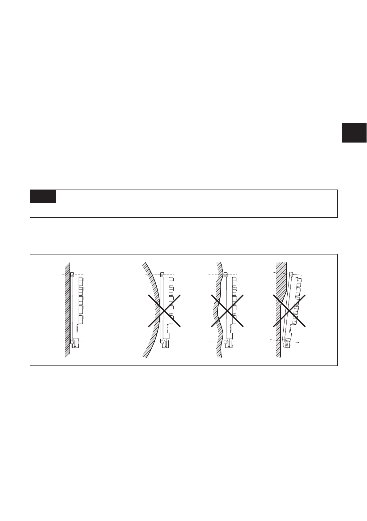
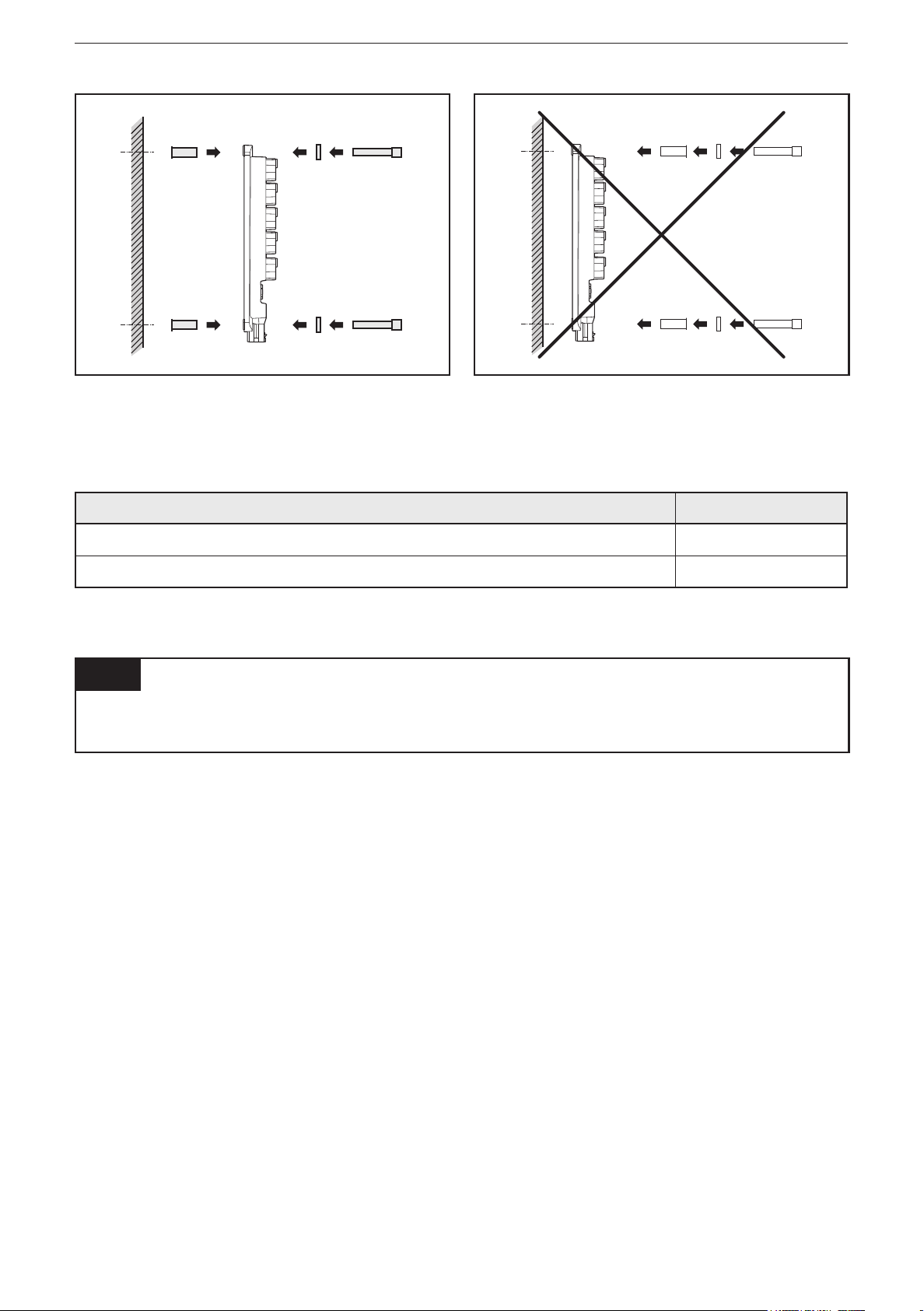
NOTE
The housing must not be exposed to any torsional forces or mechanical stress�
► Mount the device on a flat surface�
► Use compensating elements if there is no flat mounting surface available�
UK
Mounting surface
5.2 Fixing
► Insert the enclosed tubular rivets from the back of the module in the 3 fixing
holes�
► Fix the device using 3 washers and M5 screws�
Tighten the screws alternately�
7
ioControl
Use of the tubular rivets
Tightening torque: 2�0 Nm
Hole dimensions (→ 9 Technical data)
Screws to be used (examples): Standard
Cylinder screws with hexagon socket (M5 x L) DIN EN ISO 4762
Cylinder screws with hexagon socket and low head (M5 x L) DIN 7984
5.3 Cable seal
NOTE
Protection rating IP 65 / IP 67 is only guaranteed if all ports are sealed by means
of connectors or dummy plugs�
8

ioControl
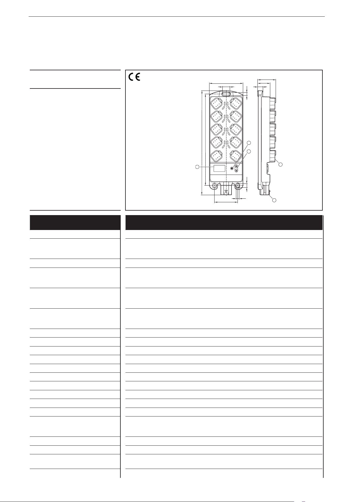
Original Scale Drawing (MTD)
1
3
5
6
7
2
4
878
9
10
11
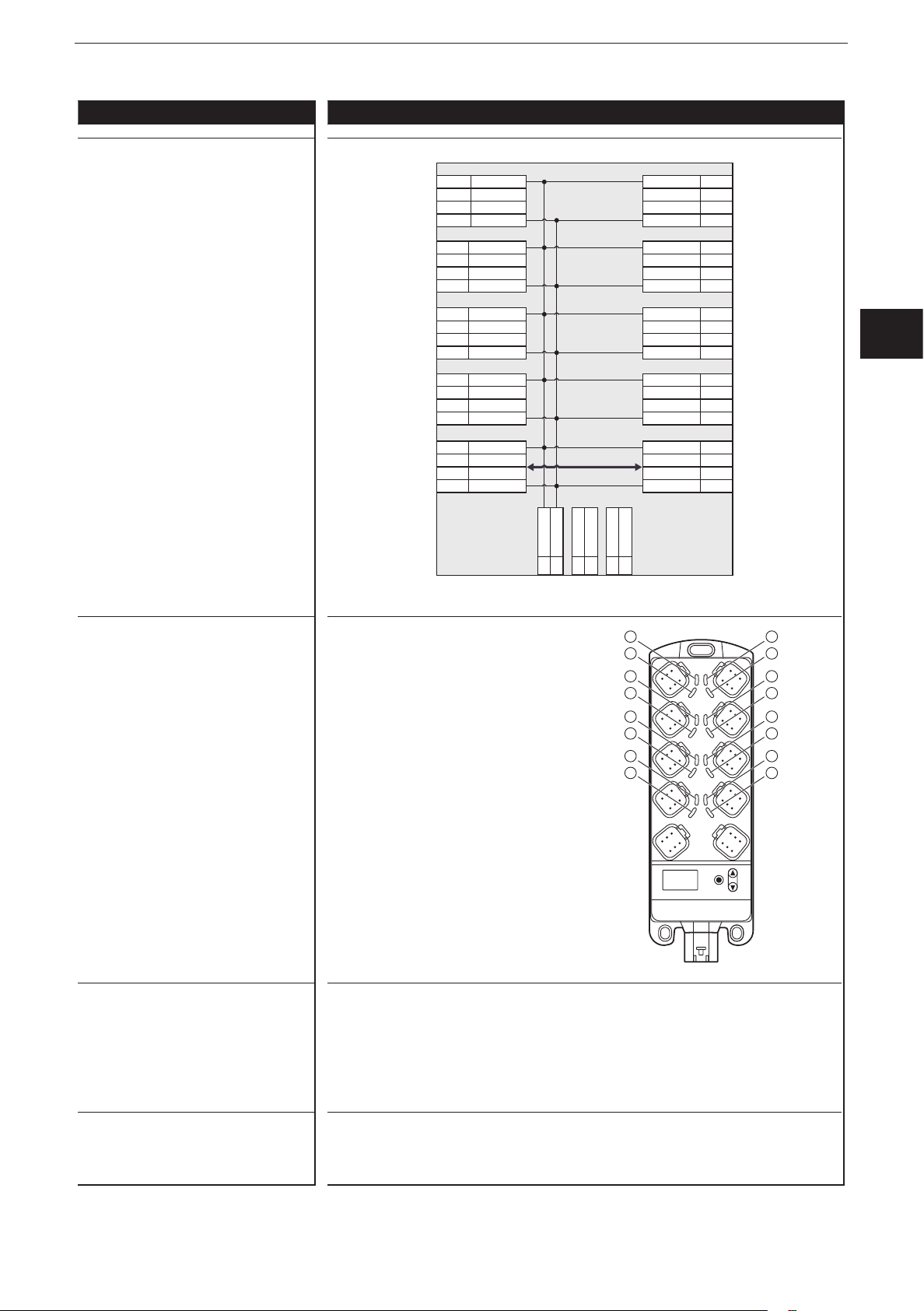
6 Electrical connection
6.1 General electrical connection
The supply cables and the CAN2 interface are connected via the X1 connector
on the bottom of the device� The inputs/outputs, the CAN1 interface and the CAN
supply are connected via the Deutsch connectors on the front side of the housing�
Wiring (→ 9 Technical data)
1: Connector 8
2: Connector 6
3: Connector 4
4: Connection 2
Connector area (here e�g� CR0403)
5: CAN1 OUT
6: X1 - Connection cable plug
7: CAN1 IN
8: Connector 1
9: Connector 3
10: Connector 5
11: Connector 7
9
UK
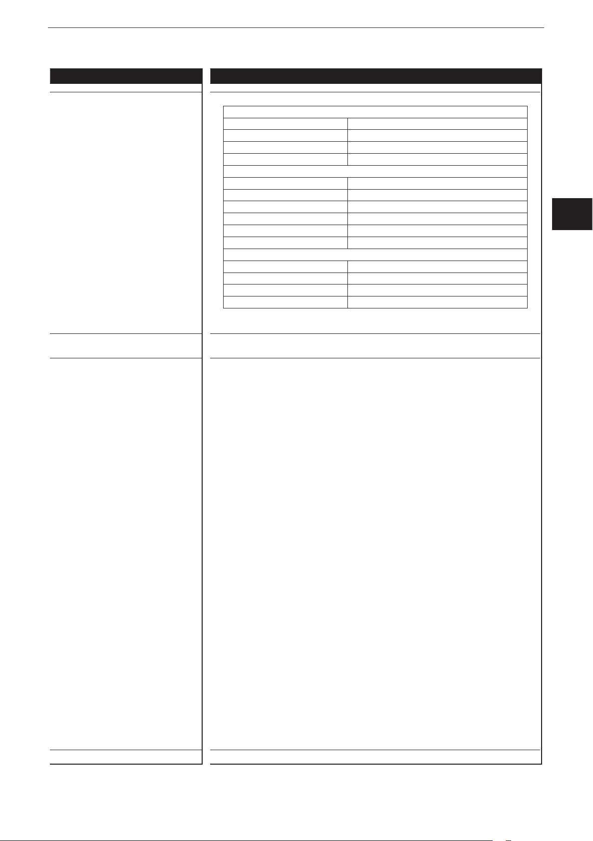
Connector CR2050 CR2051 CR2052 Number
of poles
1 IN00 / IN08 OUT00 / OUT08 IN00 / IN04 6
2 IN01 / IN09 OUT01 / OUT09 OUT00 / OUT04 6
3 IN02 / IN10 OUT02 / OUT10 IN01 / IN05 6
4 IN03 / IN11 OUT03 / OUT11 OUT01 / OUT05 6
5 IN04 / IN12 OUT04 / OUT12 IN02 / IN06 6
6 IN05 / IN13 OUT05 / OUT13 OUT02 / OUT06 6
7 IN06 / IN14 OUT06 / OUT14 IN03 / IN07 6
8 IN07 / IN15 OUT07 / OUT15 OUT03 / OUT07 6
CAN1 IN CAN1 interface 6
CAN1 OUT CAN1 interface (e�g� for looping through) 6
X1 Supply voltage and CAN2 interface 6
NOTE
Wrong connection may cause damage to the device�
► Observe the safety instructions (→ 2.3 Electrical connection)�
9

ioControl
► Basically all supply and signal cables must be laid separately�
► Lay supply and signal cables away from the device using the shortest possible
route�
► All connected cables must be provided with a strain relief max� 400 mm behind
the cable entry�
► Cover unused terminals with dummy plugs / seals�
6.2 Connection accessories
Information about the available accessories at www�ifm�com
6.3 Frequency inputs
CR2050 / CR2052:
► Operate frequency inputs with screened cables so that useful signals are not
affected by external interference�
6.4 Reverse polarity protection
Reverse polarity protection of the operating voltage is only ensured in case of
operation on an on-board system in connection with a fuse� In case of operation
via a power supply, there is no reverse polarity protection of the operating voltage�
CR2051: There is no reverse polarity protection of the CAN supply voltage, as this
voltage is not used within the device�
6.5 Supply of the signal generators at the inputs
CR2050 / CR2052:
► Use sensor voltage VBBS of the corresponding connector as supply voltage for
the signal generators at the inputs (e�g� switches or sensors)�
► If the input (switch or sensor) is supplied via an external voltage, protect this
voltage with max� 3 A�
6.6 Fuses
► The individual electric circuits must be protected in order to protect the whole
system�
Designation Potential Connector: Pin Fuse
VBBSSupply sensors/module 8���32 V DC AMP connector:
Pin 4
VBB1Supply outputs
CR2050: not available
CR2051: OUT00, 02, 04, 06, 08, 10, 12, 14
CR2052: not available
VBB2Supply outputs
CR2050: not available
CR2051: OUT01, 03, 05, 07, 09, 11, 13, 15
CR2052: OUT00���07
10
8���32 V DC AMP connector:
Pin 4
8���32 V DC AMP connector:
Pin 6
CR2050: 3 A
CR2052: 3 A
CR2050: CR2051: ≤ 25 A
CR2052: -
CR2050: -
CR2051: ≤ 25 A
CR2052: ≤ 25 A

Designation Potential Connector: Pin Fuse
Supply
3 A
Supply
ioControl
V
CAN
Optional supply CAN1 interface
CR2050: connected to VBBS
CR2051: no connection to VBBS
CR2052: connected to VBB
S
8���32 V DC CAN IN: Pins 3+4
CR2050: CR2051: 3 A
CR2052: -
► Connect the ground pins belonging to the supply voltages (GND1, GND2, if
appl� GND
) to the common ground�
CAN
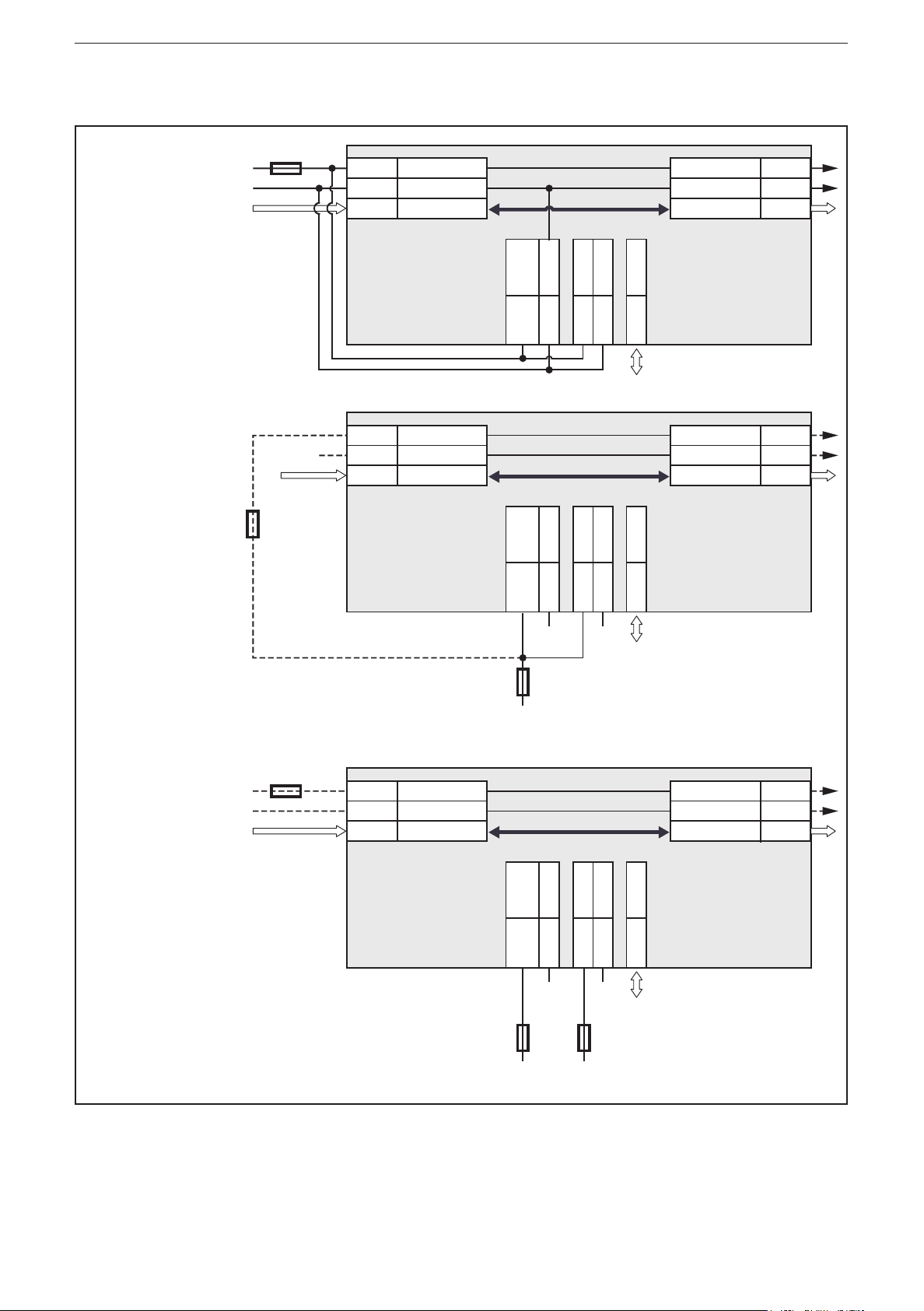
6.7 Examples for connection types
6.7.1 CR2050
Example 1
CAN loop,
supply via
CAN IN
03/04 V
01/06 GND
02/05
CAN
CAN
CAN1
CAN IN CAN OUT
*
S
VBB
GND1n.c.
CR2050
01
04
06
03 n.c.
02/05 CAN2
CAN
V
CAN
GND
CAN1
* Load-Dump
Protection
UK
03/04
01/06
02/05
Example 2
Supply via
connectorX1
n.c. n.c.
03/04 V
01/06 GND
02/05
CAN
CAN
CAN1
CAN IN CAN OUT
*
S
VBB
GND1n.c.
GND
CAN1
CR2050
01
04
3 A
06
n.c.
03 n.c.
02/05 CAN2
CAN
CAN
03/04V
01/06
02/05
* Load-Dump
Protection
11
ioControl
Supply
3 A
Supply
Supply
Supply
6.7.2 CR2051
Example 1
CAN loop, low
load, supply
via CAN IN
Example 2
medium load,
common fuse
**additional
protection
required if
common fuse
> 3 A
3 A**
GND
03/04 V
01/06 GND
02/05
CAN
CAN
GND
CAN1
CAN IN CAN OUT
/
*
S
1
VBB
VBB
GND1VBB2GND
2
CAN2
CR2051
06
03/04 V
CAN
01/06 GND
CAN
04
01
03
02/05
GND
02/05 CAN1
CAN IN CAN OUT
/
*
S
1
VBB
VBB
GND1VBB2GND
2
CAN2
CR2051
06
04
GND
01
GND
03
02/05
CAN
CAN1
CAN
03/04V
01/06
02/05
* Load-Dump
Protection
CAN
CAN1
CAN
03/04V
01/06
02/05
* Load-Dump
Protection
max. 25 A
Supply
Example 3
max. load
3 A
03/04 V
01/06 GND
02/05
CR2051
CAN
CAN
CAN1
CAN IN CAN OUT
/
*
S
1
VBB
VBB
GND1VBB2GND
2
CAN2
CAN
CAN
GND
CAN1
* Load-Dump
03/04V
01/06
02/05
Protection
04
01
03
02/05
06
GND GND
15...25 A
max. 25 A
Protection against overvoltage from the vehicle's on-board system is only ensured
if the connection VBBS/VBB1 is protected with at least 15 A (example 3) or if all
voltages are protected by means of a common fuse (examples 1 and 2)�
12
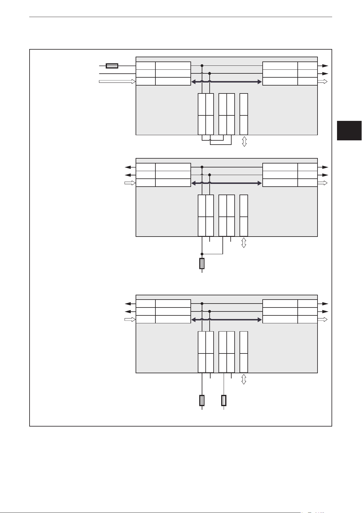
6.7.3 CR2052
Supply
3 A
Supply
Supply
ioControl
Example 1
CAN loop, low
load, supply
via CAN IN
Example 2
low load,
common fuse
03/04 V
01/06 GND
02/05
CAN
CAN
GND
CAN1
CAN IN CAN OUT
S
VBB
1
GND
*
2
VBB
2
CR2052
01
04
03/04 V
01/06 GND
02/05
CAN
CAN
CAN1
CAN IN CAN OUT
S
VBB
1
GND
06
*
2
VBB
03 GND
2
02/05 CAN2
GND
CR2052
01
04
06
03 GND
02/05 CAN2
CAN
V
CAN1
CAN
03/04
01/06
02/05
* Load-Dump
Protection
CAN
V
CAN1
CAN
03/04
01/06
02/05
* Load-Dump
Protection
UK
Example 3
max. load
GND GND
3 A
Supply
03/04 V
01/06 GND
02/05
CAN
CAN
GND
CAN1
CAN IN CAN OUT
S
VBB
1
GND
*
2
VBB
2
CR2052
01
04
GND
3 A
06
03 GND
GND
15...25 A
02/05 CAN2
CAN
V
CAN1
CAN
03/04
01/06
02/05
* Load-Dump
Protection
Protection against overvoltage from the vehicle's on-board system is only ensured
if the connection VBB2 is protected with at least 15 A (example 3) or if all voltages
are protected by means of a common fuse (examples 1 and 2)�
13
ioControl
Original Scale Drawing (MTD)
Original Scale Drawing (MTD)
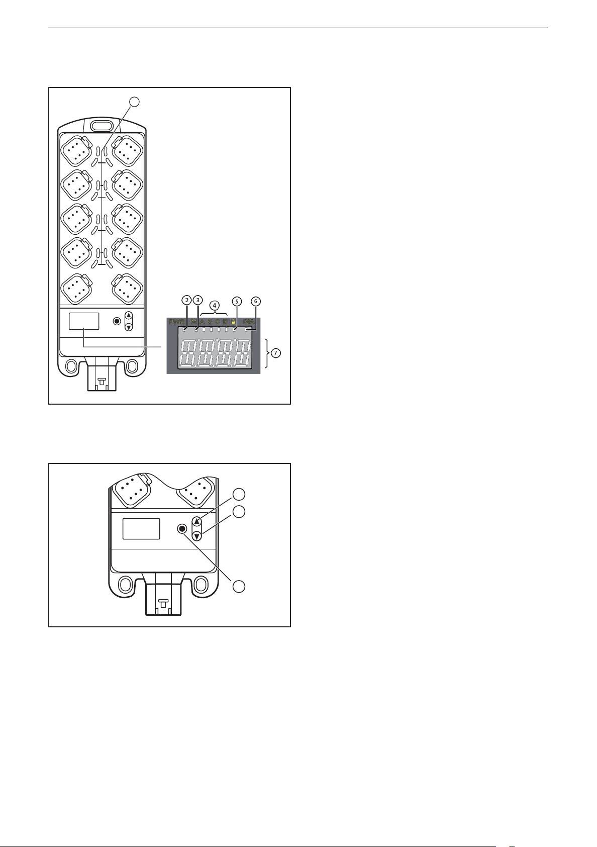
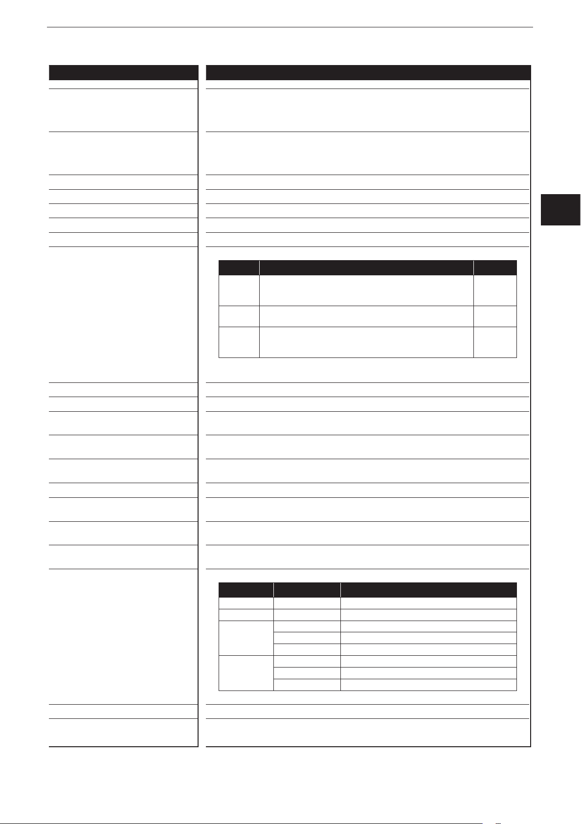
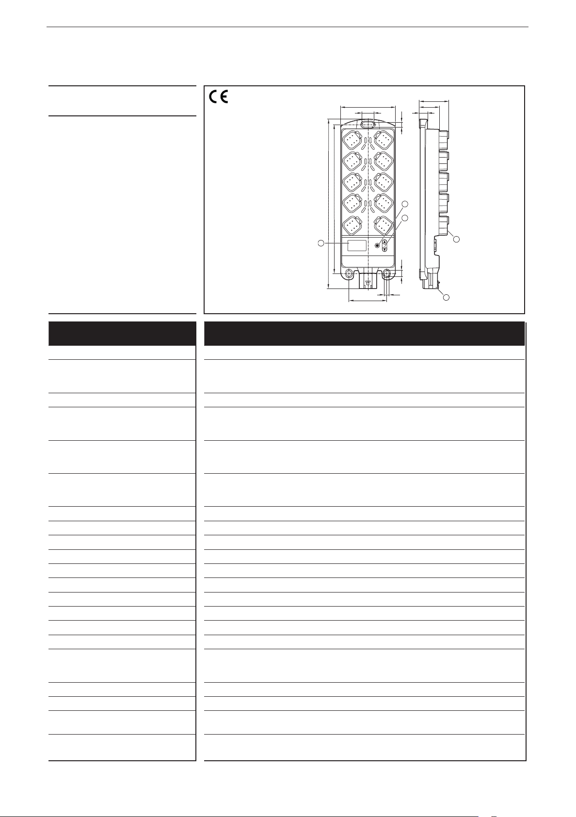
7 Operating and display elements
1
8
7
6
5
4
3
1 2
Indicators
10-segment display (→ 9 Technical data)
1
2
3
1: I/O LEDs (yellow)
2: Power LED (green)
3: Mode LED (green)
4: Application LEDs LED A���LED D (green)
5: Lock LED (green)
6: Diagnostics LED (red)
7: 4-digit 10-segment display
1: UP button
2: DOWN button
3: ENTER button
Operating elements
Pushbutton functions (→ 8.1 I/O module)�
14

7.1 Menu structure
The following description of the menu structure refers to the factory
setting as I/O module� When the device is configured as a controller, the
corresponding menu structure has to be defined (see system manual
ioControl)�
1
ioControl
Node ID
Baud rate
Error code 1
Error code 2
Error code 3
Error code 4
+
>10 s
nodE
BAUD
>10 s
uLoc
+
-123
-123
-123
20
50
100
125
250
500
2
UK
1...125
1: Display mode (→ 8.1.1)
2: Editing mode (→ 8.1.2)
List of parameters: (→ 8.1.3)
800
1000
1
Loc
15

ioControl
7.2 Status indication of the inputs/outputs (I/O LEDs, yellow)
I/O configuration
(see attached object directory)
0 (not used) Off
1 (digital input BL) Off Input signal FALSE
2 (digital output BH) Off Output signal FALSE
3 (voltage input 10 V) Off
4 (PWM output) Off PWM = 0
5 (current-controlled output) Off Current value ≤ 20 mA
6 (voltage input 32 V, ratiometric) Off
7 (current input 20 mA) Off
LED status Description
On Input signal TRUE
On Output signal TRUE
On PWM > 0
On Current value ≤ 20 mA
2 Hz Fault at the input
9 (voltage input 32 V) Off
10 (digital input BL) Off Input signal FALSE
On Input signal TRUE
11 (digital input BL, mit Diagnose) Off Input signal FALSE
On Input signal TRUE
2 Hz Fault at the input
12 (digital input BH) Off Input signal FALSE
On Input signal TRUE
14 (frequency input) Off
2 Hz Fault at the input
15 (digital output BH, with diagnostics) Off Output signal FALSE
On Output signal TRUE
2 Hz Fault at the output
16 (digital output BH, with diagnostics,
short-circuit proof and overload protected)
Off Output signal FALSE
On Output signal TRUE
2 Hz Fault at the output
18 (resistor input) Off
20 (interval measurement) Off
16
2 Hz Fault at the input
2 Hz Fault at the input

ioControl
8 Set-up
8.1 I/O module
On delivery the device is configured as I/O module�
After power on the 10-segment display indicates the article number of the device,
followed by the set node ID�
8.1.1 Display mode
If the green Lock LED is on, the device is in display mode� The device can only
indicate the set node ID and baud rate and, if appl�, error messages; parameters
cannot be edited�
► Press the DOWN button�
> The device displays the set baud rate�
► Press the DOWN button�
> The device displays error code 1, if applicable�
► Press the DOWN button again�
> Every time the DOWN button is pressed, the device displays another error
code, if applicable�
► Use the UP button to go back�
Max� 4 different error codes can occur and be displayed:
Error code Description
SH Short circuit to GND
UK
OP Wire break
oL Excessive current
Comm Communication error
If no button is activated for 10 s, the device displays the set node ID�
8.1.2 Parameter setting
► Press UP and DOWN simultaneously for at least 10 s to change to the editing
mode�
> Green Lock LED goes out�
> Parameters can be edited�
> "uLoc" is displayed for 5 s
> "nodE" is displayed
► Press the ENTER button�
> The device displays the set node ID�
17

ioControl
> The 1st digit to be edited flashes�
► Use the UP and DOWN buttons to set the requested value�
► Use the ENTER button to go to the next digit�
> The 2nd digit to be edited flashes�
► Use the UP and DOWN buttons to set the requested value�
► Use the ENTER button to go to the next digit�
> The 3rd digit to be edited flashes�
► Use the UP and DOWN buttons to set the requested value�
► Press the ENTER button�
> The set node ID is confirmed�
> "nodE" is displayed
► Press the DOWN button�
> "BAUD" is displayed
► Press the ENTER button�
> The device displays the set baud rate�
► Use the UP and DOWN buttons to set the requested value�
► Press the ENTER button�
> The set baud rate is confirmed�
Changes of the parameters are only applied after a reset of the device�
Exit the editing mode:
► Press UP and DOWN simultaneously for at least 10 s�
> Green Lock LED on�
> Parameters cannot be edited�
> "Loc" is displayed for 5 s, then the set node ID is displayed
If no button is activated for 30 s, the device automatically finishes the editing
mode�
8.1.3 List of parameters
Parameters Function Value range Default value
nodE Node ID of the device 1���125 125
BAUD Baud rate 20, 50, 100, 125, 250, 500, 800, 1000 250 kBit/s
18
ioControl
8.2 Controller
The device can be configured as a controller� The existing menu structure and the
properties as I/O module will be lost�
8.2.1 Programming
The user can easily create the application software by means of the IEC 61131-3
compliant programming system CODESYS 2�3�
WARNING
The user is responsible for the safe function of the application programs which
he created himself� If necessary, he must additionally carry out an approval
by corresponding supervisory and test organisations according to the national
regulations�
UK
For notes on the setting of the CAN ID and the baud rate when used as
CANopen slave, refer to the system manual�
8.3 Required documentation
In addition to the CODESYS programming system, the following documents are
required for programming and set-up of the device:
● Programming manual CODESYS V2�3
(alternatively as online help)
● System manual ioControl
(alternatively as online help)
The manuals can be downloaded from the internet:
www�ifm�com
8.4 Required hardware
If used as mobile controller a CAN interface for connection to a PC or notebook is
required to load the application program to the device�
Example:
● CAN/RS232 USB interface CANfox
● Adapter cable for CANfox
You can find more information about the available accessories at:
www�ifm�com
19
ioControl
Control systems
Original Scale Drawing (MTD)
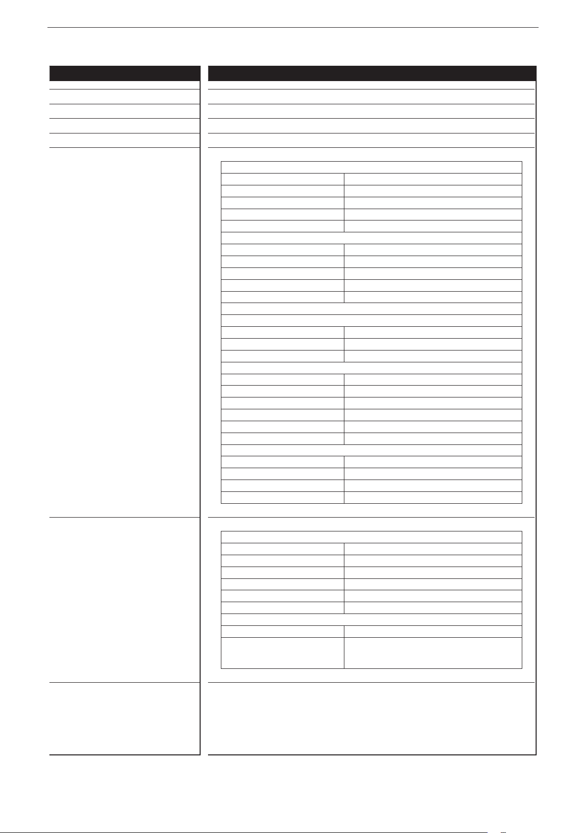
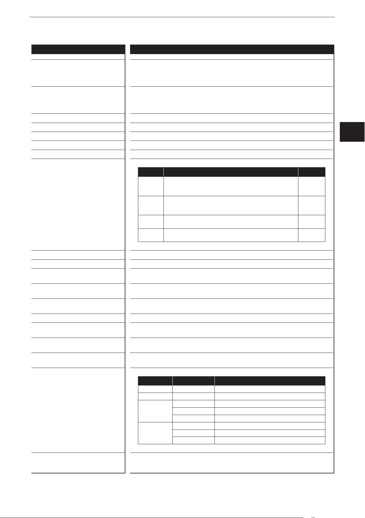
9 Technical data
9.1 CR2050
CR2050
I/O module
digital and analogue
for R360 system
CANopen slave
Mobile controller
Programming
to IEC 61131-3
16 inputs
2 CAN interfaces
8���32 V DC
1: ENTER button
76
17
8
7
6
5
4
3
205,5
234,2
3
1 2
40,5
27,4
11
6,9
1
2
4
8,7
2: UP/DOWN buttons
3: 10-segment display
4: DEUTSCH connector
6,9
52
5
5: AMP connector
Technical data Modular control system
Usable as CANopen slave or intelligent I/O module
Mechanical data
Housing Housing: PA6/6�6
Display: PA
Pushbuttons: silicone
Dimensions (H x W x D) 234 x 76 x 40�5 mm (without tubular rivet)
Installation Fixing by means of 3 M5 screws to DIN EN ISO 4762 or DIN 7984, 3 tubular
rivets to DIN 7340 and 3 washers to DIN EN ISO 7092 (tubular rivets and
washers are supplied)
Connection Supply: MCP2�8 6 poles for connector TE-AMP 1745078-1
Inputs/outputs: Deutsch DT04-6S 6 poles
Contacts: AMP: CuFe tin-plated; Deutsch: CuZn, gold-plated
Inputs
CAN1 interface
Operating voltage, CAN2
8 x 6 poles
2 x 6 poles
1 x 6-poles
Protection rating IP 65 and IP 67 (all connectors inserted)
Operating/storage temperature -40���85° C / -40���85° C
Max� perm� relative humidity 90%, non condensing
Max� height above sea level 2000 m
Pollution degree 2
Weight 500 g
Electrical data
Operating voltage 8���32 V DC
Current consumption 100 mA (at 24 V DC) / 185 mA (at 12 V DC) / max� 300 mA
Overvoltage
Undervoltage detection
Undervoltage shutdown
36 V for t ≤ 10 s
≤ 7.8 V
if U
B
if U
≤ 7.0 V
B
Processor Freescale PowerPC, 50 MHz
Memory (total) 592 Kbytes RAM / 1536 Kbytes Flash / 1 Kbyte FRAM
Memory allocation See system manual ioControl and
www�ifm�com
20
CR2050 Technical data
Control systems
Device monitoring Undervoltage monitoring
Watchdog function
Checksum test for program and system
Excess temperature monitoring
CAN interfaces 1 and 2
Baud rate
Communication protocol
20 Kbits/s…1 Mbits/s (default CAN1: 250 Kbits/s, CAN2: 250 Kbits/s)
CANopen, CiA DS 301 version 4, CiA DS 401 version 1�4
CAN interface 2�0 A/B, ISO 11898
or SAE J 1939 or free protocol
Software/Programming
Programming system CODESYS version 2�3 (IEC 61131-3)
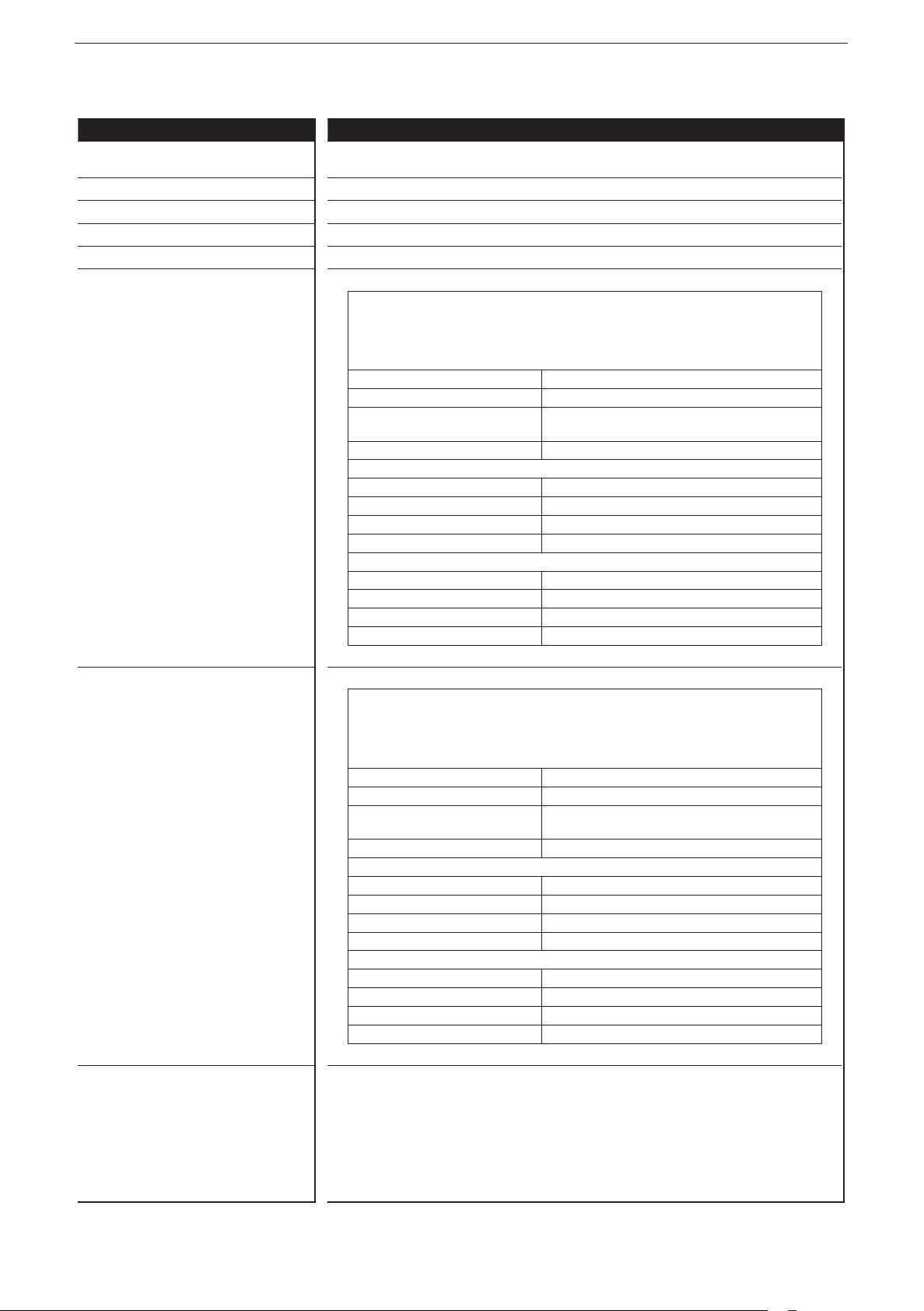
Inputs 16 (confi gurable)
Confi gurations
Number Description
8 digital for positive / negative sensor signals
analogue (0…10/32 V DC, 0���20 mA, ratiometric)
ioControl
B
L/BH
A
UK
4 digital for positive sensor signals
resistance measurement (0.016...30 kΩ)
4 digital for positive sensor signals
digital for negative sensor signals*
frequency (≤ 30 kHz)
* not available in the I/O module (CANopen slave)
Indicators
I/O LEDs 16 x LED orange
(default setting: status indication of the corresponding input)
Power LED (PWR) LED green
(default setting: indication of the system status)
Mode LED (M) LED green
(default setting: indicates that the node ID is displayed)
Application LEDs (A���D) 4 x LED green
Lock LED (lock symbol) 1 x LED green
(default setting: locking of the set parameters)
Diagnostics LED (DIA) 1 x LED red
(default setting: indication of an error)
Display 4-digit 10-segment display (two colours: red/green)
(default setting: indication of the baud rate or the node ID)
Operating states when used as mobile
controller
LED State Description
– Permanently off No operating voltage
PWR + DIA 1 x on Initialisation or reset checks
PWR 5 Hz No operating system loaded
2 Hz Application running (RUN)
Permanently on Application stopped (STOP)
DIA 10 Hz Application stopped (STOP with error)
5 Hz Application stopped due to undervoltage
Permanently on System error (fatal error)
B
L
R
B
L
B
H
FRQ
ifm electronic gmbh • Friedrichstraße 1 • 45128 Essen
We reserve the right to make technical alterations without prior notice! 20 April 2018CR2050 / page 2
21
ioControl
Control systems
CR2050 Technical data
Operating elements
Pushbuttons ENTER, UP, DOWN
Pushbuttons (default setting) Setting of the CAN ID / baud rate
Input characteristics
Analogue inputs (B
IN00 - Connection 1, Pin 5
IN01 - Connection 2, Pin 5
IN02 - Connection 3, Pin 5
IN03 - Connection 4, Pin 5
IN04 - Connection 5, Pin 5
IN05 - Connection 6, Pin 5
IN06 - Connection 7, Pin 5
IN07 - Connection 8, Pin 5
can be confi gured as...
, BH, A)
L
● Voltage inputs
Input voltage 0���10 V or 0���32 V
Resolution 12 bits
Accuracy ± 1% FS
Input resistance 65.6 kΩ (0...10 V), 50.7 kΩ (0...32 V)
Input frequency ≤ 500 Hz
● Current inputs, with diagnostic capability
Input current 0 … 20 mA
Resolution 12 bits
Accuracy ± 1% FS
Input resistance 400 Ω
Input frequency ≤ 500 Hz
At a current of > 23 mA the input is switched to the voltage input!
● Voltage inputs, 0���32 V, ratiometric
Function (U
÷ UB) x 1000 ‰
IN
Value range 0���1000 ‰
Input resistance 50.7 kΩ
● Binary voltage inputs for positive sensor signals
Switch-on level
Switch-off level < 0�3 U
> 0�7 U
B
B
Input resistance 3.2 kΩ
Input frequency 50 Hz
Diagnostics wire break
> 0�95 U
B
Diagnostics short circuit < 1 V
● Binary voltage inputs for negative sensor signals
Switch-on level
Switch-off level < 0�3 U
> 0�7 U
B
B
Input resistance 3.2 kΩ
Input frequency 50 Hz
Digital inputs (B
L
, R)
IN08 - Connection 1, Pin 2
IN10 - Connection 3, Pin 2
IN12 - Connection 5, Pin 2
IN14 - Connection 7, Pin 2
can be confi gured as...
ifm electronic gmbh • Friedrichstraße 1 • 45128 Essen
● Binary voltage inputs for positive sensor signals
Switch-on level
Switch-off level < 0�3 U
> 0�7 U
B
B
Input resistance 3.2 kΩ
Input frequency 50 Hz
Diagnostics wire break
> 0�95 U
B
Diagnostics short circuit < 1 V
● Resistor input
Measuring range 0.016…30 kΩ
Accuracy ± 2% FS: 16 Ω...3 kΩ
± 5 % FS: 3...15 kΩ
± 10 % FS: 15...30 kΩ
We reserve the right to make technical alterations without prior notice! 20 April 2018CR2050 / page 3
22
CR2050 Technical data
Control systems
Frequency inputs (BL, BH, FRQ)
IN09 - Connection 2, Pin 2
IN11 - Connection 4, Pin 2
IN13 - Connection 6, Pin 2
IN15 - Connection 8, Pin 2
can be confi gured as…
● Frequency inputs
Input resistance 3.2 kΩ
Input frequency ≤ 30 kHz
Switch-on level
> 0�7 U
Switch-off level < 0�3 U
B
B
● Binary voltage inputs for positive sensor signals
Switch-on level
Switch-off level < 0�3 U
> 0�7 U
B
B
Input resistance 3.2 kΩ
Input frequency 50 Hz
Diagnostics wire break*
> 0�95 U
B
Diagnostics short circuit* < 1 V
● Binary voltage inputs for negative sensor signals*
Switch-on level
Switch-off level < 0�3 U
> 0�7 U
B
B
Input resistance 3.2 kΩ
Input frequency 50 Hz
* not available in the I/O module (CANopen slave)
ioControl
UK
Max� total current of the CAN supply +
sensor supplies V
CAN
+ VBB
S
1�5 A
ifm electronic gmbh • Friedrichstraße 1 • 45128 Essen
We reserve the right to make technical alterations without prior notice! 20 April 2018CR2050 / page 4
23

ioControl
Control systems
CR2050 Technical data
Test standards and regulations
CE mark EN 61000-6-2 Electromagnetic compatibility (EMC)
EN 61000-6-4 Electromagnetic compatibility (EMC)
E1 marking*
Climatic tests EN 60068-2-30 Damp heat, cyclic
Mechanical tests ISO 16750-3 Test VII; Vibration, random
Chemical resistance ISO 16750-5:2010 AA, AB, BA, BD, CC, DB, DC, DD
UN/ECE-R10 Radiation of interference
ISO 7637-2 Pulse 1, severity level: IV; function state C
EN 60068-2-78 Damp heat, constant
EN 60068-2-52 Salt spray test
EN 60068-2-6 Vibration, sinusoidal
ISO 16750-3 Bump
Noise immunity
Radiation of interference
Immunity with 100 V/m
Pulse 2a, severity level: IV; function state A
Pulse 2b, severity level: IV; function state C
Pulse 3a, severity level: IV; function state A
Pulse 3b, severity level: IV; function state A
Pulse 4, severity level: IV; function state B
Pulse 5, severity level: III; function state C
(data valid for the 24 V system)
Pulse 4, severity level: III; function state C
(data valid for the 12 V system)
upper temperature 55°C, number of cycles: 6
Test temperature 40°C / 93% RH,
Test duration: 21 days
Severity level 3 (vehicle)
Mounting location vehicle body
10���500 Hz; 0�72 mm/10 g; 10 cycles/axis
30 g/6 ms; 24,000 shocks
Note The EC declaration of conformity and approvals can be found at:
* in preparation
www�ifm�com
ifm electronic gmbh • Friedrichstraße 1 • 45128 Essen
24
We reserve the right to make technical alterations without prior notice! 20 April 2018CR2050 / page 5
CR2050 Technical data
Control systems
Original Scale Drawing (MTD)
P_MZ_e100_0092
Wiring
03/04 VBB
02
05
Con. 7
01/06 GND
S
IN14
IN06
1
VBB
IN15
IN07
GND
ioControl
S
03/04
02
05
01/06
Con. 8
1
LED assignment
1: LED IN15
2: LED IN07
3: LED IN13
4: LED IN05
5: LED IN11
6: LED IN03
7: LED IN09
8: LED IN01
9: LED IN08
10: LED IN00
11: LED IN10
12: LED IN02
13: LED IN12
14: LED IN04
15: LED IN14
16: LED IN06
03/04 VBB
02
05
Con. 5
01/06 GND
03/04 VBB
02
05
Con. 3
01/06 GND
03/04 VBB
02
05
Con. 1
01/06 GND
03/04 V
02
05
CAN IN
01/06 GND
CR2050
S
IN12
IN04
S
IN10
IN02
S
IN08
IN00
CAN
CAN1_H
CAN1_L
CAN
S
03/04
VBB
IN13
02 CAN2_L
05 CAN2_H
16
15
14
13
12
11
10
9
IN05
GND
VBB
IN11
IN03
GND
VBB
IN09
IN01
GND
CAN
V
CAN1_H
CAN1_L
GND
* Load-Dump
Protection
1
1
1
*
S
VBB
GND1n.c.
01
04
06
03 n.c.
X1
CAN
02
05
01/06
03/04
01/06
03/04
01/06
03/04
01/06
8
6
4
02
05
02
05
02
05
Con. 6
Con. 4
Con. 2
CAN OUT
1
2
3
4
5
6
7
8
UK
1
S
1
S
1
7
5
3
1 2
Abbreviations A
ifm electronic gmbh • Friedrichstraße 1 • 45128 Essen
We reserve the right to make technical alterations without prior notice! 20 April 2018CR2050 / page 6
B
H
B
L
FRQ
R
VBB
V
CAN
Analogue
Binary high side
Binary low side
Frequency / pulse input
Resistor input
Supply sensors/module
S
Supply CAN connector
25
ioControl
Control systems
Original Scale Drawing (MTD)
9.2 CR2051
CR2051
I/O module
digital and analogue
for R360 system
CANopen slave
Mobile controller
Programming
to IEC 61131-3
16 outputs
2 CAN interfaces
8���32 V DC
1: ENTER button
76
17
8
7
6
5
4
3
205,5
234,2
3
1 2
40,5
27,4
11
6,9
1
2
4
8,7
2: UP/DOWN buttons
3: 10-segment display
4: DEUTSCH connector
6,9
52
5
5: AMP connector
Technical data Modular control system
Usable as CANopen slave or intelligent I/O module
Mechanical data
Housing Housing: PA6/6�6
Display: PA
Pushbuttons: silicone
Dimensions (H x W x D) 234 x 76 x 40�5 mm (without tubular rivet)
Installation Fixing by means of 3 M5 screws to DIN EN ISO 4762 or DIN 7984, 3 tubular
rivets to DIN 7340 and 3 washers to DIN EN ISO 7092 (tubular rivets and
washers are supplied)
Connection Supply: MCP2�8 6 poles for connector TE-AMP 1745078-1
Inputs/outputs: Deutsch DT04-6S 6 poles
Contacts: AMP: CuFe tin-plated; Deutsch: CuZn, gold-plated
Inputs
CAN1 interface
Operating voltage, CAN2
8 x 6 poles
2 x 6 poles
1 x 6-poles
Protection rating IP 65 and IP 67 (all connectors inserted)
Operating/storage temperature -40���85° C / -40���85° C
Max� perm� relative humidity 90%, non condensing
Max� height above sea level 2000 m
Pollution degree 2
Weight 500 g
Electrical data
Operating voltage 8���32 V DC
Current consumption 104 mA (at 24 V DC) / 185 mA (at 12 V DC) / max� 300 mA
Overvoltage
Undervoltage detection
Undervoltage shutdown
36 V for t ≤ 10 s
≤ 7.8 V
if U
B
if U
≤ 7.0 V
B
Processor Freescale PowerPC, 50 MHz
Memory (total) 592 Kbytes RAM / 1536 Kbytes Flash / 1 Kbyte FRAM
Memory allocation See system manual ioControl and
www�ifm�com
ifm electronic gmbh • Friedrichstraße 1 • 45128 Essen
We reserve the right to make technical alterations without prior notice! 15 Aug 2017CR2051 / page 1
26
CR2051 Technical data
Control systems
Device monitoring Undervoltage monitoring
Watchdog function
Checksum test for program and system
Excess temperature monitoring
CAN interfaces 1 and 2
Baud rate
Communication protocol
20 Kbits/s…1 Mbits/s (default CAN1: 250 Kbits/s, CAN2: 250 kBit/s)
CANopen, CiA DS 301 version 4, CiA DS 401 version 1�4
CAN interface 2�0 A/B, ISO 11898
or SAE J 1939 or free protocol
Software/Programming
Programming system CODESYS version 2�3 (IEC 61131-3)
Outputs 16 (confi gurable)
Confi gurations
Number Description
4 positive-switching (high side), 4 A, diagnostics
PWM output (20…250 Hz), 4A, diagnostics
current-controlled 0�02…4 A
4 positive-switching (high side), 2�5 A, diagnostics
PWM output (20…250 Hz), 2�5A, diagnostics
current-controlled 0�02…2�5 A
4 positive-switching (high side), 4 A, diagnostics
PWM output (20…250 Hz), 4A
4 positive-switching (high side), 2�5 A, diagnostics
PWM output (20…250 Hz), 2�5A
ioControl
B
H
PWM
PWM
I
B
H
PWM
PWM
I
B
H
PWM
B
H
PWM
UK
Indicators
I/O LEDs 16 x LED orange
(default setting: status indication of the corresponding output)
Power LED (PWR) LED green
(default setting: indication of the system status)
Mode LED (M) LED green
(default setting: indicates that the node ID is displayed)
Application LEDs (A���D) 4 x LED green
Lock LED (lock symbol) 1 x LED green
(default setting: locking of the set parameters)
Diagnostics LED (DIA) 1 x LED red
(default setting: indication of an error)
Display 4-digit 10-segment display (two colours: red/green)
(default setting: indication of the baud rate or the node ID)
Operating states when used as mobile
controller
LED State Description
– Permanently off No operating voltage
PWR + DIA 1 x on Initialisation or reset checks
PWR 5 Hz No operating system loaded
2 Hz Application running (RUN)
Permanently on Application stopped (STOP)
DIA 10 Hz Application stopped (STOP with error)
5 Hz Application stopped due to undervoltage
Permanently on System error (fatal error)
ifm electronic gmbh • Friedrichstraße 1 • 45128 Essen
We reserve the right to make technical alterations without prior notice!
CR2051 / page 2
15 Aug 2017
27
ioControl
Control systems
CR2051 Technical data
Operating elements
Pushbuttons ENTER, UP, DOWN
Pushbuttons (default setting) Setting of the CAN ID / baud rate
Output characteristics
Digital outputs (B
OUT00 - Connection 1, Pin 5
OUT01 - Connection 2, Pin 5
OUT02 - Connection 3, Pin 5
OUT03 - Connection 4, Pin 5
can be confi gured as ...
, PWM, PWMI)
H
● Semiconductor outputs, positive switching (high side), short-circuit proof and
overload protected�
Diagnosis via current feedback (wire break / overload)
Diagnosis via voltage feedback, pullup resistance can be deactivated (wire
break / short circuit)
Switching voltage 8���32 V
Switching current ≤ 4
Load resistance ≥ 3 Ω (at 12 V DC)
Current measuring range 0,02���6 A
● PWM outputs
Output frequency 20���250 Hz
Pulse/pause ratio 1���1000 ‰
Switching current ≤ 4 A
Current measuring range 0,02���6 A
● Current-controlled output
Output frequency 20���250 Hz
Control range 0,02���4 A
Setting resolution 1 mA
Max� inrush current ≤ 24 A
A
≥ 6 Ω (at 24 V DC)
Digital outputs (B
OUT04 - Connection 5, Pin 5
OUT05 - Connection 6, Pin 5
OUT06 - Connection 7, Pin 5
OUT07 - Connection 8, Pin 5
can be confi gured as…
, PWM, PWMI)
H
● Semiconductor outputs, positive switching (high side), short-circuit proof and
overload protected�
Diagnosis via current feedback (wire break / overload)
Diagnosis via voltage feedback, pullup resistance can be deactivated (wire
break / short circuit)
Switching voltage 8���32 V
Switching current ≤ 2.5
Load resistance ≥ 4.8 Ω (at 12 V DC)
Current measuring range 0,02���4 A
● PWM outputs
Output frequency 20���250 Hz
Pulse/pause ratio 1���1000 ‰
Switching current ≤ 2.5 A
Current measuring range 0,02���4 A
● Current-controlled output
Output frequency 20���250 Hz
Control range 0�02���2�5 A
Setting resolution 1 mA
Max� inrush current ≤ 24 A
A
≥ 9.6 Ω (at 24 V DC)
28
ifm electronic gmbh • Friedrichstraße 1 • 45128 Essen
We reserve the right to make technical alterations without prior notice!
15 Aug 2017
CR2051 / page 4
CR2051 Technical data
Control systems
Digital outputs (BH, PWM)
OUT08 - Connection 1, Pin 2
OUT09 - Connection 2, Pin 2
OUT10 - Connection 3, Pin 2
OUT11 - Connection 4, Pin 2
can be confi gured as...
● Semiconductor outputs, positive switching (high side), short-circuit proof and
overload protected�
Diagnosis via voltage feedback, pullup resistance can be deactivated (wire
break/ short circuit)
Switching voltage 8���32 V
Switching current ≤ 2.5
A
● PWM outputs
Output frequency 20���250 Hz
Pulse/pause ratio 1���1000 ‰
Switching current ≤ 2.5 A
Max� inrush current ≤ 24 A
ioControl
UK
Digital outputs (B
OUT12 - Connection 5, Pin 2
OUT13 - Connection 6, Pin 2
OUT14 - Connection 7, Pin 2
OUT15 - Connection 8, Pin 2
can be confi gured as…
, PWM)
H
● Semiconductor outputs, positive switching (high side), short-circuit proof and
overload protected�
Diagnosis via voltage feedback, pullup resistance can be deactivated (wire
break/ short circuit)
Switching voltage 8���32 V
Switching current ≤ 4
A
● PWM outputs
Output frequency 20���250 Hz
Pulse/pause ratio 1���1000 ‰
Switching current ≤ 4 A
Max� inrush current ≤ 24 A
Free wheel diodes Free wheel diodes for the deactivation of inductive loads are integrated
Overload protection
≤ 5 minutes (at 100% overload)
(valid for all outputs)
Short-circuit protection
≤ 5 minutes
(valid for all inputs and outputs)
Max� total current of the CAN supply
V
CAN
1�5 A
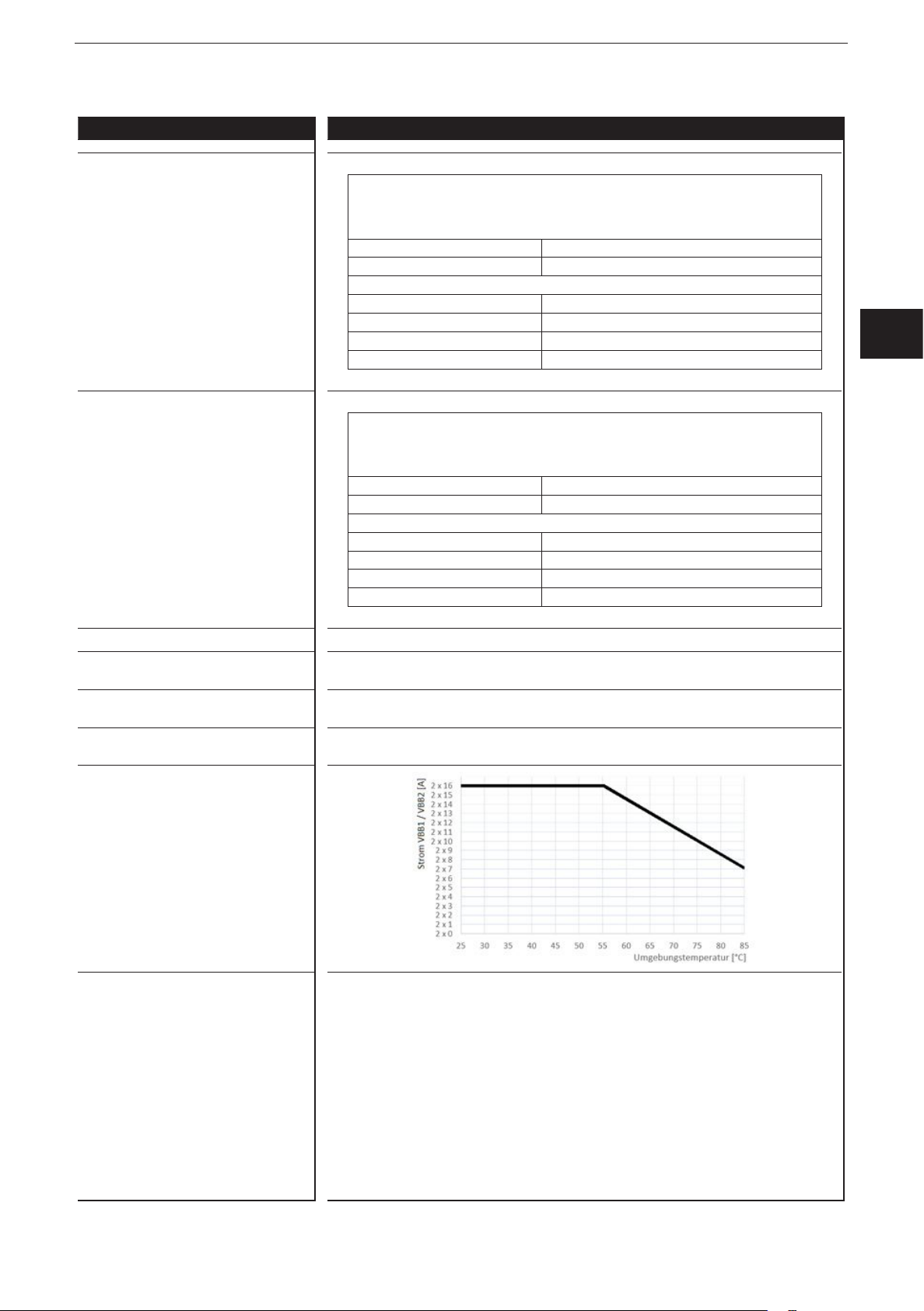
Max� total current of the output supplies
VBB
/ VBB
1
2
29

ioControl
ifm electronic gmbh • Friedrichstraße 1 • 45128 Essen
We reserve the right to make technical alterations without prior notice!
15 Aug 2017
CR2051 / page 5
Control systems
CR2051 Technical data
Test standards and regulations
CE mark EN 61000-6-2 Electromagnetic compatibility (EMC)
EN 61000-6-4 Electromagnetic compatibility (EMC)
E1 marking*
UN/ECE-R10 Radiation of interference
ISO 7637-2 Pulse 1, severity level: IV; function state C
Climatic tests EN 60068-2-30 Damp heat, cyclic
EN 60068-2-78 Damp heat, constant
EN 60068-2-52 Salt spray test
Mechanical tests ISO 16750-3 Test VII; Vibration, random
EN 60068-2-6 Vibration, sinusoidal
ISO 16750-3 Bump
Chemical resistance ISO 16750-5:2010 AA, AB, BA, BD, CC, DB, DC, DD
Noise immunity
Radiation of interference
Immunity with 100 V/m
Pulse 2a, severity level: IV; function state A
Pulse 2b, severity level: IV; function state C
Pulse 3a, severity level: IV; function state A
Pulse 3b, severity level: IV; function state A
Pulse 4, severity level: IV; function state B
Pulse 5, severity level: III; function state C
(data valid for the 24 V system)
Pulse 4, severity level: III; function state C
(data valid for the 12 V system)
upper temperature 55°C, number of cycles: 6
Test temperature 40°C / 93% RH,
Test duration: 21 days
Severity level 3 (vehicle)
Mounting location vehicle body
10���500 Hz; 0�72 mm/10 g; 10 cycles/axis
30 g/6 ms; 24,000 shocks
Note The EC declaration of conformity and approvals can be found at:
www�ifm�com
* in preparation
30
 Loading...