

Page 1
Geräte-Handbuch
Device manual
Ein-/Ausgangs-Modul
Input/output module
CR2013
DEUTSCHENGLISH
7390827/00 09/2010
R
Page 2

Inhalt
Bestimmungsgemäße Verwendung/Funktion Seite 3
Technische Daten Seite 4
Maße Seite 5
Betriebsanzeige (Status-LEDs) Seite 5
Montage Seite 6
Elektrischer Anschluss Seite 6
Inbetriebnahme Seite 7
CoDeSys Steuerungskonfiguration Seite 7
Electronic Data Sheet Seite 7
Wartung, Instandsetzung und Entsorgung Seite 8
Komformitätserklärung Seite 8
Parameter- und EMCY-Objekt-Übersicht Seite 9
Objektverzeichnis
Herstellerspezifische Profile; Index 2000 bis 5FFF Seite 11
Kommunikationsprofile; Index 1000 bis 1FFF Seite 13
Begriffe und Abkürzungen Seite 17
Ein-/Ausgangs-Modul CR2013
2
Sicherheitshinweise
Diese Beschreibung ist Bestandteil des Gerätes. Sie enthält Texte
und Abbildungen zum korrekten Umgang mit dem Modul und
muss vor einer Installation oder dem Einsatz gelesen werden.
Befolgen Sie die Angaben der Dokumentation. Nichtbeachten der Hinweise,
Verwendung außerhalb der nachstehend genannten bestimmungsgemäßen
Verwendung, falsche Installation oder Handhabung können Beeinträchtigungen der Sicherheit von Menschen und Anlagen zur Folge haben.
Das Gerät darf nur von einer Elektrofachkraft eingebaut, angeschlossen und
in Betrieb gesetzt werden.
Schalten Sie das Gerät extern spannungsfrei bevor Sie irgendwelche Arbeiten
an ihm vornehmen. Schalten Sie ggf. auch unabhängig versorgte Ausgangslastkreise ab.
Bei Fehlfunktion des Geräts oder bei Unklarheiten setzen Sie sich bitte mit
dem Hersteller in Verbindung. Eingriffe in das Gerät können schwerwiegende
Beeinträchtigungen der Sicherheit von Menschen und Anlagen zur Folge
haben. Sie sind nicht zulässig und führen zu Haftungs- und Gewährleistungsauschluss.
Page 3

Bestimmungsgemäße Verwendung / Funktion
Das Ein-/Ausgangs-Modul CR2013 dient zur dezentralen CAN-Bus-Anbindung
von Sensoren und Aktoren.
• Das E/A-Modul unterstützt binäre und analoge Ein-/Ausgänge und wird daher
in die Geräteklasse „I/O Modul“ entsprechend CiA DS 401 eingeordnet und
gekennzeichnet.
• Das E/A-Modul ist in der Anordnung der Ein- und Ausgänge konfigurierbar.
• Es sind 1 Server SDO und die 4 Default PDOs gemäß CiA DS 401 eingerichtet.
Das PDO-Mapping kann nicht geändert werden (statisches PDO-Mapping).
Die Default-Identifier sind ensprechend des „Predefined connection set“ vergeben.
• Die COB-IDs der PDOs sowie die Übertragungsart (synch/asynch) der einzelnen
PDO sind konfigurierbar.
Die Übertragungsart wird spannungsausfallsicher gespeichert. Geänderte PDOs
(PDO-linking) werden nicht spannungsausfallsicher gespeichert.
• Das E/A-Modul erwartet ein Synch-Objekt.
Der CAN Identifier des Synchobjektes ist konfigurierbar. Nach einer Änderung
wird der ID automatisch spannungausfallsicher gespeichert.
• Das E/A-Modul unterstützt „Node guarding“.
Die „Guard time“, der „Life time factor“ und der CAN Identifier des Guard
Objektes sind konfigurierbar und werden spannungsausfallsicher gespeichert.
• Das E/A-Modul generiert ein Emergency Objekt. Der COB-ID des EMCY-Objektes ist konfigurierbar.
• Das E/A-Modul speichert die 4 zuletzt aufgetretenen Fehler.
Abgelegt wird der Fehlercode des jeweiligen Emergency Objektes.
• Zusätzlich zum CANopen Fehlerregister ist ein gerätspezifisches Statusregister
eingerichtet, welches die Stati der Ausgangstreiber beinhaltet.
• Das E/A-Modul unterstützt eine Reset-Funktion; d.h. die Belegung der Parameter mit den werkseitigen Default-Werten* nach Aufforderung.
*) Werkseitige Default-Einstellungen siehe „Parameterliste“, Seite 9
DEUTSCH
Ein-/Ausgang-Modul CR2013
3
Page 4

Technische Daten
Ein-/Ausgangs-Modul CR2013
4
Gehäuse
Maße
Geräteanschluss
Betriebstemperatur
Lagertemperatur
Schutzart, Schutzklasse
Betriebsspannung (UB)
Stromaufnahme
Anzeigen
Schnittstelle
Baudrate
Kommunikationsprofil
Geräteklasse
CAN
Binäre Eingänge
Einschaltpegel
Ausschaltpegel
Erfassbare Impulse
ohne Filterfunktion
mit Filterfunktion
Analoge Eingänge
Eingangsspannung
Eingangsimpedanz
Auflösung
Genauigkeit
Sensorversorgung I
max
Binäre Ausgänge
Schaltspannung
Schaltstrom
Überlaststrom
Summenstrom
PWM-Ausgänge
Ausgangsfrequenz
PWM-Tastverhältnis
Auflösung
8-fach Verteiler-Gehäuse aus Polyamid (PA), mit
eingebauter Elektronik vollvergossen
152mm x 60mm x 22mm ( L x B x H )
PUR/PVC-Kabel 2 m
2 x 1,5 mm
2
(Betriebsspannung) / 3 x 0,5 mm2(CAN-Bus)
M12-Steckverbinder für Ein- / Ausgänge
-25...85 °C
-40...90 °C
IP 67 III
10...30 V DC, SELV
≤ 100 mA, ohne externe Last
LED grün: Run-LED
LED rot: Diagnose-LED
LED gelb: Status des Eingangs / Ausgangs
CAN Interface - ISO 11898
10 kbit/s - 1 Mbit/s
CANopen
I /O-Modul entspr. CiA DS401, CiA DS301 V3.0
Full-CAN 2.0
Buchsen 1, 3, 5, 7
0,4...0,7 U
B
0,2...0,24 U
B
ti ≥ 2 ms (typ.)
ti ≥ 20 ms (typ.)
Buchsen 2, 4, 6, 8
0...10 V DC
≥ 50 kΩ
10 Bit
≤ ± 1,0% FS
Die Ausgangsimpedanz der Analogquelle sollte maximal
10 kΩ betragen
300 mA
Buchsen 2, 4, 6, 8
Halbleiterausgänge, kurzschluss- / überlastfest; diagnosefähig
10...30 V DC
max. 4 A
(Lasten < 900 mA können das Fehlersignal “Leitungsbruch”
erzeugen)
4,4 A
16 A
Buchsen 2, 4, 6, 8
20...200 Hz
1...100%
1%
Bei Konfiguration als PWM-Ausgang wird die
Status-LED bei PWM-Werten ≥ 1% statisch gesetzt.
Es ist keine Diagnose möglich
Page 5

Maße
Betriebsanzeigen
DEUTSCH
Ein-/Ausgang-Modul CR2013
5
grün
AUS keine Versorgungsspannung
EIN
Modul im Stand by-Modus
CANopen-Status: PREOPERATIONAL / PREPARED
Ausgänge = AUS; Eingangszustände werden nicht übertragen
rot
AUS Kommunikation ok.
gelb IN EIN Eingang ist EIN
gelb OUT
EIN
Binärer Ausgang: Ausgang ist angesteuert / EIN
Analoger Ausgang: PWM-Sollwert ist größer 1%
blinkend
1 Hz
Ausgangstreiber signalisiert Fehler:
- Kurzschluss / Überlast / keine Last (im Grenzfall Laststrom < 900mA)
- Übertemperatur / Unterspannung / Überspannung
Die LED-Funktion kann gesperrt werden (s. Seite 9, OBV, Index 2002)
EIN
Kommunikation gestört
- NodeGuard-Fehler (wenn NodeGuarding aktiviert ist)
- keine Synch-Objekte (wenn Synch-Überwachung aktiviert ist)
- CANopen-Schnittstelle defekt
blinkend
2 Hz
Modul aktiv
CANopen-Status: OPERATIONAL
Ausgänge werden aktualisiert, Eingangszustände übertragen
ZustandLED-Farbe Beschreibung
152
107
60
8
7
6
5
PWR
4
3
DIA
12
5
M12x1
4,7
18
22
28,5
39
7,5
4,5
Page 6
Montage
Passende Unterlegscheiben verwenden.
Anzugdrehmoment der Befestigungsschrauben: max. 1,8 Nm
Elektrischer Anschluss
Zum Schutz des gesamten Systems (Verkabelung und E/A-Modul) sind die
einzelnen Stromkreise mit max. 16 A abzusichern.
Ein-/Ausgangs-Modul CR2013
6
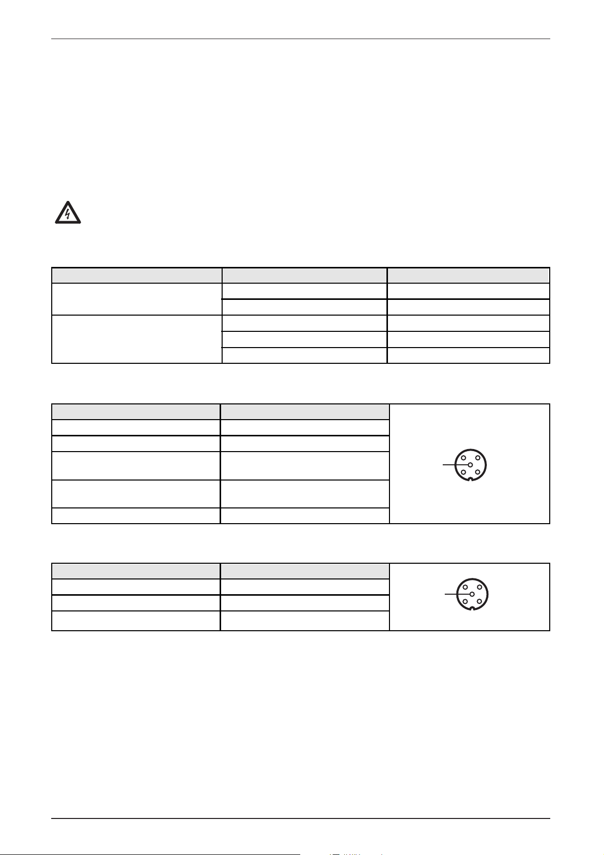
1 Sensorversorgung L+
3 Sensorversorgung L-
4
Signaleingang
(Schalter, Sensor)
2
Signaleingang
(Analogsensor)
5 n. c.
1
34
2
5
Buchsenbelegung (Eingänge)
Adernfarbe
Potential
Betriebsspannung
rot
10 ... 30 V DC
schwarz
GND
CAN-Interface
weiß
CAN_H
blau
CAN_L
grün CAN_GND
M12-Buchse PIN Belegung
4 Schaltausgang L+
3 externe Spannung -
5 n. c.
1
34
2
5
Anschlussbelegung
Buchsenbelegung (Ausgänge)
M12-Buchse PIN Belegung
Page 7
Inbetriebnahme
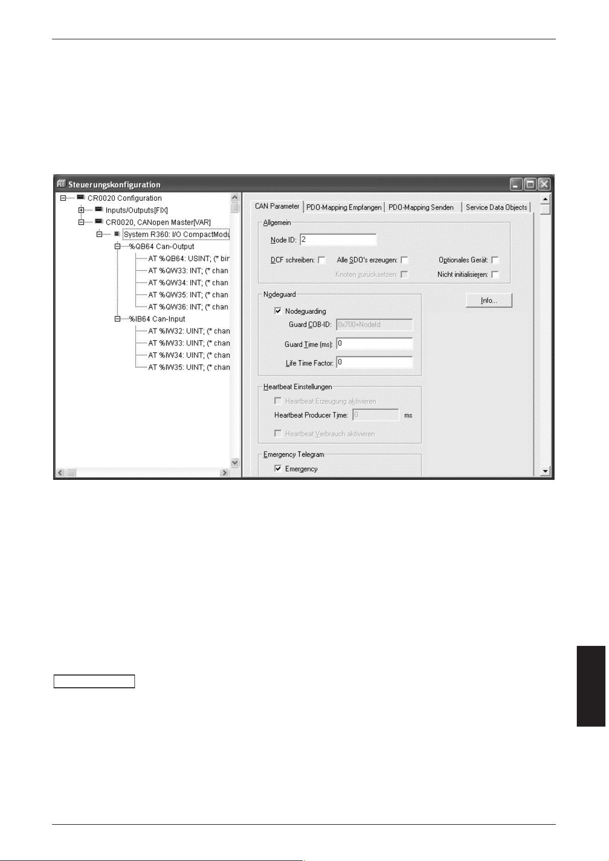
CoDeSys Steuerungskonfiguration
Die Parametrierung der Gerätefunktionen und der CAN-Schnittstelle erfolgt aus
der mit CoDeSys 2.3 programmierten Applikation. Dazu wird das "Electronic
Data Sheet" (EDS) über die CoDeSys Steuerungskonfiguration eingebunden.
CoDeSys Dialog „Steuerungs- und CANopen-Konfiguration“ (Beispiel)
Eine Beschreibung zur Einstellung und Anwendung des Dialogs „Steuerungs- und
CANopen-Konfiguration“ finden Sie im CoDeSys-Handbuch und in der CoDeSysOnlinehilfe.
Electronic Data Sheet
Das EDS beinhaltet die Beschreibung samtlicher Parameter und E/A-Daten des
Gerates in einer durch CANopen definierten Form. Die EDS-Dateien werden von
ifm electronic für alle ifm CANopen Slaves zu Verfügung gestellt.
Die EDS-Dateien sind abrufbar unter:
➔ Datenblatt-Suche ➔ CR2013 ➔ Download/Software*
*) Downloadbereich mit Anmeldung
www.ifm.com
DEUTSCH
Ein-/Ausgang-Modul CR2013
7
Page 8

Wartung, Instandsetzung und Entsorgung
Da innerhalb des Moduls keine vom Anwender zu wartenden Bauteile enthalten
sind, darf das Gehäuse nicht geöffnet werden. Die Instandsetzung des Moduls
darf nur durch den Hersteller durchgeführt werden.
Die Entsorgung muss gemäß den nationalen Umweltvorschriften erfolgen.
Konformitätserklärung
Die EG-Konformitatserklärung ist abrufbar unter:
➔ Datenblatt-Suche ➔ CR2013 ➔ Zulassungen
www.ifm.com
Ein-/Ausgangs-Modul CR2013
8
Page 9

Parameter- und EMCY-Objekt-Übersicht
Über die Funktion „Restore“ (siehe Objektverzeichnis; Index 1011) können die
Parameter (Ausnahme Baudrate und Node-ID) mit den werkseitig hinterlegten
Default-Werten belegt werden. Diese sind dann nach dem nächsten Einschalten
der Versorgungsspannung gültig.
Parameterliste
Life Time Factor 0 wird als 1 interpretiert
Das erste Guardprotokoll wird als “Start Guarding” gewertet, auch wenn zu diesem Zeitpunkt das Guarding nicht aktiviert ist (Guardtime = 0).
DEUTSCH
Ein-/Ausgang-Modul CR2013
9
Node-ID 0x20 (= 32)20F0, 20F1 ja nach Reset
20F2, 20F3 ja nach Reset
1005 ja sofort
1006 ja nach Pre-Op
100C ja sofort
100D ja sofort
100E ja sofort
1014 ja sofort
1400 01 nein sofort
1400 02 ja sofort
1401 01 nein sofort
1401 02 ja sofort
1800 01 nein sofort
1800 02 ja sofort
1801 01 nein sofort
1802 02 ja sofort
2000 ja nach Pre-Op
2001 ja nach Pre-Op
2002 ja sofort
Baudrate 0x03 (= 125 kBit/s)
COB ID Synch Objekt 0x80
Communication Cycle 0 (Off)
Guard Time 0 (Off)
Life Time Factor 0 (Off)
COB ID Guarding 0x700 + Node ID
COB ID EMCY 0x80 + Node ID
COB ID Rec PDO1 0x200 + Node ID
Trans Type Rec PDO1 synchron 1
COB ID Rec PDO2 0x300 + Node ID
Trans Type Rec PDO2 synchron 1
COB ID Trans PDO1 0x180 + Node ID
Trans Type Trans PDO1 nach Änderung
COB ID Trans PDO2 0x280 + Node ID
Trans Type Trans PDO2 synchron 1
I/O Konfiguration binär Ein-/Ausgänge
PWM Frequenz 0x64 (= 100 Hz)
Statusmeldung Ausgänge 0x01 (= EIN)
2003 ja sofortFilterfunktion 0x00 (= AUS)
Herstellerspezifische Profile; Index 2000 bis 5FFF
Kommunikationsprofile; Index 1000 bis 1FFF
Parameter
Defaultwert
(werksseitig
eingestellt)
Ojekt-
verzeichnis
Index
Änderung
automatisch
gesichert
Änderung
wirksam
Page 10

EMCY Objekt
Folgende Fehlercodes gemäß DSP-401 bzw. DSP-301 werden unterstützt:
*) Bei Kurzschluss oder Überlast schaltet die Ausgangsstufe selbständig ab.
Sie bleibt so lange ausgeschaltet, bis der entsprechende Ausgang AUS und wieder EIN gesteuert wird. Danach wird auch die Fehlermeldung automatisch zurückgesetzt.
Es wird nur der erste Fehler einer Fehlergruppe gemeldet. Tritt z. B. erst am Kanal
1 und dann am Kanal 2 ein Kurzschluss auf, so wird nur der zuerst aufgetretene
Kurzschluss gemeldet.
CANopen sieht nicht vor, dass zwei gleiche EMCY-Objekte hintereinander abgesetzt werden. Im Statusregister 1002 sind jedoch die zum aktuellen Zeitpunkt
gültigen Stati der Ausgangstreiber hinterlegt.
Ein-/Ausgangs-Modul CR2013
10
Zusatz
code
EMCY
Code
Error Reg Beschreibung
0x2300 0x03
„Device Output Current“:
- Kurzschluss oder keine Last an einem Binär-Ausgang
- Über- oder Unterspannung an einem Binär-Ausgang
- Temperaturabschaltung an einem Binär-Ausgang
Auto-Reset, wenn Fehler behoben ist*
0x6200 0x81
„User Software“
- an einem Binär-Ausgang soll eine „1“ ausgegeben werden,
obwohl dieser Kanal nicht als Binärausgang konfiguriert ist
- an einem Analogausgang soll ein Wert > 0 ausgegeben
werden, obwohl dieser Kanal nicht als Analogausgang
konfiguriert ist
Reset bei Richtigstellung der Daten bzw. Ausgänge AUS
0x8100 0x11
„Monitoring“ (Guarding Error)
- für die „guard time“ x „life time factor“ wird kein
guard objekt empfangen
Reset bei erneuter Kommunikation
0x8200 0x11
Ausgangs-
kanal
bit-codiert
0x00
0x00
0x00
„Monitoring“ (Synch Error)
- für „communication cycle“ wird kein synch objekt empfangen
Nur in OPEATIONAL
Reset bei Synch-OBJ bzw. PREOP
0x6100 0x11
„Internal Software“:
- Überlauf einer Rx-Queue; z. B. Frequenz der RxPDOs ist zu
groß; Reset nur extern über Eintrag in 1003 00
0x00
0x6101 0x11
„Internal Software“:
- Überlauf einer Tx-Queue; z. B. Gerät kommt nicht auf den Bus;
Reset nur extern über Eintrag in 1003 00
0x00
Page 11

Objektverzeichnis
Herstellerspezifische Profile; Index 2000 bis 5FFF
DEUTSCH
Ein-/Ausgang-Modul CR2013
11
Index S-Idx Name Ty p Default Beschreibung
2000
0
I/O
Konfiguration
u8, ro
0x08
Anzahl der Einträge (= Anzahl der I/O-Kanäle)
1 I/O Kanal 1* u8, rw 0x01
0 = AUS
1 = Binäreingang
2 I/O Kanal 2* u8, rw 0x02
0 = AUS
2 = Binärausgang
3 = Analogeingang
4 = Analogausgang (PWM)
3 I/O Kanal 3* u8, rw 0x01
0 = AUS
1 = Binäreingang
4 I/O Kanal 4* u8, rw 0x02
0 = AUS
2 = Binärausgang
3 = Analogeingang
4 = Analogausgang (PWM)
5 I/O Kanal 5* u8, rw 0x01
0 = AUS
1 = Binäreingang
6 I/O Kanal 6* u8, rw 0x02
0 = AUS
2 = Binärausgang
3 = Analogeingang
4 = Analogausgang (PWM)
7 I/O Kanal 7* u8, rw 0x01
0 = AUS
1 = Binäreingang
8 I/O Kanal 8* u8, rw 0x02
0 = AUS
2 = Binärausgang
3 = Analogeingang
4 = Analogausgang (PWM)
2001 0
PWM
Frequenz
u8, rw
0x64
(= 100 Hz)
Einstellung in Hz
Bereich = 20Hz bis 200Hz
Werte kleiner 20 Hz oder größer 200 Hz
werden nicht übernommen. Der bisherige Wert
bleibt weiter gültig.
2002 0
Ausgangs-
überwachung
EIN / AUS
u8, rw 0x01
0 = AUS
Kurzschluss, Überlast, Ausgang offen (keine Last),
Unterspannung, Überspannung oder Übertemperatur wird weder über EMCY noch über LED
gemeldet.
1 = EIN
Bei Kurzschluss, Überlast, Ausgang offen (keine
Last), Unterspannung, Überspannung oder Übertemperatur an einem Ausgang wird das entsprechende EMCY-Objekt übertragen, die AusgangsLED blinkt.
(Die Schaltschwelle für “Ausgang offen” kann bis
zu einem Ausgangsstrom von 900 mA gehen).
*) Werte, die den Kanälen nicht zugeordnet werden können, werden nicht übernommen.
2003 0
Filterfunktion
EIN / AUS
u8, rw 0x00
0 = AUS
An den Binär-Eingängen werden
Schaltimpulse ≥ 2 ms erfasst.
1 = Ein
An den Binär-Eingängen werden nur
Schaltimpulse ≥ 20 ms erfasst.
Page 12

Objektverzeichnis
Herstellerspezifische Profile; Index 2000 bis 5FFF
Ein-/Ausgangs-Modul CR2013
12
Index S-Idx Name Ty p Default Beschreibung
20F0 0
Einstellung
Node ID
u8, rw
0x20
(= 32)
20F1 0
Einstellung
Node ID
u8, rw
0x20
(= 32)
20F2 0
Einstellung
Baud Rate
u8, rw 0x03
20F3 0
Einstellung
Baud Rate
u8, rw 0x03
Node ID unter dem das E/A-Modul im
CANopen Netz angesprochen wird;
eine Änderung wird nur dann übernommen,
wenn in den Einträgen 20F0 und 20F1 der gleiche geänderte Wert eingetragen ist.
Werte kleiner 1 / größer 127 werden nicht
übernommen.
Baud Rate des CAN-Netzes;
eine Änderung wird nur dann übernommen,
wenn in den Einträgen 20F2 und 20F3 der gleiche geänderte Wert eingetragen ist.
Werte größer 7 werden nicht übernommen.
0 = 1000 kBaud
1 = 500 kBaud
2 = 250 kBaud
3 = 125 kBaud
4 = 100 kBaud
5 = 50 kBaud
6 = 20 kBaud
7 = 10 kBaud
Erläuterung der Abkürzungen:
0x... = hexadezimaler Zahlenwert
str = String
rw = read-write
ro = read only
u8 = unsigned 8 bit
u16 = unsigned 16 bit
u32 = unsigned 32 bit
(siehe auch „Begriffe und Abkürzungen“)
Page 13

Objektverzeichnis
Kommunikationsprofile; Index 1000 bis 1FFF
DEUTSCH
Ein-/Ausgang-Modul CR2013
13
Index S-Idx Name Ty p Default Beschreibung
1000 0 device type u32, ro 0xF0191
Prof. 401;
Ein- und Ausgänge, binär und analog
1003
0
pre-defined
errorfield
u8, ro 0x04
es wird eine Fehlerliste mit 4 Einträgen
unterstützt
1004
0
number of
PDOs
u32, ro 0x20002 2 Sende-PDOs, 2 Empfangs-PDOs
1
number of
synch. PDOs
u32, ro 0x20002 alle PDOs können sychron übertragen werden
2
number of
asynch. PDOs
u32, ro 0x20002
alle PDOs können asynchron übertragen
werden
1005 0
COB ID synch
objekt
u32, rw
0x80000080
- E/A-Modul erwartet Synch Meldung (Bit 31 = 1)
- E/A-Modul generiert keine Synch Meldung
(Bit 30 = 0)
- 11 Bit Identifier System (Bit 29 = 0)
- Identifier der Synch-Meldung
1006 0
Communic.
Cycle
u32, rw
0x00000000
max. Zeit zwischen 2 Synch. Objekten in µs;
Nutzauflösung = 1 ms
1008 0 device name str, ro
CR2013
Gerätebezeichnung
1009 0 HW version str, ro
HW_Ver x.x
Hardware Version
100A 0 SW version str, ro
SW_Ver x.x
Software Version
100B 0 Node ID u32, ro
-
nur zur Abfrage
100C 0 guard time u16, rw
0x0000
Zeit in ms;
das E/A-Modul erwartet innerhalb dieser Zeit
ein „node guarding“ des Netz-Masters;
wird hier der Wert 0 eingetragen, wird diese
Funktion nicht unterstützt
1-4 error history u32, ro 0x00
aufgetretener Fehler; codiert entsprechend
EMCY-Liste; der zuletzt aufgetretene Fehler
steht jeweils in SubIndex 1
1001 0 error register u8, ro 0x00
bitcodiert gemäß Prof.301; unterstützt wird:
0b0000 0000 kein Fehler
0b0000 0001 generic error
0b0001 0000 communication error
0b1000 0000 manufacturer specific
1002 0
state register;
genutzt als
geräte-
spezifisches
Fehlerregister
u8, ro 0x00
0b0000 0000 Normalbetrieb
Fehler an OUT 1 ... OUT 4 (Kurzschluss; Offen;
Temperatur/Spannung zu hoch/zu niedrig)
0b0000 0001 OUT 1
0b0000 0010 OUT 2
0b0000 0100 OUT 3
0b0000 1000 OUT 4
Page 14

Objektverzeichnis
Kommunikationsprofile; Index 1000 bis 1FFF
Ein-/Ausgangs-Modul CR2013
14
Index S-Idx Name Ty p Default Beschreibung
100F 0
number of
SDOs
nicht implementiert; es wird nur das Default
SDO unterstützt
1010
0
number of
save-options
u8, ro 0x01 Anzahl der Optionen „Sichern“
1
“save all
parameters”
u32, rw 0x02
alle Parameter werden bei einer Änderung
automatisch gesichert.
1011
0
number of
restore-options
u8, ro 0x01 Anzahl der Optionen „Restore“
1200
0 Server SDOs u8, ro 0x02 Anzahl der Einträge
1400
0
Receive
PDO 1
u8, ro 0x02
Anzahl der Einträge Rec PDO1;
Binärausgänge
1
COB ID
Rec SDO
u32, ro
0x600
+Node ID
- SDO ist gültig (Bit 31 = 0)
- CAN ID des Receive SDOs
1 COB ID u32, rw
0x200
+ Node ID
- PDO ist gültig (Bit 31 = 0)
- CAN ID des 1. Rec PDOs
2 Trans Type u8, rw 0x01
0x00 = synch acyclic
0x01...0xF0 = synch cyclic; Anzahl der
Synchobjekte bis die Ausgänge aktualisiert werden.
0xFC nicht implementiert
0xFD nicht implementiert
0xFE = asynch manuf. spec. event; Ausgänge
werden sofort aktualisiert
0xFF = asynch device profile event; Ausgänge
werden sofort aktualisiert
2
COB ID
Trans SDO
u32, ro
0x580
+ Node ID
- SDO ist gültig (Bit 31 = 0)
- CAN ID des Transmit SDOs
1014 0
COB ID
Emergency
u32, rw
0x40000080+
Node ID
- E/A-Modul reagiert nicht auf fremde EMCY
Mess. (Bit 31 = 0)
- E/A-Modul generiert EMCY Mess. (Bit 30 = 1)
- 11 Bit ID (Bit 29 = 0)
- ID = 0x80 + Node ID
CAN-Identifier kann vom Benutzer geändert
werden.
1
“reset for all
parameters”
u32, rw 0x01
Wird hier der String „load“ eingetragen,
werden die Parameter mit den werkseitigen
Voreinstellungen belegt und sind nach dem
nächsten Reset gültig.
100E 0
COB ID
guarding
u32, rw
0x00000700
+ Node ID
CAN Identifier des Node Guard-Objektes
100D 0
life time
factor
u8, rw
0x00
Wenn für „guard time“ x „life time“ kein
„node guarding“ empfangen wird, schaltet das
E/A-Modul die Ausgänge aus. Der
CANopen State wird nicht geändert.
Das Produkt aus „guard time“ x „life time“
muss in dem Bereich 0 ... 65535 liegen.
Page 15

Objektverzeichnis
Kommunikationsprofile; Index 1000 bis 1FFF
DEUTSCH
Ein-/Ausgang-Modul CR2013
15
Index S-Idx Name Ty p Default Beschreibung
1401
0
Receive
PDO 2
u8, ro 0x02
Anzahl der Einträge Rec PDO2;
Analogausgänge
1600
0
Mapping
Receive PDO 1
u32, ro 0x01
Anzahl der in das Binär-Ausgangs-PDO
eingebundenen Applikationsobjekte
1
Index im
Objekt-
verzeichnis
u32, ro
0x6200 01
in 6200 SIdx 01 steht 1 Byte (Binärausgänge)
0b0000 0001 OUT 1
0b0000 0010 OUT 2
0b0000 0100 OUT 3
0b0000 1000 OUT 4
1601
0
Mapping
Receive PDO 2
u32, ro 0x04
Anzahl der eingebundenen Applikations-Objekte
1
Index im
Objekt-
verzeichnis
u32, ro
0x6410 01
in 6410 SIdx 01 steht der Sollwert des
Analogausgangs Kanal 2;
der Wert wird als Tastverhältniss in %
interpretiert;
0 = Dauer AUS; 100 = Dauer EIN;
Werte größer 100 werden geräteintern auf 100
abgerundet.
2
Index im
Objekt-
verzeichniss
u32, ro
0x6410 02
in 6410 SIdx 02 steht der Sollwert des
Analogausgangs Kanal 4;
der Wert wird als Tastverhältniss in %
interpretiert;
0 = Dauer AUS; 100 = Dauer EIN;
Werte größer 100 werden geräteintern auf 100
abgerundet
3
Index im
Objekt-
verzeichnis
u32, ro
0x6410 03
in 6410 SIdx 03 steht der Sollwert des
Analogausgangs Kanal 6;
der Wert wird als Tastverhältniss in %
interpretiert;
0 = Dauer AUS; 100 = Dauer EIN;
Werte größer 100 werden geräteintern auf 100
abgerundet
4
Index im
Objekt-
verzeichnis
u32, ro
0x6410 04
in 6410 SIdx 04 steht der Sollwert des
Analogausgangs Kanal 8;
der Wert wird als Tastverhältniss in %
interpretiert;
0 = Dauer AUS; 100 = Dauer EIN;
Werte größer 100 werden geräteintern auf 100
abgerundet
1 COB ID u32, rw
0x300
+ Node ID
- PDO ist gültig (Bit 31 = 0)
- CAN ID des 2. Rec PDOs
2 Trans Type u8, rw 0x01
0x00 = synch acyclic
0x01...0xF0 = synch cyclic; Anzahl der
Synchobjekte bis die Ausgänge aktualisiert werden.
0xFC / 0xFD nicht implementiert
0xFE / 0xFF Ausgänge werden sofort
aktualisiert
Page 16

Objektverzeichnis
Kommunikationsprofile; Index 1000 bis 1FFF
Ein-/Ausgangs-Modul CR2013
16
Index S-Idx Name Ty p Default Beschreibung
1800
0
Transmit
PDO 1
u8, ro 0x02
Anzahl der Einträge Trans PDO1;
(Binäreingänge)
1 COB ID u32, rw
0x180
+ Node ID
- PDO ist gültig (Bit 31 = 0)
- CAN ID des 1. Trans PDOs
2 Trans Type u8, rw 0xFF
0x00 = synch acyclic
0x01...0xF0 = synch cyclic; Anzahl der
Synchobjekte zwischen zwei Übertragungen
0xFC / 0xFD = nicht implementiert
0xFE/ 0xFF = PDO wird bei Änderung eines Eingangs übertragen
1801
0
Transmit
PDO 2
u8, ro 0x02 Anzahl der Einträge
1 COB ID u32, rw
0x280
+ Node ID
- PDO ist gültig (Bit 31 = 0)
- CAN ID des 2. Trans PDOs
1A00
0
Mapping
Transmit PDO 1
u32, ro 0x01
Anzahl der eingebundenen Applikations-Objekte
1
Index im
Objekt-
verzeichnis
u32, ro
0x6000 01
in 6000 SIdx 01 steht 1 Byte binär Eingänge
0b0000 0001 IN 1
0b0000 0010 IN 2
0b0000 0100 IN 3
0b0000 1000 IN 4
1A01
0
Mapping
Transmit PDO 2
u32, ro 0x04
Anzahl der eingebundenen Applikations-Objekte
1
Index im
Objekt-
verzeichnis
u32, ro
0x6401 01
in 6401 SIdx 01 steht Wert des Analogeingangs Kanal 2, unbearbeitet
Typ u16, linksbündig (Bit 15 = MSB, Bit 6 = LSB)
bei trans type 0 asynchron wird das PDO erst
bei einer Änderung > 4 Digits übertragen
2
Index im
Objekt-
verzeichnis
u32, ro
0x6401 02
in 6401 SIdx 02 steht Wert des Analogeingangs Kanal 4, unbearbeitet
Typ u16, linksbündig (Bit 15 = MSB, Bit 6 = LSB)
bei trans type 0xFE/FF asynchron wird das PDO
erst bei einer Änderung > 4 Digits übertragen
3
Index im
Objekt-
verzeichnis
u32, ro
0x6401 03
in 6401 SIdx 03 steht Wert des Analogeingangs Kanal 6, unbearbeitet
Typ u16, linksbündig (Bit 15 = MSB, Bit 6 = LSB)
bei trans type 0 asynchron wird das PDO erst
bei einer Änderung > 4 Digits übertragen
4
Index im
Objekt-
verzeichnis
u32, ro
0x6401 04
in 6401 SIdx 04 steht Wert des Analogeingangs Kanal 8, unbearbeitet
Typ u16, linksbündig (Bit 15 = MSB, Bit 6 = LSB)
bei trans type 0 asynchron wird das PDO erst
bei einer Änderung > 4 Digits übertragen
2 Trans Type u8, rw 0x01
0x00 = synch acyclic
0x01...0xF0 = synch cyclic; Anzahl der
Synchobjekte zwischen zwei Übertragungen
0xFC / 0xFD = nicht implementiert
0xFE / 0xFF = PDO wird bei Änderung des
Analogwerts um > 4 Digits übertragen
Page 17

DEUTSCH
Ein-/Ausgang-Modul CR2013
17
Begriffe und Abkürzungen
0b ... binärer Zahlenwert (zur Bitcodierung), z.B. 0b0001 0000
0x ... hexadezimaler Zahlenwert, z.B. 0x64 (= 100 dezimal)
Baudrate Übertragungsgeschwindigkeit (1 Baud = 1 Bit/sec.)
CAL CAN Application Layer
CAN basierendes Netzwerkprotkoll auf Applikationsebende
CAN Controller Area Network (Bussystem für den Einsatz im Mobilbereich)
CAN_H CAN-High; CAN-Anschluss/-Leitung mit dem hohen Spannungspegel
CAN_L CAN-Low; CAN-Anschluss/-Leitung mit dem niederen Spannungspegel
CANopen CAN basierendes Netzwerkprotokoll auf Applikationsebene mit einer offe-
nen Konfigurationsschnittstelle (Objektverzeichnis).
CiA "CAN in Automation e.V."
(Anwender- und Herstellerorganisation in Deutschland/Erlangen)
Definitions- und Kontrollorgan für CAN und CAN-basierende Netzwerkprotokolle
CiA DS Draft Standard (veröffentlichte CiA-Spezifikation, die in der Regel ein Jahr
nicht geändert und erweitert wurde)
CiA DSP Draft Standard Proposal (veröffentlichter CiA-Spezifikationsentwurf)
CiA WD Work Draft (CiA-intern zur Diskussion akzeptiertes Arbeitspapier)
CiA DS 301 Spezifikation zum CANopen Kommunikationsprofil;
beschreibt die grundlegenden Kommunikationsmechanismen zwischen den
Netzwerkteilnehmern, wie z.B die Übertragung von Prozessdaten in Echtzeit,
den Datenaustausch zwischen Geräten oder die Konfigurationsphase.
Entspr. der Applikation ergänzt mit den nachfolgenden CiA-Spezifikationen:
CiA DS 401 Geräteprofil für digitale und analoge E/A-Baugruppen
CiA DS 402 Geräteprofil für Antriebe
CiA DS 403 Geräteprofil für Bediengeräte
CiA DS 404 Geräteprofil für Messtechnik und Regler
CiA DS 405 Spezifikation zur Schnittstelle zu programmierbaren Systemen (IEC61131-3)
CiA DS 406 Geräteprofil für Drehgeber/Encoder
CiA DS 407 Applikationsprofil für den öffentlichen Nahverkehr
COB CANopen Communication Object (PDO, SDO, EMCY, ...)
COB-ID CANopen Identifier eines Communication Objects
Communication cycle Die zu überwachende Synchronisationszeit; max. Zeit zwischen 2 Sync-
Objekten
EMCY Object Emergency Object (Alarmbotschaft; Gerät signalisiert einen Fehler)
Error Reg Error Register (Eintrag mit einer Fehlerkennung)
Guarding Error Knoten bzw. Netzwerkteilnehmer wurde bzw. wird nicht mehr gefunden
Guard-MASTER: Einer oder mehrere SLAVES melden sich nicht mehr.
Guard-SLAVE: Das Gerät (SLAVE) wird nicht mehr abgefragt.
Guard Time Innerhalb dieser Zeit erwartet der Netzwerkteilnehmer ein "Node Guarding"
des Netz-Masters
Heartbeat Parametrierbare zyklische Überwachung von Netzwerkteilnehmern unterein-
ander. Im Gegensatz zum „Node Guarding“ wird kein übergeordneter NMTMaster benötigt.
ID Identifier; kennzeichnet eine CAN-Nachricht. Der numerische Wert des ID
beinhaltet gleichzeitig eine Priorität bezüglich des Bus-Zugriffes.
ID 0 = höchste Priorität.
Identifier siehe ID
Idx Index; bildet zusammen mit dem S-Index die Adresse eines Eintrages im
Objektverzeichnis
Life Time Factor Anzahl der Versuche bei fehlender Guarding Antwort
Monitoring Wird verwendet um die Fehlerklasse (Guarding-Überwachung, Synch-, etc.)
zu beschreiben.
NMT Netzwerk-Management
NMT-Master/-Slaves Der NMT-Master steuert die Betriebzustände der NMT-Slaves
Page 18

Ein-/Ausgangs-Modul CR2013
18
Node Guarding Parametrierbare zyklische Überwachung von Slave-Netzwerkteilnehmern
durch einen übergeordneten Master-Knoten, sowie die Überwachung dieses
Abfragemechanismus durch die Slave-Teilnehmer.
Node-ID Knotenpunkt-Identifier (Kennung eines Teilnehmers im CANopen Netz)
Objekt (auch OBJ) Oberbegriff für austauschbare Daten/Botschaften innerhalb des CANopen-
Netzwerks
Objektverzeichnis enthält alle CANopen-Kommunikationsparameter eines Gerätes, sowie gerä-
tespezifische Parameter und Daten.
Auf die einzelnen Einträge wird über den Index und S-Index zugegriffen.
Operational Betriebszustand eines CANopen Teilnehmers.
In diesem Modus können SDOs, NMT-Kommandos und PDOs übertragen
werden.
PDO Process Data Object;
im CANopen Netz zur Übertragung von Prozessdaten in Echtzeit, wie z.B.
Drehzahl eines Motors.
PDOs besitzen eine höhere Priorität als SDOs; im Gegensatz zu SDOs werden
sie unbestätigt übertragen. PDOs bestehen aus einer CAN-Nachricht mit
Identifier und bis zu 8 Byte Nutzdaten.
PDO Mapping Beschreibt die Applikationsdaten, die mit einem PDO übertragen werden.
Pre-Op Preoperational; Betriebszustand eines CANopen Teilnehmers.
Nach den Einschalten der Versorgungsspannung geht jeder Teilnehmer automatisch in diesen Zustand.
Im CANopen-Netz können in diesem Modus nur SDOs und NMT-Kommandos übertragen werden, jedoch keine Prozessdaten
Prepared (auch stopped) Betriebszustand eines CANopen Teilnehmers.
In diesem Modus werden nur NMT- Kommandos übertragen.
Rec PDO (Receive) Empfangs Process Data Object
(auch Rx PDO)
ro read only (unidirektional; nur Lesen)
rw read-write (bidirektional; Lesen-Schreiben)
Rx-Queue Empfangspuffer
s16 Datentyp signed 16 bit (mit Vorzeichen, 16 Bit-Format)
SDO Service Data Object;
Mit diesem Objekt wird gezielt auf das Objektverzeichnis eines Netzwerkteilnehmers zugegriffen (lesen/schreiben). Ein SDO kann aus mehreren CANNachrichten bestehen. Die Übertragung der einzelnen Nachrichten wird von
dem angesprochenen Teilnehmer bestätigt.
Mit den SDOs lassen sich Geräte konfigurieren und parametrieren.
Server SDO Mechanismus und Parametersatz um das "eigene" Objektverzeichnis eines
Netzwerkteilnehmers anderen Teilnehmern (Clients) zugänglich zu machen.
S-Idx (auch SIdx) Subindex innerhalb d. Objektverzeichnisses eines CANopen fähigen Gerätes
Start Guarding Start der Knotenüberwachung
str Datentyp String (Variable für Zeichenketten, wie z.B. Text "load")
Sync Error Ausbleiben des Sync OBJ innerhalb der parametrierbaren Synchronisations-
zeit
Sync OBJ Synchronisationsobjekt zur netzwerkweit gleichzeitigen Aktualisierung bzw.
Übernahme der Prozessdaten der entsprechend parametrierten PDOs.
Sync Windows Zeitfenster in dem die synchronen PDOs übertragenen werden müssen.
Time Stamp Zeitstempel zum Abgleich evtl. vorhandener Uhren in Netzwerkteilehmern
Trans Type Art der Prozess-Datenübertragung; synchron, asynchron
Trans PDO (Transmit) Sende Process Data Object
(auch Tx PDO)
Trans SDO (Transmit) Sende Service Data Object
(auch Tx SDO)
Tx-Queue (Transmit) Sendepuffer
u8 (16, 32) Datentyp unsigned 8 (16, 32) bit (ohne Vorzeichen, 8 (16, 32) Bit-Format)
wo write only (nur schreiben)
Page 19

DEUTSCH
Ein-/Ausgang-Modul CR2013
19
Page 20

Contents
Function and features page 21
Technical data page 22
Dimensions page 23
Operating indicators (status LEDs) page 23
Mounting page 24
Electrical connection page 24
Setup page 25
CoDeSys PLC configuration page 25
Electronic Data Sheet page 25
Maintenance, repair and disposal page 26
Declaration of conformity page 26
Parameter and EMCY object overview page 27
Object directory
Manufacturer specific profile area; index 2000 to 5FFF page 29
Communication profile area; index 1000 to 1FFF page 31
Terms and abbreviations page 35
Input/output module CR2013
20
Safety instructions
This description is part of the unit. It contains texts and drawings
concerning the correct handling of the controller and must be
read before installation or use.
Observe the information of the description. Non-observance of the notes,
operation which is not in accordance with use as prescribed below, wrong
installation or handling can result in serious harm concerning the safety of
people and plant.
The device may only be installed, connected and commissioned by qualified
personnel.
Disconnect the device externally before doing any work on it. If necessary,
also disconnect separately supplied output load circuits.
In the case of malfunctions or uncertainties please contact the manufacturer.
Tampering with the device can lead to considerable risks for the safety of
people and plant. It is not permitted and leads to an exclusion of any liability
and warranty claims.
Page 21

Function and features
The CR2013 input/output module is used for the decentralised connection of
controls and indicators to CAN bus.
• The I/O module supports binary and analog inputs and outputs and is therefore classified in the device profile "I/O module" to CiA DS 401.
• As regards the input and output function the I/O module can be configured.
• There are 1 server SDO and the 4 default PDOs to CiA DS 401.
The PDO mapping cannot be changed (static PDO mapping). The default identifiers are assigned according to the "predefined connection set".
• The COB IDs of the PDOs as well as the transmission type (synch/asynch) of the
individual PDOs can be configured.
The transmission type is stored non-volatilely. Changed PDOs (PDO linking) are
stored volatilely.
• The I/O module expects a synch object.
The CAN identifier of the synch object can be configured. After a change the ID
is automatically stored non-volatilely.
• The I/O module supports "node guarding".
The "guard time", "life time factor" and the CAN identifier of the guard
object can be configured and are stored non-volatilely.
• The I/O module generates an emergency object. The COB ID of the EMCY
object can be configured.
• The I/O module stores the last 4 errors.
The error code of the corresponding emergency object is stored.
• In addition to the CANopen error register, there is a device-specific status register which contains the states of the output drivers.
• The I/O module supports a reset function, i.e. assignment of the parameters to
the factory default values* upon request.
*) factory default values see „Parameter list“, page 27
ENGLISH
Input/output module CR2013
21
Page 22

Technical data
Input/output module CR2013
22
Housing
Dimensions
Device connection
Operating temperature
Storage temperature
Protection rating,
protection class
Operating voltage (UB)
Current consumption
Indicators
Interface
Baud rate
Communication profile
Device profile
CAN
Binary inputs
Switch-on level
Switch-off level
Detectable pulses
without filter function
with filter function
Analog inputs
Input voltage
Input impedance
Resolution
Accuracy
Sensor supply I
max
Binary outputs
Switching voltage
Switching current
Overload current
Total current
PWM outputs
Output frequency
PWM pulse/break ratio
Resolution
8-channel splitter box made of polyamide (PA)
with integrated electronics, fully potted
152mm x 60 mm x 22mm (L x W x H)
cable connection 2m
2 x 1.5mm² (operating voltage) / 3 x 0.5mm² (CAN interface)
M12 connector for inputs/outputs
-25...85 °C
-40...90 °C
IP 67
III
10...30 V DC, SELV
≤ 100 mA, without external load
LED green: Run LED
LED red: diagnostic LED
LED yellow: input/output status
CAN interface - ISO 11898
10 Kbits/s - 1 Mbits/s
CANopen
I/O module to CiA DS401, CiA DS301 V3.0
Full-CAN 2.0
sockets 1, 3, 5, 7
0.4...0.7 U
B
0.2...0.24 U
B
ti ≥ 2 ms (typ.)
ti ≥ 20 ms (typ.)
sockets 2, 4, 6, 8
0...10 V DC
≥ 50 kΩ
10 bits
≤ ± 1.0% FS
The output impedance of the analog source should be
max. 10 kΩ
300 mA
sockets 2, 4, 6, 8
semiconductor outputs, short-circuit and overload protected,
diagnostic capability
10...30 V DC
max. 4 A
(loads < 900 mA can generate the error signal "wire break")
4,4 A
16 A
sockets 2, 4, 6, 8
20...200 Hz
1...100%
1%
With a configuration as PWM output the status LED is
permanently lit for PWM values ≥ 1%
No diagnosis is possible
Page 23

Dimensions
Operating indicators
ENGLISH
Input/output module CR2013
23
green
OFF no supply voltage
StatusLED colour
Description
ON
module in the stand-by mode
CANopen state: PREOPERATIONAL / PREPARED
outputs = OFF, input states are not transferred
red
OFF communication o.k.
yellow IN ON input is ON
yellow OUT
ON
binary output: output is active / ON
analog output: PWM preset value is greater than 1%
flashing
1 Hz
output driver indicates error:
- short circuit/overload/no load (worst case load current < 900mA)
- too high a temperature/undervoltage/overvoltage
The LED function can be blocked (see page 29, OBD, index 2002).
ON
communication disturbed
- NodeGuard error (if NodeGuarding is active)
- no synch objects (if synch monitoring is active)
- CANopen interface fault
flashing
2 Hz
module active
CANopen state: OPERATIONAL
outputs are updated, input states are transferred
152
107
60
8
7
6
5
PWR
4
3
DIA
12
5
M12x1
4,7
18
22
28,5
39
7,5
4,5
Page 24

Mounting
Use suitable washers.
Tightening torque of the fixing screws: max. 1.8 Nm
Electrical connection
To protect the whole system (wiring and I/O module) the individual electric
circuits must be protected with max. 16A.
Input/output module CR2013
24
core colour potential
operating voltage
red 10 ... 30 V DC
black GND
CAN interface
white CAN_H
blue CAN_L
green CAN_GND
M12 connector PIN connection
1 sensor supply L+
3 sensor supply L-
4
signal input
(switch, sensor)
2
signal input
(analog sensor)
5 n. c.
1
34
2
5
M12 connector PIN connection
4 switching output L+
3 external voltage -
5 n. c.
1
34
2
5
Wiring
Pin connection / inputs
Pin connection / outputs
Page 25

Setup
CoDeSys PLC configuration
Parameter setting of the module functions and of the CAN interface is directly
done from the application programmed with CoDeSys 2.3. To do so, the
”Electronic Data Sheet” (EDS) is integrated via the CoDeSys PLC configuration.
CoDeSys dialogue ”control and CANopen configuration“ (example)
For a description of the setting and application of the ”PLC and CANopen
configuration“ dialogue see the CoDeSys manual and the CoDeSys online help.
Electronic Data Sheet
The EDS contains the description of all parameters and I/O data of the module in
a format defined by CANopen. The EDS files are provided by ifm electronic for all
CANopen slaves..
The EDS files are available at:
➔ Data sheet direct ➔ CR2013 ➔ Download/Software*
*) Downloads with registration
www.ifm.com
ENGLISH
Input/output module CR2013
25
Page 26

Maintenance, repair and disposal
As the input/output module does not contain any components which must be
maintained by the user, the housing must not be opened.
The maintenance of the module may only be carried out by the manufacturer.
The disposal must be carried out according to the corresponding national environmental regulations.
Declaration of conformity
The CE Declaration of Conformity is available at:
➔ Data sheet direct ➔ CR2013 ➔ Approvals
www.ifm.com
Input/output module CR2013
26
Page 27

Parameter and EMCY object overview
With the function "Restore" (see object directory) the parameters can be
assigned to the factory default values (except the baud rate and the node ID).
With the next power on they become valid.
Parameter list
The life time factor 0 is interpreted as 1.
The first guard protocol is assessed as "start guarding" even if guarding is not
active at this time (guard time = 0).
ENGLISH
Input/output module CR2013
27
Parameter
Default value
(factory preset)
Oject
directory
index
Change
automatically
saved
Change
effective
Node ID 0x20 (= 32)20F0, 20F1 yes after reset
20F2, 20F3 yes after reset
1005 yes immediately
1006 yes after Pre-Op
100C yes immediately
100D yes immediately
100E yes immediately
1014 yes immediately
1400 01 no immediately
1400 02 yes immediately
1401 01 no immediately
1401 02 yes immediately
1800 01 no immediately
1800 02 yes immediately
1801 01 no immediately
1802 02 yes immediately
2000 yes after Pre-Op
2001 yes after Pre-Op
2002 yes immediately
Baud rate 0x03 (= 125 kBits/s)
COB ID Synch Object 0x80
Communication Cycle 0 (Off)
Guard Time 0 (Off)
Life Time Factor 0 (Off)
COB ID Guarding 0x700 + Node-ID
COB ID EMCY 0x80 + Node-ID
COB ID Rec PDO1 0x200 + Node-ID
Trans Type Rec PDO1 synchronous 1
COB ID Rec PDO2 0x300 + Node-ID
Trans Type Rec PDO2 synchronous 1
COB ID Trans PDO1 0x180 + Node-ID
Trans Type Trans PDO1 after a change
COB ID Trans PDO2 0x280 + Node-ID
Trans Type Trans PDO2 synchronous 1
I/O Configuration binary inputs/outputs
PWM Frequency 0x64 (= 100 Hz)
Status message outputs 0x01 (= ON)
2003 yes immediatelyFilter function 0x00 (= OFF)
Manufacturer Specific Profile Area; index 2000 to 5FFF
Communication Profile Area; Index 1000 to 1FFF
Page 28

EMCY object
The following error codes to DSP-401 and DSP-301 are supported:
*) In the case of a short circuit or overload the output stage switches off automatically. It remains switched off until the corresponding output is switched OFF and
then ON again. The error message is then automatically reset.
Only the first error of an error group is indicated. If there is for example a short
circuit on channel 1 and then on channel 2, only the short circuit which occured
first is signalled. CANopen does not allow to send two identical EMCY objects
one after the other.
But the currently valid states of the output drivers are stored in the status register
1002.
Input/output module CR2013
28
Additional
code
EMCY
code
Error reg Description
0x2300 0x03
"Device output current":
- Short circuit or no load on a binary output
- Overvoltage or undervoltage on a binary output
- Temperature switch-off on a binary output
Auto-reset after rectification of the error *
0x6200 0x81
"User software"
- A binary output is to have the state "1" although this
channel is not configured as a binary output.
- An analog output is to have a value > 0 although this
channel is not configured as an analog output
Reset after correction of the data or with outputs OFF
0x8100 0x11
"Monitoring" (guarding error)
- For the "guard time" x "life time factor" no guard object
is received.
Reset after node is active again
0x8200 0x11
output
channel
bit-coded
0x00
0x00
0x00
"Monitoring " (synch error)
- For "communication cycle" no synch object is received.
Only in OPERATIONAL
Reset with the next synch OBJ or PREOP
0x6100 0x11
"Internal software":
- Overflow of a Rx queue, e.g. frequency of the RxPDOs is
too high, only external reset via an entry in 1003 00
0x00
0x6101 0x11
"Internal software":
- Overflow of a Tx queue, e.g. device does not communicate
with the bus, only external reset with an entry in 1003 00
0x00
Page 29

Object directory
Manufacturer Specific Profile Area; index 2000 to 5FFF
ENGLISH
Input/output module CR2013
29
Index S-idx Designation Type Default Description
2000
0
I/O
configuration
u8, ro
0x08
Number of the entries (= number of the I/O
channels)
1
I/O
channel 1*
u8, rw 0x01
0 = OFF
1 = binary input
2
I/O
channel 2*
u8, rw 0x02
0 = OFF
2 = binary output
3 = analog input
4 = analog output (PWM)
3
I/O
channel 3*
u8, rw 0x01
0 = OFF
1 = binary input
4
I/O
channel 4*
u8, rw 0x02
0 = OFF
2 = binary output
3 = analog input
4 = analog output (PWM)
5
I/O
channel 5*
u8, rw 0x01
0 = OFF
1 = binary input
6
I/O
channel 6*
u8, rw 0x02
0 = OFF
2 = binary output
3 = analog input
4 = analog output (PWM)
7
I/O
channel 7*
u8, rw 0x01
0 = OFF
1 = binary input
8
I/O
channel 8*
u8, rw 0x02
0 = OFF
2 = binary output
3 = analog input
4 = analog output (PWM)
2001 0
PWM
Frequency
u8, rw
0x64
(= 100 Hz)
Setting in Hz
Range = 20Hz to 200Hz
Values below 20Hz or above 200Hz are not
accepted. The existing value remains valid.
2002 0
Output
monitoring
ON / OFF
u8, rw 0x01
0 = OFF
Short circuit, overload, output open (no load),
undervoltage, overvoltage or too high a temperature is neither indicated by EMCY nor by LED.
1 = ON
In the case of a short circuit, overload, output
open (no load), undervoltage, overvoltage or
too high a temperature on an output the corresponding EMCY object is transferred, the output LED flashes.
(The switching threshold for "output open" can
be as high as an output current of
900 mA).
*Values which cannot be assigned to the channels are not accepted.
2003 0
Filter
function
ON / OFF
u8, rw 0x00
0 = OFF
On the binary inputs
switching pulses ≥ 2 ms are detected.
1 = ON
On the binary inputs
switching pulses ≥ 20 ms are detected.
Page 30

Object directory
Manufacturer Specific Profile Area; index 2000 to 5FFF
Input/output module CR2013
30
Explanation of the abbreviations
0x... = hexadecimal number
str = string
rw = read-write
ro = read only
u8 = unsigned 8 bit
u16 = unsigned 16 bit
u32 = unsigned 32 bit
(see also „Terms and abbreviations“)
Index S-idx Designation Type Default Description
20F0 0
Setting of the
Node ID
u8, rw
0x20
(= 32)
20F1 0
Setting of the
Node ID
u8, rw
0x20
(= 32)
20F2 0
Setting of the
Baud Rate
u8, rw 0x03
20F3 0
Setting of the
Baud Rate
u8, rw 0x03
The node ID used to access the output module
in the CANopen network. A change is only
accepted if the entries 20F0 and 20F1 contain
the same changed value. Values below 1 /
above 127 are not accepted.
Baud rate of the CAN network
A change is only accepted if the entries 20F2
and 20F3 contain the same changed value.
Values above 7 are not accepted.
0 = 1000 kBaud
1 = 500 kBaud
2 = 250 kBaud
3 = 125 kBaud
4 = 100 kBaud
5 = 50 kBaud
6 = 20 kBaud
7 = 10 kBaud
Page 31

Object directory
Communication Profile Area; index 1000 to 1FFF
ENGLISH
Input/output module CR2013
31
Index S-idx Designation Type Default Description
1000 0 Device Type u32, ro 0xF0191
Profile 401
Inputs and outputs, binary and analog
1003
0
pre-defined
Error field
u8, ro 0x04 An error list with 4 entries is supported.
1004
0
Number of
PDOs
u32, ro 0x20002 2 transmit PDOs, 2 receive PDOs
1
Number of
synch. PDOs
u32, ro 0x20002 All PDOs can be transmitted synchronously.
2
Number of
asynch. PDOs
u32, ro 0x20002 ALL PDOs can be transmitted asynchronously.
1005 0
COB ID synch
object
u32, rw
0x80000080
- I/O module expects synch message (bit 31 = 1)
- I/O module generates no synch message
(bit 30 = 0)
- 11-bit identifier system (bit 29 = 0)
- Identifier of the synch message
1006 0
Communic.
Cycle
u32, rw
0x00000000
Max. time between 2 synch objects in µs; Useful resolution = 1ms
1008 0 Device Name str, ro
CR2013
1009 0 HW version str, ro
HW_Ver x.x
100A 0 SW version str, ro
SW_Ver x.x
100B 0 Node ID u32, ro Only for information
100C 0 Guard Time u16, rw
0x0000
Time in ms
Within this time the I/O module expects a
"node guarding" of the network master. If the
value 0 is entered here, this function is not supported.
1-4 Error History u32, ro 0x00
Error occured, coded according to the EMCY
list, the last error is in the sub-index 1.
1001 0 Error Register u8, ro 0x00
Bit-coded to profile 301, the following is
supported:
0b0000 0000 no error
0b0000 0001 generic error
0b0001 0000 communication error
0b1000 0000 manufacturer specific
1002 0
State Register;
used as
device-specific
error register
u8, ro 0x00
0b0000 0000 normal operation
Error on OUT1 ... OUT4 (short circuit, open,
temperature / voltage too high / too low)
0b0000 0001 OUT 1
0b0000 0010 OUT 2
0b0000 0100 OUT 3
0b0000 1000 OUT 4
Page 32

Object directory
Communication Profile Area; index 1000 to 1FFF
Input/output module CR2013
32
Index S-idx Designation Type Default Description
100F 0
Number of
SDOs
Not implemented, only the default SDO is supported.
1010
0
Number of
save options
u8, ro 0x01 Number of the "save" options
1
“save all
parameters”
u32, rw 0x02
All parameters are automatically saved after
a change.
1011
0
Number of
restore options
u8, ro 0x01 Number of the "restore" options
1200
0 Server SDOs u8, ro 0x02 Number of the entries
1400
0
Receive
PDO 1
u8, ro 0x02
Number of the entries receive PDO1
Binary outputs
1
COB ID
Rec SDO
u32, ro
0x600
+ Node ID
- SDO is valid (bit 31 = 0)
- CAN ID of the receive SDO
1 COB ID u32, rw
0x200
+ Node ID
- PDO is valid (bit 31 = 0)
- CAN ID of the 1st receive PDO
2 Trans Type u8, rw 0x01
0 x 00 = synch acyclic
0x01...0xF0 = synch cyclic, number of the synch
objects until the outputs are updated.
0xFC not implemented
0xFD not implemented
0xFE = asynch manuf. specific event, outputs
are updated immediately
0xFF = asynch device profile event, outputs are
updated immediately
2
COB ID
Trans SDO
u32, ro
0x580
+ Node ID
- SDO is valid (bit 31 = 0)
- CAN ID of the transmit SDO
1014 0
COB ID
Emergency
u32, rw
0x40000080+
Node ID
- I/O module does not react to external EMCY
message (bit 31 = 0)
- I/O module generates EMCY message (bit
30 = 1)
- 11-bit ID (bit 29 = 0)
- ID = 0x80 + node ID
CAN identifier can be changed by the user.
1
“reset for all
parameters”
u32, rw 0x01
If the string "load" is entered here, the
parameters are assigned to the factory
default values and are valid after the next reset.
100E 0
COB ID
Guarding
u32, rw
0x00000700
+ Node ID
CAN identifier of the node guard object
100D 0
Life Time
Factor
u8, rw
0x00
If no "node guarding" is received for "guard
time" x "life time", the I/O module switches the
outputs off. The CANopen state is not changed.
The result from "guard time" x "life time" must
be in the range from 0 to 65535.
Page 33

Object directory
Communication Profile Area; index 1000 to 1FFF
ENGLISH
Input/output module CR2013
33
Index S-idx Designation Type Default Description
1401
0
Receive
PDO 2
u8, ro 0x02
Number of the entries receive PDO2
Analog outputs
1600
0
Mapping
Receive PDO 1
u32, ro 0x01
Number of the application objects linked with
the binary output PDO
1
Index in
the object
directory
u32, ro
0x6200 01
6200 Sldx 01 contains 1 byte (binary outputs)
0b0000 0001 OUT 1
0b0000 0010 OUT 2
0b0000 0100 OUT 3
0b0000 1000 OUT 4
1601
0
Mapping
Receive PDO 2
u32, ro 0x04 Number of the linked application objects
1
Index in
the object
directory
u32, ro
0x6410 01
6410 Sldx 01 contains the preset value of
the analog output channel 2. The value is interpreted as pulse/break ratio in %.
0 = continuously OFF, 100 = continuously ON
Values above 100 are rounded to 100 internally.
2
Index in
the object
directory
u32, ro
0x6410 02
6410 Sldx 02 contains the preset value of
the analog output channel 4. The value is interpreted as pulse/break ratio in %.
0 = continuously OFF, 100 = continuously ON
Values above 100 are rounded to 100 internally.
3
Index in
the object
directory
u32, ro
0x6410 03
6410 Sldx 03 contains the preset value of
the analog output channel 6. The value is interpreted as pulse/break ratio in %.
0 = continuously OFF, 100 = continuously ON
Values above 100 are rounded to 100 internally.
4
Index in
the object
directory
u32, ro
0x6410 04
6410 Sldx 04 contains the preset value of
the analog output channel 8. The value is interpreted as pulse/break ratio in %.
0 = continuously OFF, 100 = continuously ON
Values above 100 are rounded to 100 internally.
1 COB ID u32, rw
0x300
+ Node ID
- PDO is valid (bit 31 = 0)
- CAN ID of the 2nd receive PDO
2 Trans Type u8, rw 0x01
0x00 = synch acyclic
0x01...0xF0 = synch cyclic, number of the synch
objects until the outputs are updated.
0xFC / 0xFD not implemented
0xFE / 0xFF: outputs are updated immediately
Page 34

Object directory
Communication Profile Area; index 1000 to 1FFF
Input/output module CR2013
34
Index S-idx Designation Type Default Description
1800
0
Transmit
PDO 1
u8, ro 0x02
Number of the entries transmit PDO1 (binary
inputs)
1 COB ID u32, rw
0x180
+ Node ID
- PDO is valid (bit 31 = 0)
- CAN ID of the 1st transmit PDO
2 Trans Type u8, rw 0xFF
0x00 = synch acyclic
0x01...0xF0 = synch cyclic, number of the synch
objects between two transmissions
0xFC / 0xFD = not implemented
0xFE / 0xFF = PDO is transmitted in the case of
an input change
1801
0
Transmit
PDO 2
u8, ro 0x02 Number of the entries
1 COB ID u32, rw
0x280
+ Node ID
- PDO is valid (bit 31 = 0)
- CAN ID of the 2nd transmit PDO
1A00
0
Mapping
Transmit PDO 1
u32, ro 0x01 Number of the linked application objects
1
Index in
the object
directory
u32, ro
0x6000 01
6000 Sldx 01 contains 1 byte (binary inputs)
0b0000 0001 IN 1
0b0000 0010 IN 2
0b0000 0100 IN 3
0b0000 1000 IN 4
1A01
0
Mapping
Transmit PDO 2
u32, ro 0x04 Number of the linked application objects
1
Index in
the object
directory
u32, ro
0x6401 01
6401 Sldx 01 contains the value of the analog
input channel 2, not processed. Type u16, left-aligned (bit 15 = MSB, bit 6 = LSB). With trans type
0 asynchronous the PDO is transmitted only in the
case of a change of > 4 digits.
2
Index in
the object
directory
u32, ro
0x6401 02
6401 Sldx 02 contains the value of the analog
input channel 4, not processed. Type u16, leftaligned (bit 15 = MSB, bit 6 = LSB). With trans
type 0xFE/FF asynchronous the PDO is transmitted
only in the case of a change of > 4 digits.
3
Index in
the object
directory
u32, ro
0x6401 03
6401 Sldx 03 contains the value of the analog
input channel 6, not processed. Type u16, left-aligned (bit 15 = MSB, bit 6 = LSB). With trans type
0 asynchronous the PDO is transmitted only in the
case of a change of > 4 digits.
4
Index in
the object
directory
u32, ro
0x6401 04
6401 Sldx 04 contains the value of the analog
input channel 8, not processed. Type u16 left-aligned (bit 15 = MSB, bit 6 = LSB). With trans type 0
asynchronous the PDO is transmitted only in the
case of a change of > 4 digits.
2 Trans Type u8, rw 0x01
0x00 = synch acyclic
0x01...0xF0 = synch cyclic, number of the synch
objects between two transmissions
0xFC / 0xFD = not implemented
0xFE / 0xFF = PDO is transmitted if the analog
value changes by > 4 digits
Page 35

ENGLISH
Input/output module CR2013
35
Terms and abbreviations
0b ... binary value (for bit coding), e.g. 0b0001 0000
0x ... hexadecimal value, e.g. 0x64 (= 100 decimal)
Baudrate transmission speed (1 baud = 1 bit/s)
CAL CAN Application Layer
CAN-based network protocol on application level
CAN Controller Area Network (bus system for use in mobile applications)
CAN_H CAN-High; CAN connection /cable with high voltage level
CAN_L CAN-Low; CAN connection /cable with low voltage level
CANopen CAN-based network protocol on application level with an open configura-
tion interface (object directory)
CiA "CAN in Automation e.V."
(user and manufacturer organisation in Germany /Erlangen)
Definition and control body for CAN and CAN-based network protocols
CiA DS Draft Standard (published CiA specification which usually has not been
modified or supplemented for one year)
CiA DSP Draft Standard Proposal (published CiA specification draft)
CiA WD Work Draft (work draft accepted for discussion within CiA)
CiA DS 301 Specification for CANopen communication profile;
describes the basic communication between network participants, such as
the transfer of process data in real time, the exchange of data between
units or the configuration stage. Depending on the application this is completed by the following CiA specifications:
CiA DS 401 Device profile for digital and analog I/O modules
CiA DS 402 Device profile for drives
CiA DS 403 Device profile for HMI
CiA DS 404 Device profile for measurement and control technology
CiA DS 405 Specification for interfaces to programmable systems (IEC 1131)
CiA DS 406 Device profile for encoders
CiA DS 407 Application profile for local public transport
COB CANopen Communication Object (PDO, SDO EMCY, ...)
COB ID CANopen Identifier of a Communication Object
Communication cycle the synchronisation time to be monitored, max. time between 2 Sync
objects
EMCY Object Emergency Object (alarm message, device indicates an error)
Error Reg Error Register (entry with an error code)
Guarding Error Node or network participant could or can no longer be found
Guard Master: one or several slaves no longer reply
Guard Slave: no polling of the slave
Guard Time During this time the network participant expects a "Node Guarding" of the
network master
Heartbeat Cyclic monitoring with parameter setting among network participants.
In contrast to "node guarding" no superior NMT master is required.
ID Identifier; identifies a CAN message. The numerical value of the ID also
contains a priority for the access to the bus system
ID 0 = top priority
Identifier see ID
Idx index; together with the S index it forms the address of an entry in the
object directory
Life Time Factor number of attempts in case of a missing Guarding reply
Monitoring is used to describe the error class (guarding monitoring, synch etc.)
NMT network management
NMT master/slaves The NMT master controls the operating states of the NMT slaves
Node Guarding adjustable cyclic monitoring of slave network participants by a higher
master node as well as the monitoring of this polling process by the slave
participants
Page 36

Input/output module CR2013
36
Node ID node identifier (identification of a participant in the CANopen network)
Object (also OBJ) term for data/messages which can be exchanged in the CANopen network
Object directory contains all CANopen communication parameters of a device as well as
device-specific parameters and data
Access to the individual entries is possible via the index and S index.
Operational Operating state of a CANopen participant
In this mode SDOs, NMT commands and PDOs can be transferred.
PDO Process Data Object;
in the CANopen network for transfer of process data in real time; such as
the speed of a motor
PDOs have a higher priority than SDOs; in contrast to the SDOs they are
transferred without confirmation. PDOs consist of a CAN message with
identifier and up to 8 bytes of user data.
PDO Mapping describes the application data transferred with a PDO.
Pre-Op Preoperational; operating state of a CANopen participant. After application
of the supply voltage each participant automatically goes into this state.
In the CANopen network only SDOs and NMT commands can be transferred in this mode but no process data.
Prepared (also stopped) operating state of a CANopen participant
In this mode only NMT commands are transferred.
Rec PDO Receive Process Data Object
(also Rx PDO)
ro read only (unidirectional)
rw read-write (bidirectional)
RX-Queue reception buffer
s16 data type signed 16 bit
SDO Service Data Object;
With this object direct access to the object directory of a network participant is possible (read/write). An SDO can consist of several CAN messages.
The transfer of the individual messages is confirmed by the addressed participant.
With the SDOs devices can be configured and parameters can be set.
Server SDO process and parameter set to make the object directory of a network parti-
cipant available to other participants (clients).
S-Idx (also Sldx) Subindex within the object directory of a CANopen device
Start Guarding start node guarding
str data type string (variable for strings such as text "load")
Sync Error missing Sync OBJ in the adjustable communication cycle
Sync object synchronisation object for simultaneous update in the complete network or
for accepting process data of the respective parameterised PDOs.
Sync Windows time during which the synchronous PDOs have to be transferred
Time Stamp time stamp to align existing clocks in network participants
Trans Type type of process data transmission; synchronous, asynchronous
Trans PDO transmit process data object
(also Tx PDO)
Trans SDO transmit service data object
(also Tx SDO)
Tx Queue (transmit) transmission buffer
u8 (16, 32) data type unsigned 8 (16, 32) bits
wo write only
 Loading...