

Page 1

Device manual
CabinetModule
Input/output module
CR2012
UK
80269926 / 00 01 / 2018
Page 2

CabinetModule CR2012
Contents
1 Preliminary note � � � � � � � � � � � � � � � � � � � � � � � � � � � � � � � � � � � � � � � � � � � � � � � � � 3
1�1 Symbols used� � � � � � � � � � � � � � � � � � � � � � � � � � � � � � � � � � � � � � � � � � � � � � � 3
2 Safety instructions � � � � � � � � � � � � � � � � � � � � � � � � � � � � � � � � � � � � � � � � � � � � � � � 3
3 Functions and features � � � � � � � � � � � � � � � � � � � � � � � � � � � � � � � � � � � � � � � � � � � � 4
3�1 CAN communication� � � � � � � � � � � � � � � � � � � � � � � � � � � � � � � � � � � � � � � � � � 4
4 Mounting� � � � � � � � � � � � � � � � � � � � � � � � � � � � � � � � � � � � � � � � � � � � � � � � � � � � � � � 5
4�1 Mounting location � � � � � � � � � � � � � � � � � � � � � � � � � � � � � � � � � � � � � � � � � � � � 5
4�2 Fixing � � � � � � � � � � � � � � � � � � � � � � � � � � � � � � � � � � � � � � � � � � � � � � � � � � � � � 6
4�3 Cooling � � � � � � � � � � � � � � � � � � � � � � � � � � � � � � � � � � � � � � � � � � � � � � � � � � � � 6
5 Electrical connection� � � � � � � � � � � � � � � � � � � � � � � � � � � � � � � � � � � � � � � � � � � � � � 7
5�1 Connectors � � � � � � � � � � � � � � � � � � � � � � � � � � � � � � � � � � � � � � � � � � � � � � � � � 7
5�2 Fuses � � � � � � � � � � � � � � � � � � � � � � � � � � � � � � � � � � � � � � � � � � � � � � � � � � � � � 7
6 Set-up � � � � � � � � � � � � � � � � � � � � � � � � � � � � � � � � � � � � � � � � � � � � � � � � � � � � � � � � 8
6�1 PLC configuration in CODESYS 2�3 � � � � � � � � � � � � � � � � � � � � � � � � � � � � � 8
6�2 PLC configuration in CODESYS 3�5 � � � � � � � � � � � � � � � � � � � � � � � � � � � � � 9
6�2�1 Heartbeat configuration � � � � � � � � � � � � � � � � � � � � � � � � � � � � � � � � � � � 9
6�2�2 SyncMonitoring � � � � � � � � � � � � � � � � � � � � � � � � � � � � � � � � � � � � � � � � 10
6�3 Electronic Data Sheet� � � � � � � � � � � � � � � � � � � � � � � � � � � � � � � � � � � � � � � � 10
7 Parameter setting � � � � � � � � � � � � � � � � � � � � � � � � � � � � � � � � � � � � � � � � � � � � � � � �11
7�1 Automatic saving � � � � � � � � � � � � � � � � � � � � � � � � � � � � � � � � � � � � � � � � � � � �11
7�2 Restoring the factory setting� � � � � � � � � � � � � � � � � � � � � � � � � � � � � � � � � � � �11
7�3 Communication profiles; Idx 1000 to 1FFF � � � � � � � � � � � � � � � � � � � � � � � 12
7�4 Manufacturer-specific profiles; Idx 2000 to 6FFF � � � � � � � � � � � � � � � � � � � 13
7�5 EMCY objects� � � � � � � � � � � � � � � � � � � � � � � � � � � � � � � � � � � � � � � � � � � � � � 14
7�6 Boot-up message � � � � � � � � � � � � � � � � � � � � � � � � � � � � � � � � � � � � � � � � � � � 14
8 Technical data� � � � � � � � � � � � � � � � � � � � � � � � � � � � � � � � � � � � � � � � � � � � � � � � � � 15
8�1 Dimensions, mechanics, electronics � � � � � � � � � � � � � � � � � � � � � � � � � � � � 15
8�2 Connecting, operating and display elements � � � � � � � � � � � � � � � � � � � � � � 16
8�3 Characteristics of the inputs/outputs, test standards and regulations � � � 17
8�4 Wiring � � � � � � � � � � � � � � � � � � � � � � � � � � � � � � � � � � � � � � � � � � � � � � � � � � � � 18
9 Maintenance, repair and disposal� � � � � � � � � � � � � � � � � � � � � � � � � � � � � � � � � � � 19
10 Approvals/standards � � � � � � � � � � � � � � � � � � � � � � � � � � � � � � � � � � � � � � � � � � � � 19
11 Anhang / Appendix
Objektverzeichnis / Object directory� � � � � � � � � � � � � � � � � � � � � � � � � � � � � � � � � � � 20
11�1 Communication profiles; Idx 1000 to 1FFF� � � � � � � � � � � � � � � � � � � � � � � 20
11�2 Manufacturer-specific profiles; Idx 2000 to 6FFF � � � � � � � � � � � � � � � � � � 25
This device manual applies to devices as from the production status CR2012AH
2
Page 3

CabinetModule CR2012
1 Preliminary note
Technische Daten, Zulassungen, Zubehör und weitere Informationen unter
www�ifm�com�
1.1 Symbols used
► Instruction
> Reaction, result
[…] Designation of keys, buttons or indications
→ Cross-reference
Important note
Non-compliance may result in malfunction or interference�
Information
Supplementary note
UK
WARNING
Warning of serious personal injury�
Death or serious irreversible injuries may result�
CAUTION
Warning of personal injury�
Slight reversible injuries may result�
NOTE
Warning of damage to property�
2 Safety instructions
This description is part of the unit� It contains texts and drawings concerning the
correct handling of the module and must be read before installation or use�
Observe the information of the description� Non-observance of the notes, operation which is not in accordance with use as prescribed below, wrong installation or
handling can result in serious harm concerning the safety of persons and plant�
The instructions are for authorised persons according to the EMC and low voltage
guidelines� The unit must be installed and commissioned by a skilled electrician
(programmer or service technician)� The device may only be installed, connected
and commissioned by qualified personnel�
Disconnect the device externally before doing any work on it� If necessary, also
disconnect separately supplied output load circuits�
3
Page 4

CabinetModule CR2012
If the unit is not supplied by the mobile on-board system (12/24 V battery operation) it must be ensured that the external voltage is generated and supplied according to the criteria for safety extra-low voltage (SELV) as this is supplied without
further measures to the connected controller, the sensors, and the actuators�
The wiring of all signals in connection with the SELV circuit of the unit must also
comply with the SELV criteria (safe extra-low voltage, safe electrical separation
from other electric circuits)�
If the supplied SELV voltage has an external connection to ground (SELV becomes PELV) the responsibility lies with the user and the respective national regulations for installation must be complied with� All statements in these operating
instructions refer to the unit the SELV voltage of which is not grounded�
The terminals may only be supplied with the signals indicated in the technical data
or on the unit label and only the approved accessories of ifm electronic gmbh may
be connected�
The unit can be operated within a wide temperature range according to the technical specification indicated below� Due to the additional self-heating the housing
walls can have high perceptible temperatures when touched in hot environments�
In case of malfunctions or uncertainties please contact the manufacturer�
Tampering with the unit can lead to considerable risks for the safety of persons
and plant� It is not permitted and leads to the exclusion of any liability and warranty
claims�
3 Functions and features
The device enables decentralised evaluation of sensor signals and decentralised
triggering of actuators and proportional valves�
WARNING
The device is not approved for safety tasks with respect to the protection of
persons�
3.1 CAN communication
● The device supports binary/analogue inputs/outputs and is therefore classified
in the device class “I/O module” to CiA DS 401�
● As regards the input/output functions, the device can be configured and it sup-
ports the following functions:
– analogue inputs
– binary inputs
– binary outputs
– PWM outputs
4
Page 5
CabinetModule CR2012
● There are 1 server SDO and 4 default PDOs according to CiA DS 401�The
PDO mapping can be changed (dynamic PDO mapping)�
The default identifiers are assigned according to the “predefined connection
set”�
● The COB IDs of the PDOs as well as the transmission type (synch/asynch) of
the individual PDOs can be configured�
● The device expects a synch object� The CAN identifier of the synch object can
be configured�
● The device supports “node guarding” and “heartbeat”� The “guard time”, the
“life time factor” and the “heartbeat time” can be configured�
● The device generates an emergency object� The COB ID of the EMCY object
can be configured�
● The device stores the last error� The error code of the corresponding emer-
gency object is stored�
● The device supports a reset function, i�e� the assignment of the parameters to
the factory default settings on request�
Factory default settings (→ 7.3 Communication profiles; Idx 1000 to 1FFF) and
(→ 7.4 Manufacturer-specific profiles; Idx 2000 to 6FFF)
4 Mounting
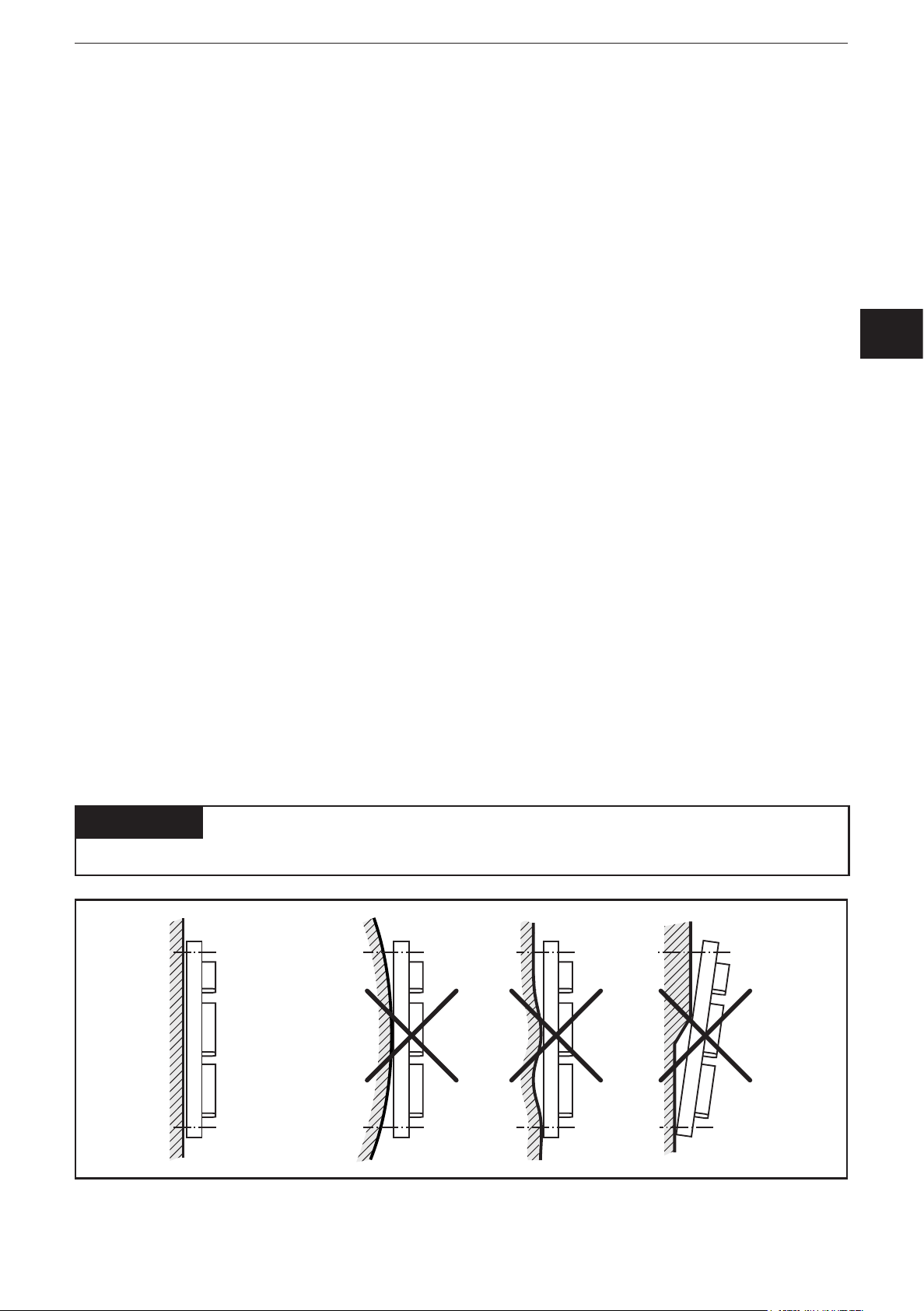
4.1 Mounting location
► The device is to be mounted in a dry and enclosed environment (e�g� control
panel of the driver‘s cab, separate control boxes, etc�)�
UK
ATTENTION
The housing must not be exposed to any torsion forces or mechanical stress�
5
Page 6

CabinetModule CR2012
4.2 Fixing
► Fix the device using 2 M4 x L screws via transversely arranged bore holes�
Tighten the screws alternately crosswise�
– Tightening torque: 1�5 Nm
– Mounting position: as required
– Hole dimensions: (→ 8.1 Dimensions, mechanics, electronics)
4.3 Cooling
► As the internal heating of the electronics is conducted away via the housing,
ensure sufficient heat dissipation�
6
Page 7
CabinetModule CR2012
5 Electrical connection
5.1 Connectors
The supply cables and inputs/outputs are connected via AMP crimp connectors on
the front of the device�
UK
Pin connection (→ 8.4 Wiring)
You can find more information about the available connector accessories at:
www�ifm�com → Data sheet direct → CR2012 → Accessories
5.2 Fuses
► To protect the whole system (wiring and device) the individual electric circuits
must be protected with max� 8 A�
7
Page 8
CabinetModule CR2012
6 Set-up
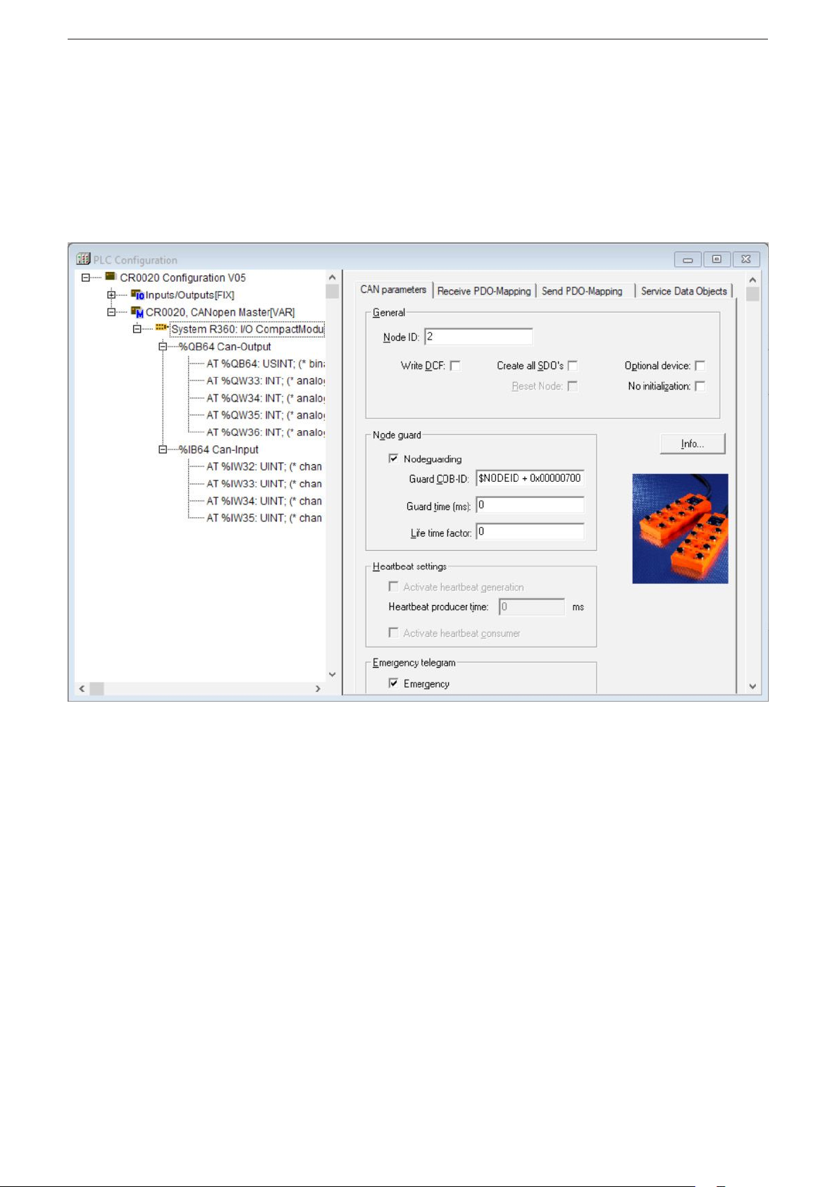
6.1 PLC configuration in CODESYS 2.3
Parameter setting of the device functions and of the CAN interface is directly done
from the application programmed with CODESYS 2�3� To do so, the „Electronic
Data Sheet“ (EDS) is integrated via the CODESYS PLC configuration�
CODESYS dialogue „PLC configuration“ (example)
For a description of the setting and application of the „PLC configuration“ dialogue
see the CODESY manual and the CODESYS online help�
8
Page 9
CabinetModule CR2012
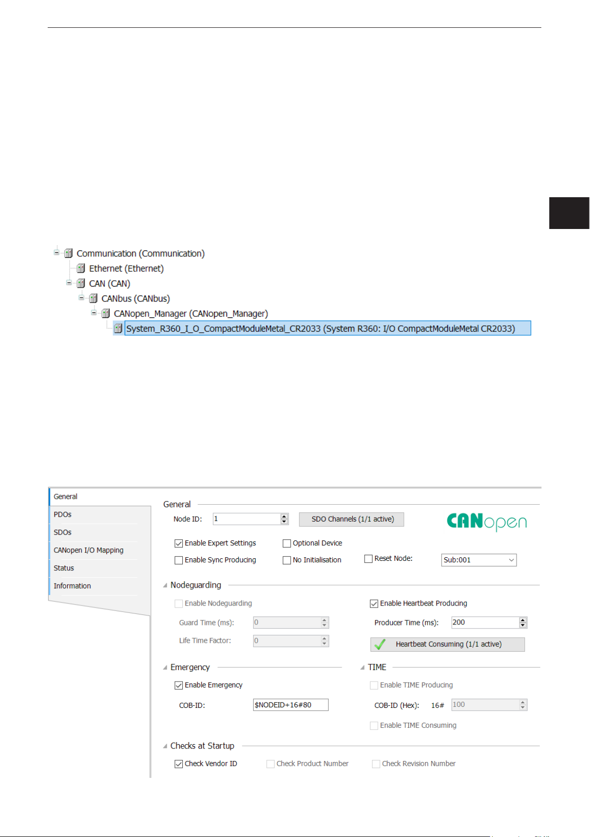
6.2 PLC configuration in CODESYS 3.5
The „Electronic Data Sheet“ (EDS) is installed in the [Device Repository]� Proceed
as follows in the main menu:
► Click on [Tools] / [Device Repository]�
► Select [Fieldbuses] / [CiA CANopen] / [CiA Remote Device] and click on [In-
stall]�
► Select EDS file and click on [Open]�
> In CODESYS 3�5 the devices are integrated as CiA remote devices in the de-
vice tree under a [CANopen_Manager] element�
The CANopen communication is configured via the CODESYS configuration
editor�
6.2.1 Heartbeat conguration
The function [Reset Node] must be activated on the tab [General] so that the
device applies the parameters set for heartbeat monitoring of the CANopen
Manager�
UK
9
Page 10

CabinetModule CR2012
6.2.2 SyncMonitoring
To activate the device-internal monitoring of the Sync cycle, the monitoring time
has to be written into the object directory entry 0x1006� This is possible by
supplementing the SDO list in the CANopen configurator or during the operating
time via the function block COP_SDOwrite�
The monitoring time is indicated in microseconds [μs].
6.3 Electronic Data Sheet
The EDS contains the description of all parameters and I/O data of the device in a
format defined by CANopen� The EDS files are provided for all CANopen slaves by
ifm electronic�
The EDS files are available at www�ifm�com�
10
Page 11

CabinetModule CR2012
7 Parameter setting
7.1 Automatic saving
Automatic saving of the communication and device parameters can be activated or
deactivated by means of the “save parameter” entry (object directory, index 1010,
S-Idx 01)�
● Value 0x00:
There is no automatic saving� Changed parameters are only valid until the device
is switched off or until the next reset�
UK
● Value 0x01:
Changed parameters will be saved if the string “save” is written in S-Idx 01� Otherwise changed parameters are only valid until the device is switched off or until the
next reset�
● Value 0x02:
Changed parameters are saved automatically�
7.2 Restoring the factory setting
With the function “restore” (object directory, index 1011, subindex 01) the factory
default values can be restored (except for the baud rate and the node ID)� They
become valid with the next power on�
11
Page 12

CabinetModule CR2012
7.3 Communication profiles; Idx 1000 to 1FFF
Parameters Index in
object
directory
COB ID Synch Object 1005 00 0x80 adjustable after PreOp
Communication Cycle 1006 00 0x00 (Off) adjustable immediately
Guard Time 100C 00 0x00 (Off) adjustable immediately
Life Time Factor 100D 00 0x00 adjustable immediately
Save Parameter 1010 01 0x02 (AutoSave ON) yes immediately
COB-ID EMCY 1014 00 0x80 + node ID adjustable after a reset
Consumer Heartbeat Time 1016 01 0x00 (Off) adjustable immediately
Producer Heartbeat Time 1017 00 0x00 (Off) adjustable immediately
COB-ID Rx PDO 1 1400 01 0x200 + node ID adjustable after PreOp
Trans Type Rx PDO 1 1400 02 0x01 (synchronous) adjustable immediately
COB-ID Rx PDO 2 1401 01 0x300 + node ID adjustable after PreOp
Trans Type Rx PDO 2 1401 02 0x01 (synchronous) adjustable immediately
COB-ID Tx PDO 1 1800 01 0x180 + node ID adjustable after PreOp
Default value (factory
preset)
Change saved
automatically
Change
effective
Trans Type Tx PDO 1 1800 02 0xFF (asynchronous) adjustable immediately
Inhibit Timer Tx PDO 1 1800 03 0x0000 adjustable immediately
Event Timer Tx PDO 1 1800 05 0x00 adjustable immediately
COB-ID Tx PDO 2 1801 01 0x280 + node ID adjustable after PreOp
Trans Type Tx PDO 2 1801 02 0x01 (synchronous) adjustable immediately
Inhibit Timer Tx PDO 2 1801 03 0x0000 adjustable immediately
Event Timer Tx PDO 2 1801 05 0x00 adjustable immediately
The life time factor 0 is interpreted as 1�The first guard protocol is interpreted as
"start guarding” even if guarding is not yet active at that time (guard time = 0)�
12
Page 13

7.4 Manufacturer-specific profiles; Idx 2000 to 6FFF
CabinetModule CR2012
Parameters Index in object
directory
Config� channel 1 2000 01 0x01 (Bin IN)
Config� channel 2 2000 02 0x01 (Bin IN)
Config� channel 3 2000 03 0x01 (Bin IN)
Config� channel 4 2000 04 0x01 (Bin IN)
Config� channel 5 2000 05 0x03 (Ana IN absolute)
Config� channel 6 2000 06 0x03 (Ana IN absolute)
Config� channel 7 2000 07 0x02 (Bin OUT + read
Config� channel 8 2000 08 0x02 (Bin OUT + read
Config� channel 9 2000 09 0x01 (Bin IN)
Config� channel 10 2000 0A 0x01 (Bin IN)
Config� channel 11 2000 0B 0x01 (Bin IN)
Config� channel 12 2000 0C 0x01 (Bin IN)
Default value
(factory preset)
back input)
back input)
Change saved
automatically
adjustable after PreOp
Change
effective
UK
Config� channel 13 2000 0D 0x03 (Ana IN absolute)
Config� channel 14 2000 0E 0x03 (Ana IN absolute)
Config� channel 15 2000 0F 0x02 (Bin OUT + read
back input)
Config� channel 16 2000 10 0x02 (Bin OUT + read
back input)
PWM frequency 2001 00 0x64 (100 Hz) adjustable after PreOp
Node ID * 20F0, 20F1 0x20 (0d32) yes after a reset
Baud rate * 20F2, 20F3 0x04 (125 Kbit/s) yes after a reset
Autostart 20F4 0x00 (Off) adjustable immediately
Entries in the object directory indexes 20F0/20F1 and/or 20F2/20F3 are only valid
if the rotary switches for baud rate and/or node ID are in the position “F”�
*) Observe rotary switch position!
Position and coding of the rotary switches (→ 8.2 Connecting, operating and display elements)
13
Page 14

CabinetModule CR2012
7.5 EMCY objects
The following error codes are supported according to DSP-301 and DSP-401:
EMCY code Error reg Additional
code
0x6100 0x11 0x00 "Internal Software":
0x6101 0x11 0x00 "Internal Software":
0x8100 0x11 0x00 "Monitoring" (guarding error)
0x8120 0x11 0x00 "Communication" (CAN error passive)
0x8200 0x11 0x00 "Monitoring" (synch error)
Description
overflow of an Rx queue; e�g� frequency of the Rx PDOs
too high
only external reset via an entry in 1003 00
overflow of a Tx queue; e�g� device does not
communicate with the bus
only external reset via an entry in 1003 00
no guard object is received for "guard time" x "life time
factor"
reset with the next communication
CAN controller has passed into the CAN error passive
state
for "communication cycle" no synch object is received;
only in OPERATIONAL
reset with the next synch OBJ or PREOP
7.6 Boot-up message
The module sends a boot-up message after application of the supply voltage or
after a reset, to inform a CANopen master in the network about its presence or a
restart�
To ensure the compatibility with older device versions, a boot-up message is sent
in accordance with CANopen specifications DS-301 V3 and V4�
14
Page 15

8 Technical data
Control systems
8.1 Dimensions, mechanics, electronics
CabinetModule CR2012
CR2012
CabinetModule
I/O module
digital and analogue
163
18 LED
±1
29
13
for R 360 system
16 inputs/outputs
42,3
63
CANopen interface
10...32 V DC
Application Connection of operating and display elements to CAN bus
to be installed in driver’s cabs, control panels or control boxes
Structure PCB without housing
Dimensions (l xwxh) 163 x 63 x 29±1mm
Installation via 2 transversely arranged bore holes
Protection IP00 (PCB without housing), to EN60529
4,5
(for mechanical protection potted in a potting tub)
142,3
UK
Possible I/O-configurations 8 digital inputs
(also see wiring) 4 digital/analogue inputs (to be configured via CANopen)
2 digital inputs/outputs, analogue outputs (to be configured via CANopen)
Inputs, digital for positive-switching sensor signals, switches or pushbuttons
Inputs, analogue • ratiometric, query of potentiometric signal transmitters (e.g. joystick)
(to be configured via CANopen) • absolute, conversion of input voltage (0...10 V) in 8-bit value
Outputs for triggering pilot lights etc.
Connections AMP crimp connector, to be clipped into place and thus vibration-resistant,
Inputs/outputs 2 plugs, 18 poles
Operating voltage and CAN bus 1 plug, 6 poles
Operating voltage U
Current consumption ≤ 100 mA, without load (external fuse with max. 5 A)
Operating/storage temperature -40...+85°C / -40...+85°C
Controller 16 bits Fujitsu MB90F543
Interface CAN interface 2.0 B, ISO 11898
Baud rate 20 Kbits/s...1 Mbit/s (default setting 125 Kbits/s)
Controller 16 bits Fujitsu MB90F543
Communication profile CANopen, CiA DS 301 version 4, CiA DS 401 version 2.1
Programming system from CoDeSys 2.3 via EDS
Node ID (default) hex 20 (= dec 32)
Status LED CANopen: 2 LEDs (green, red)
Accessories Order no. EC2053
(to be ordered separately) Plug set for CabinetModules, wirable, consisting of:
B
adjustable via rotary switch (1...14) or CANopen object directory (1...127)
2 digital inputs/outputs (to be configured via CANopen)
protected against reverse polarity
10...32 V DC
adjustable via rotary switches or CANopen object directory
Inputs/outputs: 16 LEDs (yellow)
AMP crimp housing, 1 x 6 poles, 2x18 poles
incl. crimp contacts (Junior Power Timer)
15
Page 16

CabinetModule CR2012
Control systems
8.2 Connecting, operating and display elements
CR2012 Technical data
Operating and indicating elements
Connector
Rotary switch
hex-coded
S1
Baud rate
S2
Node ID
AMP
Crimp connector
Hex-code switch coding
Operating states (LEDs)
Switch Position Description
S1 0 1000 Kbits/s
Baud rate 1 800 kBits/s
2 500 Kbit/s
3 250 Kbit/s
4 125 Kbit/s
5 100 Kbit/s
6 50 Kbit/s
7 20 Kbit/s
8...E not defined
F adjustment via object directory (default)
S2 0 not defined
Node-ID 1...E 1...14
F adjustment via object directory (default)
LED State Description
PWR (green) OFF no supply voltage
ON module in stand-by mode
CANopen status: PREOPERATIONAL / PREPARED
outputs = OFF
1 x ON module in stop mode
CANopen status: STOP
outputs = OFF
2.5 Hz module active
CANopen status: OPERATIONAL
outputs are updated
DIA (red) OFF communication OK
ON communication disturbed, CAN bus OFF
1 x ON communication disturbed:
• CAN error warning level exceeded
2 x ON • node guard / heartbeat error
(if node guarding / heartbeat is activated)
3 x ON • no synch objects
(if synch monitoring is activated)
IN (yellow) OFF input not switched
ON input switched
OUT (yellow) OFF binary output not switched (OFF)
analogue output:
PWM preset value < 1% measuring range
ON binary output switched (ON)
analogue output:
PWM preset value > 2% measuring range
0
•
•
2
E
•
•
4
C
•
•
6
A
•
•
8
ifm electronic gmbh • Friedrichstraße 1 • 45128 Essen
16
25.04.2013We reserve the right to make technical alterations without prior notice! CR2012 / page 2
Page 17

CabinetModule CR2012
Control systems
8.3 Characteristics of the inputs/outputs, test standards and regulations
CR2012 Characteristics of the inputs / outputs
Inputs
Channels 1...4, channels 9...12 • 8 inputs for positive sensor signals
Channels 7...8, channels 15...16 • 4 inputs for positive sensor signals
Channels 5...6, channels 13...14 • 4 inputs, to be configured via CANopen:
Outputs
Channels 7, 15 • 2 positive-switching outputs; short-circuit and overload protected;
Channels 8, 16 • 2 PWM outputs (high side), variable frequency
For each input the pins +UBand Bin INx are available
Can be used as an alternative to the 4 outputs.
For input and output one pin is available (double configuration).
The inputs can be used to read back the output signals.
Current consumption I
= 4 mA (for UB= 10 V)
IN
I
= 17 mA (for UB= 30 V)
IN
Switching threshholds HIGH = 8 V LOW = 2.5 V
Switching frequency 25 Hz max. (for ti = tp)
for ratiometric measurement for potentiometric transducers (e.g. joystick)
For each input the pins +U
, Ana INx and GND are available
B
Input resistance typ. 50 kΩ
Resolution based on 1/2 supply voltage U
B
= ± 200 steps (for UB= 12 V), ± 400 steps (for UB= 24 V)
for absolute value measurement 0...10 V
For each input the pins Ana INx and GND are available
Input resistance typ. 50 kΩ
Resolution 8 bits
Accuracy typ. ± 2 LSB
as binary inputs
For each input the pins +U
and Bin INx are available
B
Input resistance typ. 50 kΩ
Switching threshhold at 1/2 supply voltage U
the supply voltage U
is switched without additional fuse.
B
B
The output states can be read back (see inputs).
For each input the pins Bin OUTx and GND are available.
When inductive loads are switched, free-wheeling diodes must be connected in
parallel with the load!
Switching current max. 500 mA
PWM frequency 20...250 Hz
Pulse duty factor 0...1000 ‰
Resolution 1 ‰
Switching current max. 500 mA
UK
Test standards and regulations
Immunity to to ISO 7637-2, pulses 2a, 3a, 3b, 4, severity level 4, function state A
conducted interference to ISO 7637-2, pulse 5, severity level 3, function state A
to ISO 7637-2, pulse 1, 2b, severity level 4, function state C
Immunity to interfering fields to UN/ECE-R10 at 100V/m (E1 type approval)
and EN 61000-6-2: 2005 (CE)
Interference emission to UN/ECE-R10 (E1 type approval)
and EN 61000-6-3: 2007 (CE)
Tests for railway applications EN 50155 clause 12.2 mechanical/climatic tests
EN 50121-3-2 EMC noise emission and noise immunity
additional information on request
ifm electronic gmbh • Friedrichstraße 1 • 45128 Essen
25.04.2013We reserve the right to make technical alterations without prior notice! CR2012 / page 3
17
Page 18

CabinetModule CR2012
Control systems
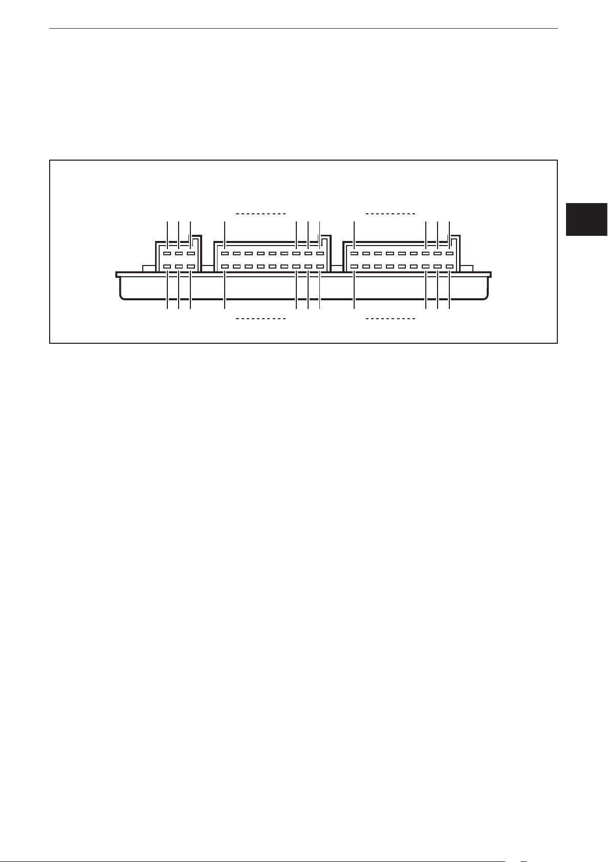
8.4 Wiring
CR2012 Wiring
View of the unit
Wiring
Plug X1
Pin Potential Inputs Outputs
1 channel 1 Bin IN 1 – – –
2 +U
B
3 channel 2 Bin IN 2 – – –
4 +U
B
5 channel 3 Bin IN 3 – – –
6 +U
B
7 channel 4 Bin IN 4 – – –
8 +U
9 +U
10 +U
B
B
B
11 channel 5 Bin IN 5 Ana IN 5 – –
12 channel 6 Bin IN 6 Ana IN 6 – –
13 GND
14 GND
15 channel 7 Bin IN 7 – Bin OUT 7
16 GND
17 channel 8 Bin IN 8 – Bin OUT 8 PWM 8
18 GND
Plug X2
1 channel 9 Bin IN 9 – – –
2 +U
B
3 channel 10 Bin IN 10 – – –
4 +U
B
5 channel 11 Bin IN 11 – – –
6 +U
B
7 channel 12 Bin IN 12 – – –
8 +U
9 +U
10 +U
B
B
B
11 channel 13 Bin IN 13 Ana IN 13 – –
12 channel 14 Bin IN 14 Ana IN 14 – –
13 GND
14 GND
15 channel 15 Bin IN 15 – Bin OUT 15
16 GND
17 channel 16 Bin IN 16 – Bin OUT 16 PWM 16
18 GND
Plug X3
1 +U
B
2 GND
3 +U
B
4 GND
5 CAN_L
6 CAN_H
ifm electronic gmbh • Friedrichstraße 1 • 45128 Essen
18
25.04.2013We reserve the right to make technical alterations without prior notice! CR2012 / page 4
Page 19

CabinetModule CR2012
9 Maintenance, repair and disposal
► Do not open the housing, as the device does not contain any components
which must be maintained by the user� The device must only be repaired by the
manufacturer�
► Dispose of the device in accordance with the national environmental regula-
tions�
10 Approvals/standards
Test standards and regulations (→ 8 Technical data)
The CE Declaration of Conformity and the E1 approval are available at:
www�ifm�com → Data sheet direct → CR2012 → Approvals
UK
19
Page 20

CabinetModule CR2012
11 Anhang / Appendix Objektverzeichnis / Object directory
11.1 Communication profiles; Idx 1000 to 1FFF
Index S-Idx Name Type Default Description
1000 0 device type ro u32 0x000F0191 I/O-module profile DS401
digital/analogue inputs/outputs
1001 0 error register ro u8 0x00
1003 0 pre-definded error field rw u8 0x00 up to 4 entries in error history
supported
error history can be deleted by
writing '0' to this entry
1 error history ro u32 0x00000000
2 error history ro u32 0x00000000
3 error history ro u32 0x00000000
4 error history ro u32 0x00000000
1005 0 COB ID SYNC rw u32 0x00000080
1006 0 communication cycle
period
1008 0 device name ro str CR2012
1009 0 HW Version ro str HW Vx�x
100A 0 SW Version ro str SW Vx�x
100C 0 guard time rw u16 0x0000 time in ms
100D 0 life time factor rw u8 0x00 if no "node guarding" is received
rw u32 0x00000000 max� time between 2 synch
objects in µs; useful resolution
= 1 ms
within this time the module
expects a "node guarding" of the
network master
0 = node guarding deactivated
for "guard time" x "life time", the
module generates an EMCY
the result form "guard time" x "life
time" must be between 0 and
65535
1010 0 number of save
options
1 save parameter rw u32 0x00000002 0x00000000 = no save
1011 0 number of restore
options
1 restore default
parameter
20
ro u8 0x01
0x00000001 = saving all
parameters after the string 'save'
is written to this entry
0x00000002 = auto save
ro u8 0x01
rw u32 0x00000001 restore all parameters to default
value after next reset if the string
'load' is written to this entry
Page 21

CabinetModule CR2012
Index S-Idx Name Type Default Description
1014 0 COB ID EMCY rw u32 0x40000080
+ NodeID
1016 0 number of monitored
devices
1 consumer heartbeat
time
1017 0 producer heartbeat
time
1018 0 number of identity
objects
1 vendor ID ro u32 0x0069666D
1400 0 highest numbered
subindex Receive
PDO 1
ro u8 0x01
rw u32 0x00000000 heartbeat monitoring time for
rw u16 0x0000 time interval [ms] where the
ro u8 0x04
ro u8 0x02
module generates EMCY
messages
(bit 30 = 1)
node n
monitoring of only one node is
supported
0x0nntttt = monitoring time [ms]
0x0nntttt = node number
(if nn or tttt = 0, no monitoring is
carried out)
module generates a producer
heartbeat
UK
1 COB ID Receive
PDO 1
2 transmission type Rec
PDO 1
1401 0 highest numbered
subindex Receive
PDO 2
1 COB ID Receive
PDO 2
2 transmission type Rec
PDO 2
1600 0 number of application
objects linked with Rec
PDO 1
1 1st mapping object
Rec PDO 1
2 2nd mapping object
Rec PDO 1
rw u32 0x00000200
+ NodeID
rw u8 0x01 0x01���0xF0 = synch cyclic
ro u8 0x02
rw u32 0x00000300
+ NodeID
rw u8 0x01 0x01���0xF0 = synch cyclic
rw u8 0x01
rw u32 0x08010062 index 6200, subindex 1, 8 bits
rw u32 0x00000000 no object
PDO is valid (bit 31 = 0)
0xFE���0xFF = asynch
(immediately)
PDO is valid (bit 31 = 0)
0xFE���0xFF = asynch
(immediately)
3 3rd mapping object
Rec PDO 1
4 4th mapping object
Rec PDO 1
rw u32 0x00000000 no object
rw u32 0x00000000 no object
21
Page 22

CabinetModule CR2012
Index S-Idx Name Type Default Description
5 5th mapping object
Rec PDO 1
6 6th mapping object
Rec PDO 1
7 7th mapping object
Rec PDO 1
8 8th mapping object
Rec PDO 1
1601 0 number of application
objects linked with Rec
PDO 2
1 1st mapping object
Rec PDO 2
2 2nd mapping object
Rec PDO 2
3 3rd mapping object
Rec PDO 2
4 4th mapping object
Rec PDO 2
rw u32 0x00000000 no object
rw u32 0x00000000 no object
rw u32 0x00000000 no object
rw u32 0x00000000 no object
rw u8 0x02
rw u32 0x10011464 index 6414 subindex 1, 16 bits
rw u32 0x10021464 index 6414 subindex 2, 16 bits
rw u32 0x00000000 no object
rw u32 0x00000000 no object
5 5th mapping object
Rec PDO 2
6 6th mapping object
Rec PDO 2
7 7th mapping object
Rec PDO 2
8 8th mapping object
Rec PDO 2
1800 0 highest numbered
subindex Transmit
PDO 1
1 COB ID Transmit
PDO 1
2 transmission type
Trans PDO 1
3 inhibit timer Trans
PDO 1
5 event timer Trans
PDO 1
rw u32 0x00000000 no object
rw u32 0x00000000 no object
rw u32 0x00000000 no object
rw u32 0x00000000 no object
ro u8 0x05
rw u32 0x00000180
+ NodeID
rw u8 0xFF 0x01���0xF0 = synch cyclic
rw u16 0x0000 min� interval for transmission (in
rw u16 0x0000 max transfer break in trans type
PDO is valid (bit 31 = 0)
0xFE���0xFF = asynch
(immediately)
100 µs)
"asynch" (0���65535 ms)
when this time has elapsed the
PDO is transferred even if the
appl� event has not occurred
1801 0 highest numbered
subindex Transmit
PDO 2
22
ro u8 0x05
Page 23

CabinetModule CR2012
Index S-Idx Name Type Default Description
1 COB ID Transmit
PDO 2
2 transmission type
Trans PDO 2
3 inhibit timer Trans
PDO 2
5 event timer Trans
PDO 2
1A00 0 number of application
objects linked with
Trans PDO 1
1 1st mapping object
Trans PDO 1
2 2nd mapping object
Trans PDO 1
3 3rd mapping object
Trans PDO 1
rw u32 0x00000280
+ NodeID
rw u8 0x01 0x01���0xF0 = synch cyclic
rw u16 0x0000 min� interval for transmission (in
rw u16 0x0000 max transfer break in trans type
rw u8 0x01
rw u32 0x10010061 index 6100, subindex 1, 16 bits
rw u32 0x00000000 no object
rw u32 0x00000000 no object
PDO is valid (bit 31 = 0)
0xFE���0xFF = asynch
(immediately)
100 µs)
"asynch" (0���65535 ms)
when this time has elapsed the
PDO is transferred even if the
appl� event has not occurred
UK
4 4th mapping object
Trans PDO 1
5 5th mapping object
Trans PDO 1
6 6th mapping object
Trans PDO 1
7 7th mapping object
Trans PDO 1
8 8th mapping object
Trans PDO 1
1A01 0 number of application
objects linked with
Trans PDO 2
1 1st mapping object
Trans PDO 2
2 2nd mapping object
Trans PDO 2
3 3rd mapping object
Trans PDO 2
rw u32 0x00000000 no object
rw u32 0x00000000 no object
rw u32 0x00000000 no object
rw u32 0x00000000 no object
rw u32 0x00000000 no object
rw u8 0x04
rw u32 0x10010164 index 6401, subindex 1, 16 bits
rw u32 0x10020164 index 6401, subindex 2, 16 bits
rw u32 0x10030164 index 6401, subindex 3, 16 bits
4 4th mapping object
Trans PDO 2
5 5th mapping object
Trans PDO 2
rw u32 0x10040164 index 6401, subindex 4, 16 bits
rw u32 0x00000000 no object
23
Page 24

CabinetModule CR2012
Index S-Idx Name Type Default Description
6 6th mapping object
Trans PDO 2
7 7th mapping object
Trans PDO 2
8 8th mapping object
Trans PDO 2
rw u32 0x00000000 no object
rw u32 0x00000000 no object
rw u32 0x00000000 no object
24
Page 25

CabinetModule CR2012
11.2 Manufacturer-specific profiles; Idx 2000 to 6FFF
Index S-Idx Name Type Default Description
2000 0 number of IOs ro u8 0x10
1 configuration channel 1rw u8 0x01 0x00 = off
0x01 = binary input
2 configuration channel 2rw u8 0x01 0x00 = off
0x01 = binary input
3 configuration channel 3rw u8 0x01 0x00 = off
0x01 = binary input
4 configuration channel 4rw u8 0x01 0x00 = off
0x01 = binary input
5 configuration channel 5rw u8 0x03 0x00 = off
0x01 = binary input
0x03 = analog input absolute
(voltage 0���10 V; 0x00���0xFF)
0x06 = analog input ratiometric
UK
6 configuration channel 6rw u8 0x03 0x00 = off
0x01 = binary input
0x03 = analog input absolute
(voltage 0���10 V; 0x00���0xFF)
0x06 = analog input ratiometric
7 configuration channel 7rw u8 0x02 0x00 = off
0x01 = binary input
0x02 = binary output + read back
input
8 configuration channel 8rw u8 0x02 0x00 = off
0x01 = binary input
0x02 = binary output + read back
input
0x04 = analogue output (PWM
20���250 Hz)
9 configuration channel 9rw u8 0x01 0x00 = off
0x01 = binary input
A configuration channel 10rw u8 0x01 0x00 = off
0x01 = binary input
B configuration channel 11rw u8 0x01 0x00 = off
0x01 = binary input
C configuration channel 12rw u8 0x01 0x00 = off
0x01 = binary input
D configuration channel 13rw u8 0x03 0x00 = off
0x01 = binary input
0x03 = analog input absolute
(voltage 0���10 V; 0x00���0xFF)
0x06 = analog input ratiometric
25
Page 26

CabinetModule CR2012
Index S-Idx Name Type Default Description
E configuration channel 14rw u8 0x03 0x00 = off
0x01 = binary input
0x03 = analog input absolute
(voltage 0���10 V; 0x00���0xFF)
0x06 = analog input ratiometric
F configuration channel 15rw u8 0x02 0x00 = off
0x01 = binary input
0x02 = binary output + read back
input
10 configuration channel 16rw u8 0x02 0x00 = off
0x01 = binary input
0x02 = binary output + read back
input
0x04 = analogue output (PWM
20���250 Hz)
2001 0 PWM frequency rw u8 0x64 20��250 Hz
PWM frequency for channel 8
and 16
20F0 0 CANopen node ID rw u8 0x20 1���127
20F1 0 CANopen node ID rw u8 0x20 The entries 20F0/20F1 must
always contain identical values�
The new entries are valid after
a reset (switching the module
off/on)�
Values outside the permissible
ranges will be rejected�
20F2 0 CAN baud rate rw u8 0x03 0 = 1000 Kbaud
1 = 500 Kbaud
2 = 250 Kbaud
3 = 125 Kbaud
4 = 100 Kbaud
5 = 50 Kbaud
6 = 20 Kbaud
20F3 0 CAN baud rate rw u8 0x03 The entries 20F2/20F3 must
always contain identical values�
The new entries are valid after
a reset (switching the module
off/on)�
Values outside the permissible
ranges will be rejected�
20F4 0 auto start rw u16 0x00 Time after reaching
Preoperational State to change
to Operational State�
0���5000 ms
0 = auto start deactivated
2500 0 number of 8bit user
variables
ro u8 0x0A Idx 2500���2530 = range which
can be freely used for customerspecific entries
1 8bit user variable 1 rw u8
2 8bit user variable 2 rw u8
26
Page 27

CabinetModule CR2012
Index S-Idx Name Type Default Description
3 8bit user variable 3 rw u8
4 8bit user variable 4 rw u8
5 8bit user variable 5 rw u8
6 8bit user variable 6 rw u8
7 8bit user variable 7 rw u8
8 8bit user variable 8 rw u8
9 8bit user variable 9 rw u8
A 8bit user variable 10 rw u8
2510 0 number of 16bit user
variables
1 16bit user variable 1 rw u16
2 16bit user variable 2 rw u16
3 16bit user variable 3 rw u16
4 16bit user variable 4 rw u16
5 16bit user variable 5 rw u16
6 16bit user variable 6 rw u16
7 16bit user variable 7 rw u16
8 16bit user variable 8 rw u16
9 16bit user variable 9 rw u16
A 16bit user variable 10 rw u16
2520 0 number of 32bit user
variables
UK
ro u8 0x0A Idx 2500���2530 = range which
can be freely used for customerspecific entries
ro u8 0x0A Idx 2500���2530 = range which
can be freely used for customerspecific entries
1 32bit user variable 1 rw u32
2 32bit user variable 2 rw u32
3 32bit user variable 3 rw u32
4 32bit user variable 4 rw u32
5 32bit user variable 5 rw u32
6 32bit user variable 6 rw u32
7 32bit user variable 7 rw u32
8 32bit user variable 8 rw u32
9 32bit user variable 9 rw u32
A 32bit user variable 10 rw u32
2530 0 number of user strings ro u8 0x02 Idx 2500���2530 = range which
can be freely used for customerspecific entries
1 user string 1 rw str 16 characters
27
Page 28

CabinetModule CR2012
Index S-Idx Name Type Default Description
2 user string 2 rw str 16 characters
6100 0 number of binary
inputs (16bit)
1 binary inputs ro u8 - bits 0���15: binary inputs channel
6200 0 number of binary
outputs (8bit)
1 binary outputs wo u8 0x00 0b0000 0001 = channel 7
6401 0 number of analogue
inputs
1 analogue input
channel 5
2 analogue input
channel 6
ro u8 0x01
1����16
ro u8 0x01
0b0000 0010 = channel 8
0b0000 0100 = channel 15
0b0000 1000 = channel 16
ro u8 0x04
ro s16 - for configuration absolute
measurement
-> 0x00���0xFF
for configuration ratiometric
measurement
-> -1000���0���+1000
ro s16 - (see above)
3 analogue input
channel 13
4 analogue input
channel 14
6414 0 number of analogue
outputs (ifm specific)
1 analogue output
channel 8
2 analogue output
channel 16
ro s16 - (see above)
ro s16 - (see above)
ro u8 0x02
wo u16 0x0000 0���1000 per mille
wo u16 0x0000 0���1000 per mille
28
 Loading...