

Page 1
Montage- und
Installationshinweise
Mounting and
installation instructions
Prozess- und Dialoggerät
PDM 360 compact
Process and dialogue module
PDM 360 compact
CR1055
CR1056
DEUTSCH
ENGLISH
7390593 /00 03 / 2015
R
Page 2

PROZESS- UND DIALOGGERÄT PDM360 COMPACT
SEITE 2
Sicherheitshinweise
Diese Beschreibung ist Bestandteil des Gerätes. Sie enthält Texte
und Abbildungen zum korrekten Umgang mit dem Gerät und muss
vor einer Installation oder dem Einsatz gelesen werden.
Befolgen Sie die Angaben der Beschreibung. Nichtbeachten der Hinweise, Betrieb
außerhalb der nachstehend bestimmungsgemäßen Verwendung, falsche Installation oder fehlerhafte Handhabung können schwerwiegende Beeinträchtigungen
der Sicherheit von Menschen und Anlagen zur Folge haben.
Die Anleitung richtet sich an Personen, die im Sinne der EMV- und der Niederspannungs-Richtlinie als „fachkundig“ angesehen werden können. Das Prozessund Dialoggerät ist von einer Elektrofachkraft (Programmierer bzw. Servicetechniker) einzubauen und in Betrieb zu setzen.
Wird das Gerät nicht vom mobilen Bordnetz (12/24 V Batteriebetrieb) versorgt, ist
darauf zu achten, dass die externe Spannung gemäß den Kriterien für sichere
Kleinspannung (SELV) erzeugt und zugeführt wird.
Die Verdrahtung aller in Zusammenhang mit dem SELV-Kreis des Geräts stehenden Signale muss ebenfalls den SELV-Kriterien entsprechen (sichere Schutzkleinspannung, galvanisch sicher getrennt von anderen Stromkreisen).
Wird die zugeführte SELV-Spannung extern geerdet (SELV wird zu PELV), so geschieht dies in der Verantwortung des Betreibers und im Rahmen der dort geltenden nationalen Installationsvorschriften. Alle Aussagen in dieser Bedienungsanleitung beziehen sich auf das bezügl. der SELV-Spannung nicht geerdete Gerät.
An den Anschlusssteckern dürfen nur die in den technischen Daten, bzw. auf
dem Geräteaufdruck angegebenen Signale eingespeist bzw. die zugelassenen Zubehörkomponenten der ifm electronic gmbh angeschlossen werden.
Schalten Sie alle Geräte extern spannungsfrei bevor Sie irgendwelche Arbeiten an
ihnen vornehmen. Schalten Sie ggf. auch unabhängig versorgte Ausgangslastkreise ab.
Bei Fehlfunktionen oder Unklarheiten setzen Sie sich bitte mit dem Hersteller in
Verbindung. Eingriffe in das Gerät können schwerwiegende Beeinträchtigungen
der Sicherheit von Menschen und Anlagen zur Folge haben. Sie sind nicht zulässig und führen zu Haftungs- und Gewährleistungsausschluss.
Elektromagnetische Verträglichkeit
Dies ist eine Einrichtung der Klasse A. Diese Einrichtung kann im Wohnbereich
Funkstörungen verursachen. In diesem Fall kann vom Betreiber verlangt werden,
angemessene Maßnahmen durchzuführen
Page 3

Inhalt
1. Bestimmungsgemäße Verwendung . . . . . . . . . . . . . . . . . . . . Seite 4
Eigenschaften im Überblick . . . . . . . . . . . . . . . . . . . . . . . . . . Seite 4
2. Programmierung. . . . . . . . . . . . . . . . . . . . . . . . . . . . . . . . . . Seite 5
Konfiguration und Onlinehilfe . . . . . . . . . . . . . . . . . . . . . . . . Seite 5
3. Montage
Montagezubehör . . . . . . . . . . . . . . . . . . . . . . . . . . . . . . . . . Seite 6
Dichtung/Vibrationsdämpfung . . . . . . . . . . . . . . . . . . . . . . . . Seite 6
Schalttafeleinbau mit Haltewinkel (Fixing-Set) . . . . . . . . . . . . . Seite 7
Konsoleneinbau mit Befestigungsclips (Snap-in Set) . . . . . . . . Seite 8
Aufbaumontage mit RAM®-Mount-System. . . . . . . . . . . . . . . Seite 9
4. Elektrischer Anschluss . . . . . . . . . . . . . . . . . . . . . . . . . . . . . . Seite 10
5. Wartung, Instandsetzung und Entsorgung . . . . . . . . . . . . . . . Seite 11
Anhang
Technische Daten CR1055
Maße. . . . . . . . . . . . . . . . . . . . . . . . . . . . . . . . . . . . . . . . . . Seite 12
Anzeige . . . . . . . . . . . . . . . . . . . . . . . . . . . . . . . . . . . . . . . . Seite 12
Mechanische Daten . . . . . . . . . . . . . . . . . . . . . . . . . . . . . . . Seite 12
Elektrische Daten . . . . . . . . . . . . . . . . . . . . . . . . . . . . . . . . . Seite 12
Schnittstellen . . . . . . . . . . . . . . . . . . . . . . . . . . . . . . . . . . . . Seite 13
Software/Programmierung. . . . . . . . . . . . . . . . . . . . . . . . . . . Seite 13
Sonstige Ausstattung . . . . . . . . . . . . . . . . . . . . . . . . . . . . . . Seite 13
Zulassungen/Prüfungen . . . . . . . . . . . . . . . . . . . . . . . . . . . . . Seite 13
Anschlussbelegung . . . . . . . . . . . . . . . . . . . . . . . . . . . . . . . . Seite 13
Technische Daten CR1056
Maße. . . . . . . . . . . . . . . . . . . . . . . . . . . . . . . . . . . . . . . . . . Seite 14
Anzeige . . . . . . . . . . . . . . . . . . . . . . . . . . . . . . . . . . . . . . . . Seite 14
Mechanische Daten . . . . . . . . . . . . . . . . . . . . . . . . . . . . . . . Seite 14
Elektrische Daten . . . . . . . . . . . . . . . . . . . . . . . . . . . . . . . . . Seite 14
Schnittstellen . . . . . . . . . . . . . . . . . . . . . . . . . . . . . . . . . . . . Seite 15
Software/Programmierung. . . . . . . . . . . . . . . . . . . . . . . . . . . Seite 15
Sonstige Ausstattung . . . . . . . . . . . . . . . . . . . . . . . . . . . . . . Seite 15
Zulassungen/Prüfungen . . . . . . . . . . . . . . . . . . . . . . . . . . . . . Seite 15
Anschlussbelegung . . . . . . . . . . . . . . . . . . . . . . . . . . . . . . . . Seite 15
Kenndaten der Ein-/Ausgänge . . . . . . . . . . . . . . . . . . . . . . . . Seite 16
DEUTSCH
PROZESS- UND DIALOGGERÄT PDM 360 COMPACT
SEITE 3
Page 4

1. Bestimmungsgemäße Verwendung
Das Prozess- und Dialoggerät PDM360 compact ist ein programmierbares Grafikdisplay zur Steuerung, Parametrierung und Bedienung von mobilen Maschinen
und Anlagen.
Die Kommunikation mit anderen Systemkomponenten, wie z.B. dezentrale I/OModule, erfolgt über eine CAN-Schnittstelle mit dem CANopen Protokoll.
Die Ethernet- und RS-232 Schnittstelle sowie die Ein-/Ausgänge (nur CR1056) bilden eine universelle Plattform für die Vernetzung und Kommunikation mit anderen Geräten.
Das Prozess- und Dialoggerät PDM360 compact ist nicht für sicherheitsrelevante Aufgaben im Sinne des Personenschutzes zugelassen.
Eigenschaften im Überblick
• 3,8" (320 x 240 Pixel) Display
• 3 hinterleuchtete, frei programmiergbare Funktionstasten
• 1 Drehgeber mit Drucktaster
• Geschlossenes Metallgehäuse (IP 67) für die Ein- und Aufbaumontage im
Außen- oder Kabinenbereich
• Frei programmierbar nach IEC 61131-3 mit Target-Visualisierung
• 32-Bit-Controller und Embedded Linux Betriebssystem
• CAN-Schnittstelle mit CANopen Protokoll
• Ethernet- und RS-232 Schnittstelle
PROZESS- UND DIALOGGERÄT PDM 360 COMPACT
SEITE 4
¹)Downloadbereich mit Anmeldung
Page 5

2. Programmierung
Die Applikationssoftware kann vom Anwender mit dem IEC 61131-3 konformen
Programmiersystem CoDeSys (ab Version 2.3.5) erstellt werden.
Als Download-File (HTML-Datei) steht die ifm Onlinehilfe CoDeSys V2.3 im Internet zur Verfügung:
➔ Datenblatt-Suche ➔ CR105... ➔ Download/Software
1)
Für die sichere Funktion der vom Anwender erstellten Applikationsprogram-
me ist dieser selbst verantwortlich. Bei Bedarf muss er zusätzlich entsprechend der nationalen Vorschriften eine Abnahme durch entsprechende Prüf- und
Überwachungsorganisationen durchführen lassen.
Konfiguration und Onlinehilfe
Im Auslieferungszustand ist das PDM 360 compact für die Programmierung mit
CoDeSys ab Version 2.3.5 vorbereitet.
Gleichzeitiges Drücken der Tasten F1 und F2 beim Einschalten der Versorgungsspannung öffnet das Konfigurations-Menü „PDM Setup“:
Informationen zur Programmierung und Bedienung entnehmen Sie bitte der
PDM-Onlinehilfe auf der CD-ROM „ecolog – Software, tools and documentation“
(Art.-Nr. CP9006).
Die PDM-Onlinehilfe enthält Beschreibungen zu den Themen:
• PDM 360 Geräte Setup
• Programmier- und Kommunikationsschnittstellen
• Projektneuerstellung
• Bibliotheken
• PDM 360 Geräte Update.
www.ifm-electronic.com
DEUTSCH
PROZESS- UND DIALOGGERÄT PDM 360 COMPACT
SEITE 5
Das PDM Setup ermöglicht die Einstellungen für die Kommunikation
und Dateiverwaltung.
Die Anwahl der Menüpunkte erfolgt
durch Drehen des Drehgebers; ein
Druck auf die Drehgebertaste führt
zum jeweiligen Untermenü.
Nach Verlassen des Setups kann ein
Projekt geladen werden. Um die Bedienelemente, Schnittstellen und sonstigen internen Funktionen des Gerätes zu nutzen, stehen Bibliotheken
(.lib) zur Verfügung. Sie müssen in
das Applikationsprogramm eingebunden werden.
Screenshot CR1056
Page 6
PROZESS- UND DIALOGGERÄT PDM 360 COMPACT
SEITE 6
3. Montage
■ Montagezubehör
Das Gerät wird ohne Montagezubehör geliefert.
Abhängig vom vorgesehen Einbauort und von der Einbauweise steht folgendes
Montagezubehör zur Verfügung:
• EC1450, Dichtung/Vibrationsdämpfung für den Konsolen-/Schalttafeleinbau
• EC1452, Snap-in Set für den Konsoleneinbau*
• EC1453, Fixing Set für den Schalttafeleinbau*
• EC1410...EC1414, RAM®-Mount-System für die Aufbaumontage
Informationen zum verfügbaren Zubehör unter:
➔ Datenblatt-Suche ➔ z.B. CR1056 ➔ Zubehör
*) Das Snap-in Set (EC1452) und das Fixing Set (EC1453) nur zusammen mit der
Dichtung/Vibrationsdämpfung (EC1450) einsetzen.
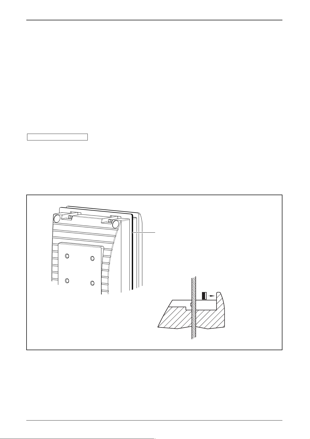
■ Dichtung/Vibrationsdämpfung
Dichtung/Vibrationsdämpfung von hinten über das Gerät stülpen.
www.ifm-electronic.com
EC1450
Dichtung/Vibrationsdämpfung für
PDM360 smart, PDM360 compact
Die Polyesterfolie liegt
auf dem Dialoggerät
Page 7
DEUTSCH
PROZESS- UND DIALOGGERÄT PDM 360 COMPACT
SEITE 7
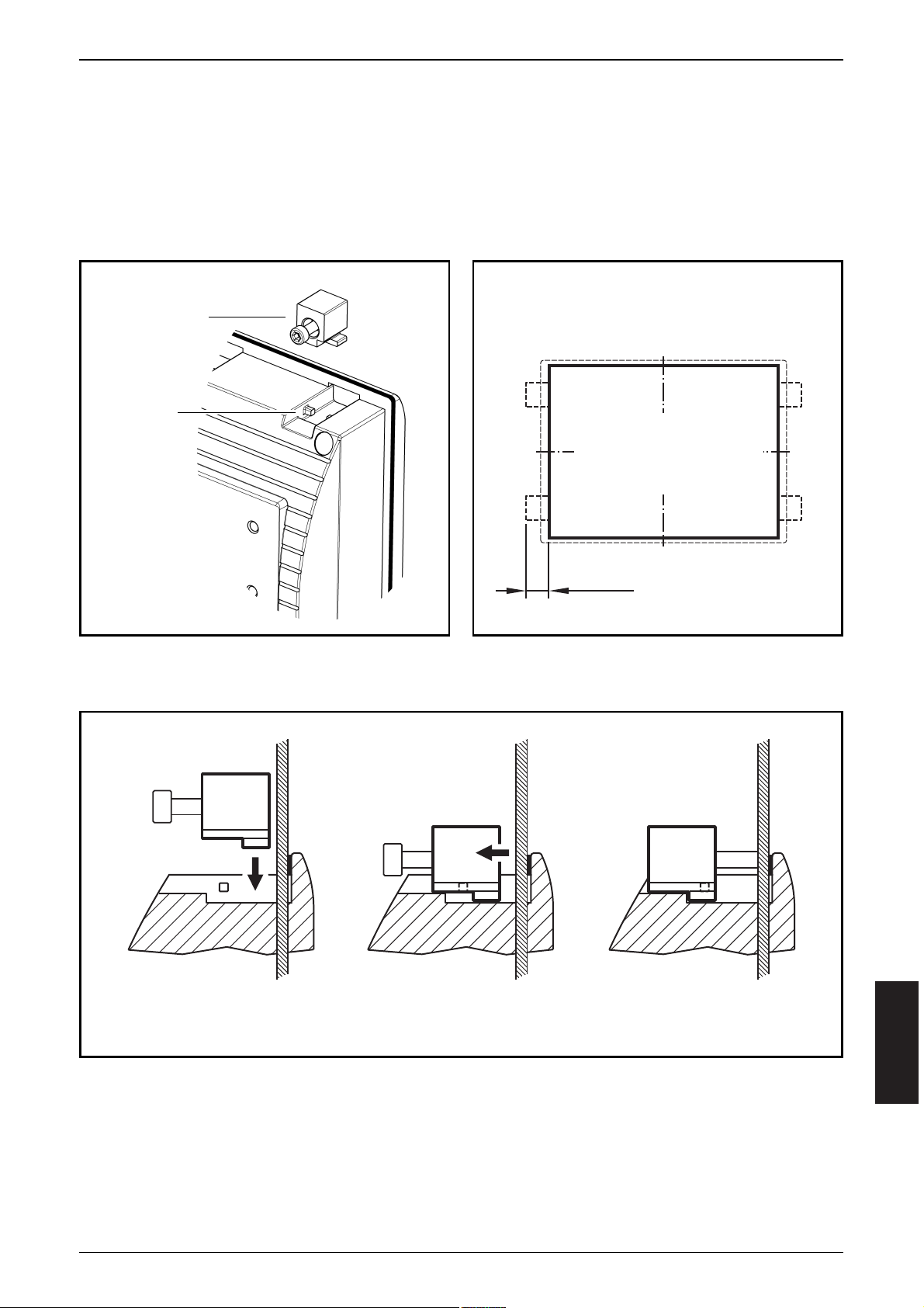
■ Schalttafeleinbau mit Haltewinkel (Fixing-Set EC1453)
Die Haltewinkel ermöglichen die waagerechte, senkrechte oder Überkopfmontage des Dialoggerätes.
Diese Einbauart ist geeignet für Materialstärken bis 8 mm.
Beachten Sie den benötigten Freiraum für die Haltewinkel!
Montageschritte:
min. 17
Ausschnitt
Führung
Haltewinkel in Führung legen, nach hinten schieben und Schrauben anziehen.
Haltewinkel
Freiraum
für Haltewinkel
Ausschnittmaße
s. technische Daten
(Anhang, Seite 12 ff)
Page 8
PROZESS- UND DIALOGGERÄT PDM 360 COMPACT
SEITE 8
■ Konsoleneinbau mit Befestigungsclips (Snap-in Set EC1452)
Diese Montageart vorzugsweise für eine aufliegende Geräteposition wählen, da
die Gerätebefestigung nur durch die Federkraft der Befestigungsclips erfolgt. Der
Neigungswinkel der Konsole darf 45° nicht überschreiten.
Bei der Wahl des Einbauortes beachten:
Zum Lösen der Befestigungsclips muss die Geräterückseite zugänglich sein.
Diese Einbauart ist geeignet für Materialstärken bis 5 mm.
Montageschritte:
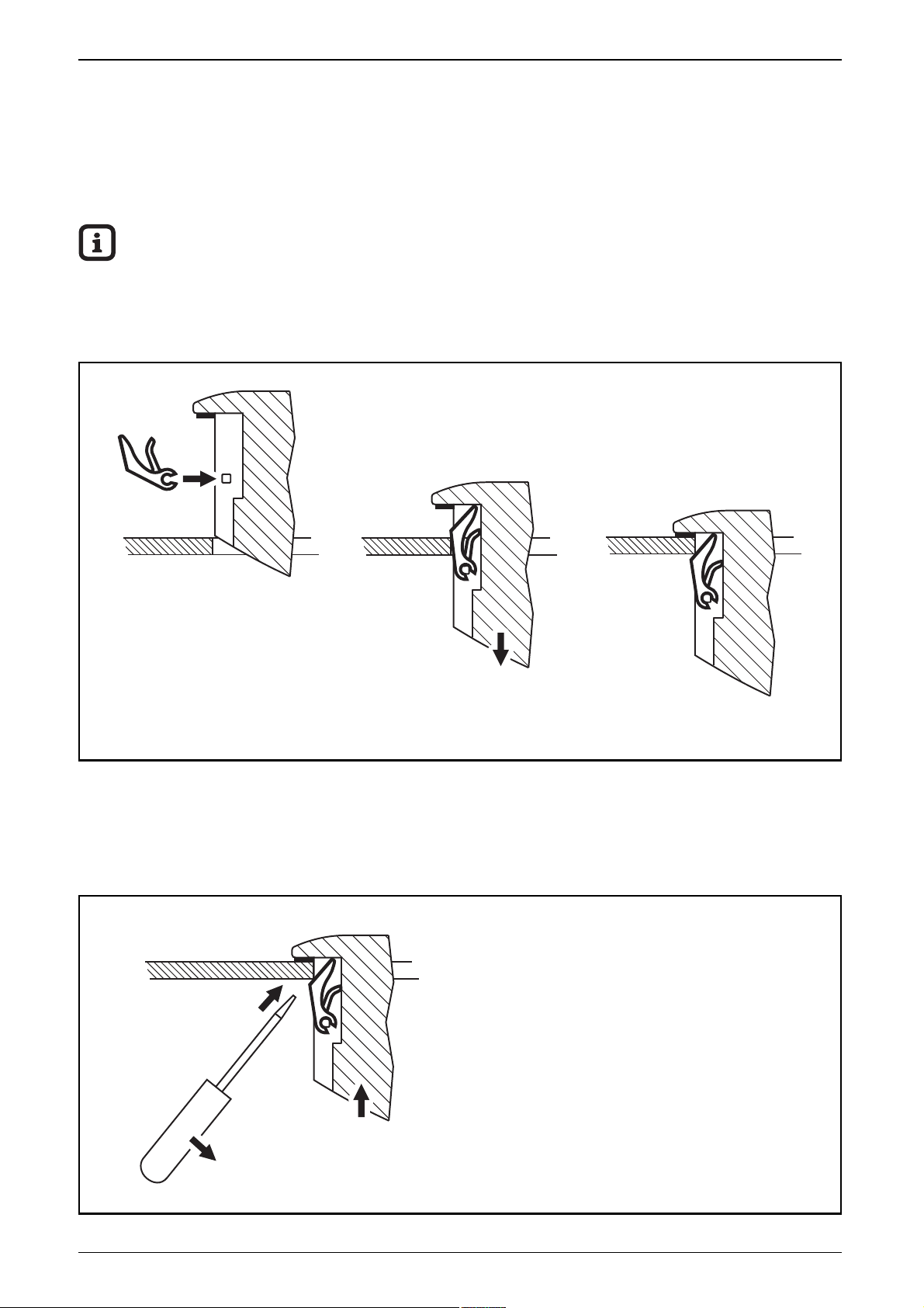
Entnahme des Gerätes aus der Konsole
Um mit einem Schraubendreher zwischen Konsolenauschnitt und Befestigungsclip zu gelangen, ist die geriffelte Abschrägung der Clips mit einer Nut versehen.
Clips einsetzen Gerät in den Ausschnitt drücken Endposition
Entnahmeschritte:
1. Auf der Geräterückseite Schraubendreher in die Nut der Clips einführen.
2. Schraubendreher anwinkeln und die
Federn der Clips zusammendrücken.
3. Gerät aus dem Ausschnitt heben.
Page 9

■ Aufbaumontage mit RAM®-Mount-System (EC1410...EC1414)
Mit den als Zubehör erhältlichen RAM®-Mount Bauteilen kann das Dialoggerät
als festmontiertes Standgerät genutzt werden. Zwei Kugelköpfe ermöglichen dabei eine variable Ausrichtung des Gerätes.
Die Geräterückseite ist für die Verschraubung der Montageplatte vorbereitet.
Weitere Informationen zu den verfügbaren RAM
®
-Mount Bauteilen unter:
➔ Datenblatt-Suche ➔ z.B. CR1055 ➔ Zubehör
www.ifm-electronic.com
DEUTSCH
PROZESS- UND DIALOGGERÄT PDM 360 COMPACT
SEITE 9
Kugelkopfaufnahme
Kugelkopfaufnahme
Montagearm
Montageplatte
Kugelkopf
Spannschraube
Page 10
PROZESS- UND DIALOGGERÄT PDM 360 COMPACT
SEITE 10
4. Elektrischer Anschluss
Um den elektrischen Störschutz sicherzustellen, muss das Gehäuse mit
GND verbunden werden (z.B. mit der Fahrzeugmasse).
Zum Schutz des gesamten Systems (Dialoggerät und Verkabelung) sind die
einzelnen Stromkreise abzusichern.
Die Anschlüsse der Versorgungsleitungen, Schnittstellen und Ein-/Ausgänge
(CR1056) erfolgen über M12-Steckverbinder auf der Geräterückseite.
Stecker 1 (Stift): Versorgung, CAN-Schnittstelle
Stecker 2 (Buchse): RS232-Schnittstelle, CAN-Schnittstelle
Stecker 3 (Buchse): Ein-/Ausgänge
Stecker 4 (Buchse): Ethernet
Anschlussbelegungen der Stecker siehe „Technische Daten“, CR1055 (Seite 13)
und CR1056 (Seite 15).
In EMV-kritschen Applikationen Signalleitungen abschirmen.
Um eine Korrosion zwischen den Steckverbindern und dem Zink-Druckguss-Gehäuse des Gerätes zu vermeiden, keine Kabeldosen mit Edelstahlverschraubung verwenden.
Die serielle Schnittstelle nur im spannungslosen Zustand verbinden oder
trennen.
Beim Trennen oder Verbinden der seriellen Schnittstelle unter Spannung
kann es zu undefinierten Zuständen kommen, die zu einer Schädigung des
RS-232 Treiberbausteins führen.
CR1056
4
2
3
CR1055
4
2
1
1
Bezeichnung Potential Stecker / Pin Sicherung
Versorgungsspannung Dialoggerät VBB
S
1/2 2 A
Versorgungsspannung Ausgänge (nur CR1056) VBB
O
3/5 2 A
Page 11

5. Wartung, Instandsetzung und Entsorgung
Das Prozess- und Dialoggerät ist wartungsfrei. Eine Instandsetzung des Gerätes
darf nur durch den Hersteller durchgeführt werden.
Die Entsorgung muss gemäß der nationalen Umweltvorschriften erfolgen.
DEUTSCH
PROZESS- UND DIALOGGERÄT PDM 360 COMPACT
SEITE 11
Page 12

PROZESS- UND DIALOGGERÄT PDM 360 COMPACT
SEITE 12
46,4
65,3
7
165
109
ifm electronic gmbh • Friedrichstraße 1 • 45128 Essen
28.01.2015
CR1055
Prozess- und Dialoggerät
PDM 360 compact
3,8" Monochrom-Display
3 frei programmierbare
hinterleuchtete
Funktionstasten
Ethernet
10...32 V DC
Technische Änderungen behalten wir uns ohne Ankündigung vor! CR1055 / Seite 1
Technische Daten Programmierbares Grafikdisplay zur Steuerung, Parametrierung
und Bedienung von mobilen Maschinen und Anlagen
Anzeige
Display FSTN, monochrom, transflektiv, grafikfähig
320 x 240 Pixel, 76,7 x 57,6 mm (3,8")
Hintergrundbeleuchtung LED
Kontrast 4096-stufig über Konfigurationsmenü einstellbar
Zeichensätze frei ladbar
Mechanische Daten
Montagevarianten • Einbaumontage
Abstützung von vorne durch am Deckel umlaufenden Kragen,
Befestigung durch Clips für Konsoleneinbau
oder Haltewinkel für Schalttafeleinbau
• Aufbaumontage
durch RAM
®
-Mount-System
(Montagezubehör nicht im Lieferumfang enthalten)
Abmessungen (B x H x T) 165 x 109 x 65,3 mm
Ausschnitt für Einbaumontage (B x H) 154 ± 0,5 x 10³ ± 0,5 mm
Gehäusematerial Zink-Druckguss, pulverbeschichtet (RAL 9006)
Frontfolie Polyester mit geprägten Tasten
Tasten 3 Stößeltasten mit taktiler Rückmeldung
hinterleuchtet (Helligkeit 0...100% einstellbar)
frei programmierbar (Softkey-Funktion)
Drehgeber mit mechanischer Drehdetektion, Rastung und
zentralem, mechanischen Drucktaster
Lebensdauer (Umdrehungen) > 100000
Schutzart IP 67
Betriebstemperatur -20...+70° C
Lagertemperatur -20...+70° C
Gewicht 1,21 kg
Elektrische Daten
Betriebsspannung 10...32 V DC
Stromaufnahme ≤ 180 mA (bei 24 V DC, ohne Last)
Kurzschluss-/Verpolungsschutz elektronisch
Prozessor Motorola PowerPC MPC823E, 50 Mhz
Programm-/Datenspeicher 8 Mbyte (Flash)
Datenspeicher 16 Mbyte (SDRAM)
Datenspeicher (retain) 1 Kbyte (FRAM)
Page 13

DEUTSCH
PROZESS- UND DIALOGGERÄT PDM 360 COMPACT
SEITE 13
ifm electronic gmbh • Friedrichstraße 1 • 45128 Essen
28.01.2015Technische Änderungen behalten wir uns ohne Ankündigung vor! CR1055 / Seite 2
CR1055 Technische Daten
Schnittstellen
CAN 1 Schnittstelle gem. ISO 11898 Vers. 2.0 B
Protokoll CANopen (CiA DS 301 V4), Profil DS 401
Baudrate: 50...500 kBit/s (Default 125 kBit/s)
Anschluss über 5-pol. M12 Steckverbinder
RS 232 Datenrate bis 115,2 kBaud
Anschluss über 5-pol. M12 Steckverbinder
Signale: RxD, TxD, GND
Ethernet Datenrate bis 10 Mbit/s
Anschluss über 4-pol. M12 Steckverbinder D-codiert (IEEE 802.3, 10BASE-T)
Software/Programmierung
Betriebssytem Embedded Linux 2.4
Programmierssystem CoDeSys Version 2.3
Grafische Funktionen durch integrierte Target-Visualisierung
Sonstige Ausstattung
Uhr –
Zulassungen/Prüfungen
CE-Zeichen DIN EN 61326, EN 61010-1: 2001
e1-Zeichen RL 2005/49/EG (Störaussendung und Störfestigkeit)
Störfestigkeit ISO 7637-2: 2004
Sonstige Prüfungen EN 60068 für Klima und Mechanik
Geräte-Rückansicht
Anschlussbelegung
*) galvanisch verbunden
Aufnahme für
RAM
®
-Mount-SystemM12 Steckverbinder
1
2
4
Stift
Buchse
Buchse
(D-codiert)
4
2
1
3
12
4
5
4
21
3
5
3
12
4
Aufnahme für
Befestigunsclip
oder Haltewinkel
Stecker 1
Versorgung, CAN*
Pin Potential
1 Shield
2 VBB
S
(10...32 V DC)
3 GND
4 CAN_H
5 CAN_L
Stecker 2
RS232, CAN*
Pin Potential
1 RS232_TxD
2 RS232_RxD
3 GND
4 CAN_H
5 CAN_L
Stecker 3
(nicht belegt)
–
–
Stecker 4
Ethernet
Pin Potential
1 TxD+
2 RxD+
3 TxD–
4 RxD–
Page 14

PROZESS- UND DIALOGGERÄT PDM 360 COMPACT
SEITE 14
46,4
65,3
7
165
109
ifm electronic gmbh • Friedrichstraße 1 • 45128 Essen
28.01.2015
CR1056
Prozess- und Dialoggerät
PDM 360 compact
3,8" Monochrom-Display
3 frei programmierbare
hinterleuchtete
Funktionstasten
Ethernet, Echtzeituhr
2 Eingänge / 2 Ausgänge
10...32 V DC
Technische Änderungen behalten wir uns ohne Ankündigung vor! CR1056 / Seite 1
Technische Daten Programmierbares Grafikdisplay zur Steuerung, Parametrierung
und Bedienung von mobilen Maschinen und Anlagen
Anzeige
Display FSTN, monochrom, transflektiv, grafikfähig
320 x 240 Pixel, 76,7 x 57,6 mm (3,8")
Hintergrundbeleuchtung LED
Kontrast 4096-stufig über Konfigurationsmenü einstellbar
Zeichensätze frei ladbar
Mechanische Daten
Montagevarianten • Einbaumontage
Abstützung von vorne durch am Deckel umlaufenden Kragen,
Befestigung durch Clips für Konsoleneinbau
oder Haltewinkel für Schalttafeleinbau
• Aufbaumontage
durch RAM
®
-Mount-System
(Montagezubehör nicht im Lieferumfang enthalten)
Abmessungen (B x H x T) 165 x 109 x 65,3 mm
Ausschnitt für Einbaumontage (B x H) 154 ± 0,5 x 10³ ± 0,5 mm
Gehäusematerial Zink-Druckguss, pulverbeschichtet (RAL 9006)
Frontfolie Polyester mit geprägten Tasten
Tasten 3 Stößeltasten mit taktiler Rückmeldung
hinterleuchtet (Helligkeit 0...100% einstellbar)
frei programmierbar (Softkey-Funktion)
Drehgeber mit mechanischer Drehdetektion, Rastung und
zentralem, mechanischen Drucktaster
Lebensdauer (Umdrehungen) > 100000
Schutzart IP 67
Betriebstemperatur -20...+70° C
Lagertemperatur -20...+70° C
Gewicht 1,22 kg
Elektrische Daten
Betriebsspannung 10...32 V DC
Stromaufnahme ≤ 180 mA (bei 24 V DC, ohne Last)
Kurzschluss-/Verpolungsschutz elektronisch
Prozessor Motorola PowerPC MPC823E, 50 Mhz
Programm-/Datenspeicher 8 Mbyte (Flash)
Datenspeicher 16 Mbyte (SDRAM)
Datenspeicher (retain) 1 Kbyte (FRAM)
Page 15

DEUTSCH
PROZESS- UND DIALOGGERÄT PDM 360 COMPACT
SEITE 15
gy
ifm electronic gmbh • Friedrichstraße 1 • 45128 Essen
28.01.2015Technische Änderungen behalten wir uns ohne Ankündigung vor! CR1056 / Seite 2
CR1056 Technische Daten
Schnittstellen
CAN 1 Schnittstelle gem. ISO 11898 Vers. 2.0 B
Protokoll CANopen (CiA DS 301 V4), Profil DS 401
Baudrate: 50...500 kBit/s (Default 125 kBit/s)
Anschluss über 5-pol. M12 Steckverbinder
RS 232 Datenrate bis 115,2 kBaud
Anschluss über 5-pol. M12 Steckverbinder
Signale: RxD, TxD, GND
Ethernet Datenrate bis 10 Mbit/s
Anschluss über 4-pol. M12 Steckverbinder D-codiert (IEEE 802.3, 10BASE-T)
Software/Programmierung
Betriebssytem Embedded Linux 2.4
Programmierssystem CoDeSys Version 2.3
Grafische Funktionen durch integrierte Target-Visualisierung
Sonstige Ausstattung
Uhr Realtime-Clock (Li-Batterie gepuffert, 10 Jahre Lebensdauer)
Zulassungen/Prüfungen
CE-Zeichen DIN EN 61326, EN 61010-1
E1-Zeichen gemäß UN/ECE-R10 (Störaussendung und Störfestigkeit)
Störfestigkeit ISO 7637-2
Sonstige Prüfungen EN 60068 für Klima und Mechanik
Geräte-Rückansicht
Anschlussbelegung
*) galvanisch verbunden
Aufnahme für
RAM
®
-Mount-SystemM12 Steckverbinder
1
2/3
4
Stift
Buchse
Buchse
(D-codiert)
4
2
1
3
3
12
4
5
4
21
3
5
3
12
4
Aufnahme für
Befestigunsclip
oder Haltewinkel
Stecker 1
Versorgung, CAN*
Pin Potential
1 Shield
2 VBB
S
(10...32 V DC)
3 GND
4 CAN_H
5 CAN_L
Stecker 2
RS232, CAN*
Pin Potential
1 RS232_TxD
2 RS232_RxD
3 GND
4 CAN_H
5 CAN_L
Stecker 3
Ein-/Ausgänge
Pin Potential
1 IN 1
2 IN 2
3 OUT 1
4 OUT 2
5 VBB
O
Stecker 4
Ethernet
Pin Potential
1 TxD+
2 RxD+
3 TxD–
4 RxD–
Page 16

PROZESS- UND DIALOGGERÄT PDM 360 COMPACT
SEITE 16
ifm electronic gmbh • Friedrichstraße 1 • 45128 Essen
28.01.2015Technische Änderungen behalten wir uns ohne Ankündigung vor! CR1056 / Seite 3
CR1056 Kennwerte der Ein-/Ausgänge
Eingänge
%IX0.00...01 (B
L
) ■ Digitaleingänge für positive Gebersignale
konfigurierbar als... Einschaltpegel 0,7 U
B
Ausschaltpegel 0,4 U
B
Eingangswiderstand 3,2 kΩ
Eingangsfrequenz max. 50 Hz
Ausgänge
%QX0.00...01 (B
H
) ■ Halbleiterausgänge
konfigurierbar als... plusschaltend (High-Side), kurzschluss- und überlastfest
Schaltspannung 10...32 V DC
Schaltstrom max. 0,5 A (je Ausgang)
Ausgangsfrequenz max. 100 Hz (lastabhängig)
Page 17

ENGLISH
PROCESS AND DIALOGUE MODULE PDM 360 COMPACT
PAGE 17
Page 18

Safety instructions
This description is part of the unit. It contains texts and drawings
concerning the correct handling of the module and must be read before installation or use.
Observe the information of the description. Non-observance of the notes, operation which is not in accordance with use as prescribed below, wrong installation
or handling can result in serious harm concerning the safety of persons and
plant.
The instructions are for authorised persons according to the EMC and low voltage guidelines. The process and dialogue modules must be installed and commissioned by a skilled electrician (programmer or service technician).
If the unit is not supplied by the mobile on-board system (12/24 V battery operation) it must be ensured that the external voltage is generated and supplied according to the criteria for safety extra-low voltage (SELV) as this is supplied without further measures to the connected controller, the sensors, and the actuators.
The wiring of all signals in connection with the SELV circuit of the unit must also
comply with the SELV criteria (safe extra-low voltage, safe electrical separation
from other electric circuits).
If the supplied SELV voltage has an external connection to ground (SELV becomes
PELV) the responsibility lies with the user and the respective national regulations
for installation must be complied with. All statements in these operating instructions refer to the unit the SELV voltage of which is not grounded.
The connectors may only be supplied with the signals indicated in the technical
data or on the unit label and only the approved accessories of ifm electronic
gmbh may be connected.
The unit can be operated within a wide temperature range according to the technical specification indicated below. Due to the additional self-heating the housing
walls can have high perceptible temperatures when touched in hot environments.
In case of malfunctions or uncertainties please contact the manufacturer. Tampering with the unit can lead to considerable risks for the safety of persons and
plant. It is not permitted and leads to the exclusion of any liability and warranty
claims.
Electromagnetic compatibility
This is a class A installation. It can cause radio interference in domestic areas.
In this case the operator is requested to take appropriate measures.
PROCESS AND DIALOGUE MODULE PDM 360 COMPACT
PAGE 18
Page 19

Contents
1. Function and features . . . . . . . . . . . . . . . . . . . . . . . . . . . . . . page 20
Features at a glance . . . . . . . . . . . . . . . . . . . . . . . . . . . . . . . page 20
2. Programming . . . . . . . . . . . . . . . . . . . . . . . . . . . . . . . . . . . page 21
Configuration and online help. . . . . . . . . . . . . . . . . . . . . . . . page 21
3. Mounting
Mounting accessories . . . . . . . . . . . . . . . . . . . . . . . . . . . . . . page 22
Seal/vibration absorber . . . . . . . . . . . . . . . . . . . . . . . . . . . . . page 22
Control cabinet mounting with mounting brackets (fixing set). page 23
Panel mounting with clips (snap-in set) . . . . . . . . . . . . . . . . . page 24
Surface mounting with RAM®mount system . . . . . . . . . . . . . page 25
4. Electrical connection . . . . . . . . . . . . . . . . . . . . . . . . . . . . . . . page 26
5. Maintenance, repair and disposal . . . . . . . . . . . . . . . . . . . . . page 27
Annex
Technical data CR1055
Dimension . . . . . . . . . . . . . . . . . . . . . . . . . . . . . . . . . . . . . . page 28
Display. . . . . . . . . . . . . . . . . . . . . . . . . . . . . . . . . . . . . . . . . page 28
Mechanical data . . . . . . . . . . . . . . . . . . . . . . . . . . . . . . . . . . page 28
Electrical data. . . . . . . . . . . . . . . . . . . . . . . . . . . . . . . . . . . . page 28
Interfaces . . . . . . . . . . . . . . . . . . . . . . . . . . . . . . . . . . . . . . . page 29
Software / Programming . . . . . . . . . . . . . . . . . . . . . . . . . . . . page 29
Other features . . . . . . . . . . . . . . . . . . . . . . . . . . . . . . . . . . . page 29
Tests / Approvals. . . . . . . . . . . . . . . . . . . . . . . . . . . . . . . . . . page 29
Wiring . . . . . . . . . . . . . . . . . . . . . . . . . . . . . . . . . . . . . . . . . page 29
Technical data CR1056
Dimension . . . . . . . . . . . . . . . . . . . . . . . . . . . . . . . . . . . . . . page 30
Display. . . . . . . . . . . . . . . . . . . . . . . . . . . . . . . . . . . . . . . . . page 30
Mechanical data . . . . . . . . . . . . . . . . . . . . . . . . . . . . . . . . . . page 30
Electrical data. . . . . . . . . . . . . . . . . . . . . . . . . . . . . . . . . . . . page 30
Interfaces . . . . . . . . . . . . . . . . . . . . . . . . . . . . . . . . . . . . . . . page 31
Software / Programming . . . . . . . . . . . . . . . . . . . . . . . . . . . . page 31
Other features . . . . . . . . . . . . . . . . . . . . . . . . . . . . . . . . . . . page 31
Tests / Approvals. . . . . . . . . . . . . . . . . . . . . . . . . . . . . . . . . . page 31
Wiring . . . . . . . . . . . . . . . . . . . . . . . . . . . . . . . . . . . . . . . . . page 31
Characteristics of the inputs / outputs . . . . . . . . . . . . . . . . . . page 32
ENGLISH
PROCESS AND DIALOGUE MODULE PDM 360 COMPACT
PAGE 19
Page 20

1. Function and features
The process and dialogue module PDM360 compact compact is a programmable
graphic display for controlling, parameter-setting and operation of mobile machines and plants.
Communication with other system components, e.g. decentralised I/O modules, is
handled via a CAN interface using the CANopen protocol.
The Ethernet and RS-232 interface as well as the inputs/outputs (only CR1056)
form a universal platform for networking and communication with other units.
The process and dialogue module PDM360 compact is not approved for
safety-related tasks in the sense of the safety of persons.
Features at a glance
• 3.8" display (320 x 240 pixels)
• 3 backlit function keys, freely programmable
• 1 encoder with central mechanical pushbutton
• Closed metal housing (IP 67) suitable for panel mounting and surface
mounting outside or in the cabin
• Freely programmable in accordance with IEC 61131-3 with target visualisation
• 32-bit controller and Embedded Linux operating system
• CAN interface with CANopen protocol
• Ethernet and RS-232 interface
PROCESS AND DIALOGUE MODULE PDM 360 COMPACT
PAGE 20
¹)Downloads with registration
Page 21

2. Programming
The application software can be easily created by the user with the ifm programming system CoDeSys (version 2.3.5 or higher) according to IEC 61131-3.
As download file (HTML file) the ifm online help CoDeSys V2.3 is available on the
internet:
➔ Data sheet direct ➔ CR105... ➔ Download/Software
1)
The user is responsible for the safe functioning of the application programs
which he creates himself. If necessary, he must additionally obtain an approval according to the corresponding national regulations by the corresponding
testing and supervisory organisations.
Configuration and online help
As delivered the PDM360 compact is prepared for programming with CoDeSys
version 2.3.5 or higher.
Pressing the F1 and F2 keys simultaneously at power on opens the configuration
menu:
You can find more information about programming and use in the PDM online
help on the CD-ROM "ecolog software, tools and documentation" (art. no.
CP9008).
The PDM online help contains descriptions for the following topics:
• PDM360 device setup
• Communication and programming interfaces
• Creation of new projects
• Libraries
• PDM360 device update.
www.ifm-electronic.com
ENGLISH
PROCESS AND DIALOGUE MODULE PDM 360 COMPACT
PAGE 21
The PDM360 setup allows settings
for communication and file management.
The menu items are selected by
turning the encoder, pressing the
encoder pushbutton the respective
submenu will appear.
After leaving the setup a project can
be loaded.
Libraries (.lib) are available for the
use of the operating elements, interfaces and other internal functions
of the device. They have to be integrated into the application program.
screenshot CR1056
Page 22

3. Mounting
■ Mounting accessories
The unit is supplied without mounting accessories.
Depending on the intended location and type of mounting the following mounting accessories are available:
• EC1450, seal/vibration absorber for panel/control cabinet mounting
• EC1452, snap-in set for panel mounting*
• EC1453, fixing set for control cabinet mounting*
• EC1410...EC1414, RAM®mount system for surface mounting
You can find more information about the available accessories at:
➔ Data sheet direct ➔ e.g. CR1056 ➔ Accessories
*) Use the snap-in set (EC1452) and the fixing set (EC1453) only in conjunction
with the seal/vibration absorber (EC1450).
■ Seal/vibration absorber
Slide the seal/vibration absorber over the unit from the back.
www.ifm-electronic.com
PROCESS AND DIALOGUE MODULE PDM 360 COMPACT
PAGE 22
EC1450
Seal/vibration absorber for PDM360 smart,
PDM360 compact
the polyester film is
on the dialogue unit
Page 23

■ Control cabinet mounting with mounting brackets (fixing set EC1453)
The mounting brackets enable the horizontal, vertical or upside-down mounting
of the dialogue module. This type of mounting is suited for materials with a
thickness of max. 8 mm.
Please take into account the required clearance space for the mounting brackets!
Mounting steps:
ENGLISH
PROCESS AND DIALOGUE MODULE PDM 360 COMPACT
PAGE 23
Move mounting bracket into guide, slide it backwards and tighten the screws.
min. 17
Ausschnitt
guidance
mounting
bracket
Clearance space
for mounting brackets
For the cutout dimen-
sions see the technical
data
(attachment, page 28
onwards)
Page 24

■ Panel mounting with clips (snap-in set EC1452)
Preferably select this type of mounting when the unit is to be laid in the horizontal position as it is only held by the force of the clips.
The angle of inclination of the panel must not exceed 45°.
Note when selecting the mounting location:
To loosen the clips the back of the unit must be accessible.
This type of mounting is suited for materials with a thickness of max. 5 mm.
Mounting steps:
Removing the unit from the panel
To insert the screwdriver between the cut-out of the panel and the clip, the
grooved chamfer of the clips must be fitted with a slot.
PROCESS AND DIALOGUE MODULE PDM 360 COMPACT
PAGE 24
Insert clips Press the unit into the cutout end position
Steps for removal:
1. Insert the screwdriver into the slot of
the clips on the back.
2. Angle the screwdriver and compress
the springs of the clips.
3. Remove the unit from the cutout.
front
back
Page 25

■ Surface mounting with RAM®mount system (EC1410...EC1414)
Using the RAM®mount components, available as accessories, the dialogue unit
can be used as a firmly mounted desktop unit. Two balls allow variable orientation of the unit.
The back of the unit has been prepared for fixing the mounting plate.
You can find more information about the available RAM
®
mount components at:
➔ Data sheet direct ➔ e.g. CR1055 ➔ Accessories
www.ifm-electronic.com
ENGLISH
PROCESS AND DIALOGUE MODULE PDM 360 COMPACT
PAGE 25
ball locator
ball locator
mounting arm
mounting plate
ball
clamp screw
Page 26

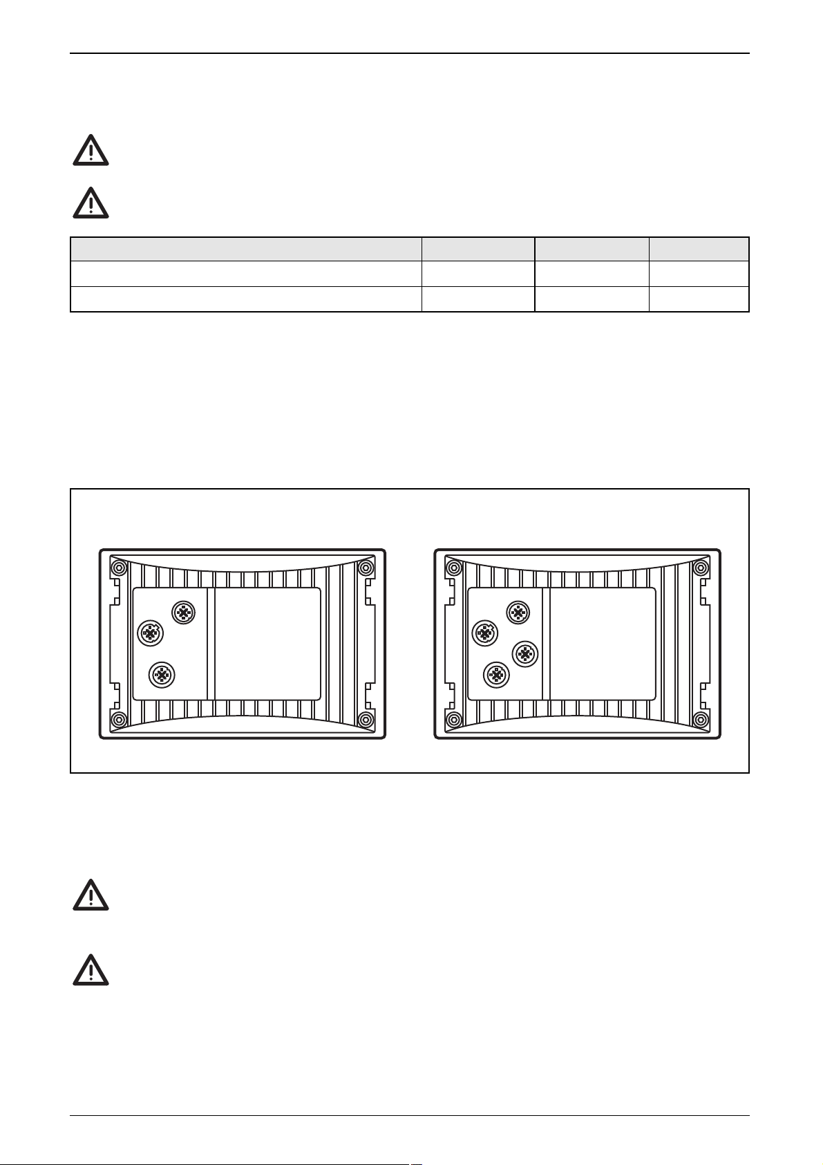
4. Electrical connection
To guarantee the electrical interference protection of the module, the
housing must be connected to GND (e.g. to the ground of the vehicle).
To protect the whole system (dialogue module and wiring ) the individual
electric circuits must be protected.
The supply cables, interfaces and inputs/outputs (CR1056) are connected via M12
connectors on the back of the unit.
Connector 1 (male): supply, CAN interface
Connector 2 (female): RS232 interface, CAN interface
Connector 3 (female): inputs / outputs
Connector 4 (female): Ethernet
For the pin connection of the connectors see the "technical data", CR1055 (page
29) and CR1056 (page 31).
Screen signal cables in EMC-critical applications.
To prevent corrosion between the connectors and the diecast zinc housing
of the unit, do not use any sockets with stainless steel fitting.
Do not connect or disconnect the serial interface while live.
Connecting or disconnecting the serial interface while live can lead to undefined states, causing damage to the RS-232 driver module.
PROCESS AND DIALOGUE MODULE PDM 360 COMPACT
PAGE 26
Description Potential Connector / Pin Fuse
Power supply dialogue module VBB
S
1/2 2 A
Power supply outputs (only CR1056) VBB
O
3/5 2 A
CR1056
4
2
3
CR1055
4
2
1
1
Page 27

5. Maintenance, repair and disposal
The process and dialogue module is maintenance-free and may only be repaired
by the manufacturer. The unit must be disposed of in accordance with the national environmental regulations.
ENGLISH
PROCESS AND DIALOGUE MODULE PDM 360 COMPACT
PAGE 27
Page 28

PROCESS AND DIALOGUE MODULE PDM 360 COMPACT
PAGE 28
46,4
65,3
7
165
109
ifm electronic gmbh • Friedrichstraße 1 • 45128 Essen
28.01.2015
CR1055
Process and dialogue
module
PDM 360 compact
3.8" monochrome display
3 freely programmable
backlit function keys
Ethernet
10...32 V DC
We reserve the right to make technical alterations without prior notice. CR1055 / page 1
Technical data Programmable graphic display for controlling, parameter-setting
and operation of mobile machines and plants
Display
Display FSTN, monochrome, transflective, with graphics capabilities,
320 x 240 pixels, 76.7 x 57.6 mm (3.8")
Background illumination LED
Contrast adjustable in 4096 steps via the configuration menu
Sets of characters can be uploaded individually
Mechanical data
Mounting variants • panel mounting
support from the front via lip around the cover,
fixing with clips when mounted into a panel
or mounting brackets when mounted into a control cabinet
• surface mounting
via RAM
®
mount system
(mounting accessories not included)
Dimensions (W x H x D) 165 x 109 x 65.3 mm
Cutout for panel mounting (W x H) 154 ± 0.5 x 10³ ± 0.5 mm
Housing material die-cast zinc, powder coated (RAL 9006)
Protective film polyester with embossed keys
Keys 3 short-stroke keys, with tactile feedback
backlit (brightness 0...100% adjustable)
freely programmable (softkey function)
Encoder with mechanical rotation detection, latching
and central mechanical pushbutton
Lifetime (revolutions) > 100000
Protection IP 67
Operating temperature -20...+70° C
Storage temperature -20...+70° C
Weight 1.21 kg
Electrical data
Operating voltage 10...32 V DC
Current consumption ≤ 180 mA (at 24 V DC without external load)
Short-circuit / reverse polarity protection
electronic
Processor Motorola PowerPC MPC823E, 50 MHz
Program and data memory 8 Mbytes (Flash)
Data memory 16 Mbytes SDRAM
Data memory (retain) 1 Kbytes (FRAM)
Page 29

ENGLISH
PROCESS AND DIALOGUE MODULE PDM 360 COMPACT
PAGE 29
y
ifm electronic gmbh • Friedrichstraße 1 • 45128 Essen
28.01.2015We reserve the right to make technical alterations without prior notice. CR1055 / page 2
CR1055 Technical data
Interfaces
CAN 1 interface in accordance with ISO 11898 version 2.0 B
protocol CANopen (CiA DS 301 V4), profile DS 401
baud rate: 50...500 Kbits/s (default 125 Kbits/s)
connection via 5-pole M12 connector
RS 232 transmission rate up to 115.2 Kbaud
connection via 5-pole M12 connector
signals: RxD, TxD, GND
Ethernet transmission rate up to 10 Mbits/s
connection via 4-pole M12 connector D coded (IEEE 802,3, 10 BASE-T)
Software/Programming
Operating system embedded Linux 2.4
Programming system CoDeSys version 2.3
Graphic functions via integrated target visualisation
Other features
Clock –
Tests/Approvals
CE marking DIN EN 61326, EN 61010-1
E1 marking according to UN/ECE-R10 (noise emission and noise immunity)
Noise immunity ISO 7637-2
Other tests EN 60068 for climatic and mechanical testing
Back of the unit
Wiring
*) electrically connected
Aufnahme für
RAM
®
-Mount-SystemM12 Steckverbinder
1
2
4
Stift
Buchse
Buchse
(D-codiert)
4
2
1
3
12
4
5
4
21
3
5
3
12
4
Aufnahme für
Befestigunsclip
oder Haltewinkel
Connector 1
Supply, CAN*
Pin Potential
1 Shield
2 VBB
S
(10...32 V DC)
3 GND
4 CAN_H
5 CAN_L
Connector 2
RS232, CAN*
Pin Potential
1 RS232_TxD
2 RS232_RxD
3 GND
4 CAN_H
5 CAN_L
Connector 3
(not used)
–
–
Connector 4
Ethernet
Pin Potential
1 TxD+
2 RxD+
3 TxD–
4 RxD–
locator for clip
or bracket
locator for the
RAM
®
mount system
M12 connector
male
female
female
(D coded)
Page 30

PROCESS AND DIALOGUE MODULE PDM 360 COMPACT
PAGE 30
46,4
65,3
7
165
109
ifm electronic gmbh • Friedrichstraße 1 • 45128 Essen
28.01.2015
CR1056
Process and dialogue
module
PDM 360 compact
3.8" monochrome display
3 freely programmable
backlit function keys
Ethernet, realtime clock
2 inputs / 2 outputs
10...32 V DC
We reserve the right to make technical alterations without prior notice. CR1056 / page 1
Technical data Programmable graphic display for controlling, parameter-setting
and operation of mobile machines and plants
Display
Display FSTN, monochrome, transflective, with graphics capabilities,
320 x 240 pixels, 76.7 x 57.6 mm (3.8")
Background illumination LED
Contrast adjustable in 4096 steps via the configuration menu
Sets of characters can be uploaded individually
Mechanical data
Mounting variants • panel mounting
support from the front via lip around the cover,
fixing with clips when mounted into a panel
or mounting brackets when mounted into a control cabinet
• surface mounting
via RAM
®
mount system
(mounting accessories not included)
Dimensions (W x H x D) 165 x 109 x 65.3 mm
Cutout for panel mounting (W x H) 154 ± 0.5 x 10³ ± 0.5 mm
Housing material die-cast zinc, powder coated (RAL 9006)
Protective film polyester with embossed keys
Keys 3 short-stroke keys, with tactile feedback
backlit (brightness 0...100% adjustable)
freely programmable (softkey function)
Encoder with mechanical rotation detection, latching
and central mechanical pushbutton
Lifetime (revolutions) > 100000
Protection IP 67
Operating temperature -20...+70° C
Storage temperature -20...+70° C
Weight 1.22 kg
Electrical data
Operating voltage 10...32 V DC
Current consumption ≤ 180 mA (at 24 V DC without external load)
Short-circuit / reverse polarity protection
electronic
Processor Motorola PowerPC MPC823E, 50 MHz
Program and data memory 8 Mbytes (Flash)
Data memory 16 Mbytes (SDRAM)
Data memory (retain) 1 Kbytes (FRAM)
Page 31

ENGLISH
PROCESS AND DIALOGUE MODULE PDM 360 COMPACT
PAGE 31
ifm electronic gmbh • Friedrichstraße 1 • 45128 Essen
28.01.2015We reserve the right to make technical alterations without prior notice. CR1056 / page 2
CR1056 Technical data
Interfaces
CAN 1 interface in accordance with ISO 11898 version 2.0 B
protocol CANopen (CiA DS 301 V4), profile DS 401
baud rate: 50...500 Kbits/s (default 125 Kbits/s)
connection via 5-pole M12 connector
RS 232 transmission rate up to 115.2 Kbaud
connection via 5-pole M12 connector
signals: RxD, TxD, GND
Ethernet transmission rate up to 10 Mbits/s
connection via 4-pole M12 connector D coded (IEEE 802,3, 10 BASE-T)
Software/Programming
Operating system embedded Linux 2.4
Programming system CoDeSys version 2.3
Graphic functions via integrated target visualisation
Other features
Clock realtime clock (Li battery buffered, 10 years lifetime)
Tests/Approvals
CE marking DIN EN 61326, EN 61010-1
E1 marking according to UN/ECE-R10 (noise emission and noise immunity)
Noise immunity ISO 7637-2
Other tests EN 60068 for climatic and mechanical testing
Back of the unit
Wiring
*) electrically connected
Aufnahme für
RAM
®
-Mount-SystemM12 Steckverbinder
1
2/3
4
Stift
Buchse
Buchse
(D-codiert)
4
2
1
3
3
12
4
5
4
21
3
5
3
12
4
Aufnahme für
Befestigunsclip
oder Haltewinkel
Connector 1
Supply, CAN
Pin Potential
1 Shield
2 VBB
S
(10...32 V DC)
3 GND
4 CAN_H
5 CAN_L
Connector 2
RS232, CAN
Pin Potential
1 RS232_TxD
2 RS232_RxD
3 GND
4 CAN_H
5 CAN_L
Connector 3
Inputs, outputs
Pin Potential
1 IN 1
2 IN 2
3 OUT 1
4 OUT 2
5 VBB
O
Connector 4
Ethernet
Pin Potential
1 TxD+
2 RxD+
3 TxD–
4 RxD–
locator for clip
or bracket
locator for the
RAM
®
mount system
M12 connector
male
female
female
(D coded)
Page 32

PROCESS AND DIALOGUE MODULE PDM 360 COMPACT
PAGE 32
ifm electronic gmbh • Friedrichstraße 1 • 45128 Essen
28.01.2015We reserve the right to make technical alterations without prior notice. CR1056 / page 3
CR1056 Characteristics of the inputs / outputs
Inputs
%IX0.00...01 (B
L
) ■ Digital inputs for positive sensor signals
can be configured as ... switch-on level 0.7 U
B
switch-off level 0.4 U
B
input resistance 3.2 kΩ
input frequency max. 50 Hz
Outputs
%QX0.00...01 (B
H
) ■ Semiconductor outputs
can be configured as ... positive switching (high side), short-circuit and overload protected
switching voltage 10...32 V DC
switching current max. 0.5 A (per output)
output frequency max. 100 Hz (depending on the load)
 Loading...