

Page 1
Programming Manual
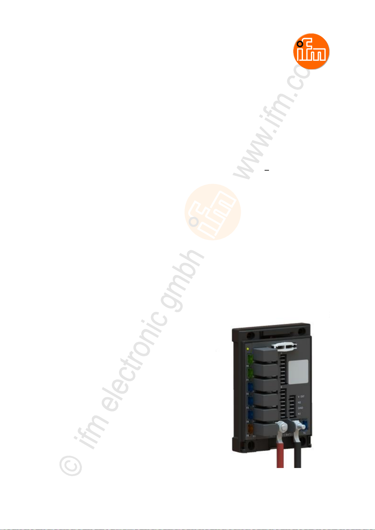
BasicController relay
CR0431
Runtime system V03.03.00
CODESYS® > v2.3.9.33 (< v3.0)
English
739
1039 / 02
05 / 2018
1
Page 2

ifm Programming Manual BasicController relay CR0431 v03.03.00 05 / 2018
Contents
Contents
1 About this manual 4
1.1 Copyright .............................................................................................................................. 4
1.2 Overview: documentation modules for CR0431 .................................................................. 5
1.3 What do the symbols and formats mean? ........................................................................... 6
1.4 How is this documentation structured? ................................................................................ 7
1.5 History of the instructions (CR043n) .................................................................................. 7
2 Safety instructions 8
2.1 Please note .......................................................................................................................... 8
2.2 What previous knowledge is required? ................................................................................ 8
2.3 Start-up behaviour of the controller...................................................................................... 9
2.4 Notes: serial number ............................................................................................................ 9
3 System description 10
3.1 Information about the device ..............................................................................................10
3.2 Hardware description .........................................................................................................11
3.2.1 Hardware structure ..................................................................................................................... 11
3.2.2 Inputs (technology) ..................................................................................................................... 14
3.2.3 Outputs (technology) .................................................................................................................. 18
3.2.4 Note on wiring ............................................................................................................................ 20
3.2.5 Safety instructions about Reed relays ........................................................................................ 20
3.2.6 Status-LED ................................................................................................................................. 21
3.3 Interface description ...........................................................................................................22
3.3.1 CAN interfaces ........................................................................................................................... 22
3.4 Software description ..........................................................................................................23
3.4.1 Software modules for the device ................................................................................................ 23
3.4.2 Programming notes for CODESYS projects ............................................................................... 26
3.4.3 Operating states ......................................................................................................................... 29
3.4.4 Performance limits of the device ................................................................................................ 31
4 Configurations 34
4.1 Set up the runtime system .................................................................................................34
4.1.1 Reinstall the runtime system ...................................................................................................... 35
4.1.2 Update the runtime system ......................................................................................................... 36
4.1.3 Verify the installation .................................................................................................................. 36
4.2 Set up the programming system ........................................................................................37
4.2.1 Set up the programming system manually ................................................................................. 37
4.2.2 Set up the programming system via templates ........................................................................... 41
4.3 Function configuration in general .......................................................................................41
4.3.1 System variables ........................................................................................................................ 41
4.4 Function configuration of the inputs and outputs ...............................................................42
4.4.1 Configuration of the inputs (default setting) ................................................................................ 42
4.4.2 Configure inputs ......................................................................................................................... 43
4.4.3 Configure outputs ....................................................................................................................... 48
4.5 Variables ............................................................................................................................50
4.5.1 Retain variables .......................................................................................................................... 51
4.5.2 Network variables ....................................................................................................................... 52
5 ifm function elements 53
5.1 ifm libraries for the device CR0431 ....................................................................................53
5.1.1 Library ifm_CR0431_V03yyzz.LIB .............................................................................................. 54
2
Page 3

ifm Programming Manual BasicController relay CR0431 v03.03.00 05 / 2018
Contents
5.1.2 Library ifm_CR0431_util_V03yyzz.LIB ....................................................................................... 55
5.1.3 Library ifm_RAWCan_NT_Vxxyyzz.LIB...................................................................................... 55
5.1.4 Library ifm_CANopen_NT_Vxxyyzz.LIB ..................................................................................... 56
5.1.5 Library ifm_J1939_NT_Vxxyyzz.LIB ........................................................................................... 57
5.2 ifm function elements for the device CR0431 ....................................................................58
5.2.1 Function element outputs ........................................................................................................... 59
5.2.2 Function elements: RAW-CAN (Layer 2) ................................................................ .................... 60
5.2.3 Function elements: CANopen ..................................................................................................... 86
5.2.4 Function elements: SAE J1939 ................................................................................................ 132
5.2.5 Function elements: processing input values ............................................................................. 164
5.2.6 Function elements: output functions ......................................................................................... 175
5.2.7 Function elements: system ....................................................................................................... 182
6 Diagnosis and error handling 200
6.1 Diagnosis .........................................................................................................................200
6.2 Fault .................................................................................................................................200
6.3 Response to system errors ..............................................................................................200
6.3.1 Example process for response to an error message ................................................................ 201
6.4 CAN / CANopen: errors and error handling .....................................................................201
7 Appendix 202
7.1 System flags .....................................................................................................................202
7.1.1 System flags: voltages.............................................................................................................. 203
7.1.2 System flags: inputs and outputs .............................................................................................. 203
7.1.3 System flags: system ............................................................................................................... 203
7.2 Address assignment and I/O operating modes ................................................................204
7.2.1 Address assignment inputs / outputs ........................................................................................ 204
7.2.2 Possible operating modes inputs/outputs ................................................................................. 206
7.3 Error tables .......................................................................................................................208
7.3.1 Error flags ................................................................................................................................. 208
7.3.2 Errors: CAN / CANopen............................................................................................................ 208
8 Terms and abbreviations 210
9 Index 224
10 Notizen • Notes • Notes 228
3
Page 4

ifm Programming Manual BasicController relay CR0431 v03.03.00 05 / 2018
About this manual Copyright
1 About this manual
Copyright .................................................................................................................................................. 4
Overview: documentation modules for CR0431 ....................................................................................... 5
What do the symbols and formats mean? ................................................................................................ 6
How is this documentation structured? .................................................................................................... 7
History of the instructions (CR043n) ...................................................................................................... 7
>
1.1 Copyright
6088
© All rights reserved by ifm electronic gmbh. No part of this manual may be reproduced and used
without the consent of ifm electronic gmbh.
All product names, pictures, companies or other brands used on our pages are the property of the respective rights owners:
• AS-i is the property of the AS-International Association, (→ www.as-interface.net)
• CAN is the property of the CiA (CAN in Automation e.V.), Germany (→ www.can-cia.org)
• CODESYS™ is the property of the 3S – Smart Software Solutions GmbH, Germany (→ www.codesys.com)
• DeviceNet™ is the property of the ODVA™ (Open DeviceNet Vendor Association), USA (→ www.odva.org)
• EtherNet/IP® is the property of the →ODVA™
• EtherCAT® is a registered trade mark and patented technology, licensed by Beckhoff Automation GmbH, Germany
• IO-Link® (→ www.io-link.com) is the property of the →PROFIBUS Nutzerorganisation e.V., Germany
• ISOBUS is the property of the AEF – Agricultural Industry Electronics Foundation e.V., Deutschland
(→ www.aef-online.org)
• Microsoft® is the property of the Microsoft Corporation, USA (→ www.microsoft.com)
• Modbus® is the property of the Schneider Electric SE, France (→ www.schneider-electric.com)
• PROFIBUS® is the property of the PROFIBUS Nutzerorganisation e.V., Germany (→ www.profibus.com)
• PROFINET® is the property of the →PROFIBUS Nutzerorganisation e.V., Germany
• Windows® is the property of the →Microsoft Corporation, USA
202
4
Page 5

ifm Programming Manual BasicController relay CR0431 v03.03.00 05 / 2018
About this manual Overview: documentation modules for CR0431
>
Document
Contents / Description
Data sheet
Technical data in a table
Installation instructions
(are supplied with the
device)
Instructions for installation, electrical installation, and commissioning
Technical data
Programming manual
Functions of the setup menu of the device
Creation of a CODESYS project with this device
Target settings with CODESYS
Programming of the device-internal PLC with CODESYS
Description of the device-specific CODESYS function libraries
System manual
"Know-How ecomatmobile"
Know-how about the following topics (examples):
Overview Templates and demo programs
CAN, CANopen
Control outputs
Visualisations
Overview of the files and libraries
1.2 Overview: documentation modules for CR0431
The documentation for this devices consists of the following modules:
(Downloads from ifm's website → www.ifm.com )
22853
5
Page 6

ifm Programming Manual BasicController relay CR0431 v03.03.00 05 / 2018
About this manual What do the symbols and formats mean?
>
WARNING
Death or serious irreversible injuries may result.
CAUTION
Slight reversible injuries may result.
NOTICE
Property damage is to be expected or may result.
Important note
Non-compliance can result in malfunction or interference
Information
Supplementary note
► ...
Request for action
> ...
Reaction, result
→ ...
"see"
abc
Cross-reference
123
0x123
0b010
Decimal number
Hexadecimal number
Binary number
[...]
Designation of pushbuttons, buttons or indications
1.3 What do the symbols and formats mean?
The following symbols or pictograms illustrate the notes in our instructions:
203
6
Page 7

ifm Programming Manual BasicController relay CR0431 v03.03.00 05 / 2018
About this manual How is this documentation structured?
>
Date
Theme
Change
2016-04-27
FBs for fast inputs
Note in case of higher frequencies added
2017-01-13
Software manual for CODESYS 2.3
hint to download from the ifm homepage removed
2018-07-09
List of the ifm branch offices
removed
1.4 How is this documentation structured?
This documentation is a combination of different types of manuals. It is for beginners and also a
reference for advanced users. This document is addressed to the programmers of the applications.
How to use this manual:
Refer to the table of contents to select a specific subject.
Using the index you can also quickly find a term you are looking for.
At the beginning of a chapter we will give you a brief overview of its contents.
Abbreviations and technical terms → Appendix.
In case of malfunctions or uncertainties please contact the manufacturer at:
Contact → www.ifm.com
We want to become even better! Each separate section has an identification number in the top right
corner. If you want to inform us about any inconsistencies, indicate this number with the title and the
language of this documentation. Thank you very much for your support!
We reserve the right to make alterations which can result in a change of contents of the
documentation. You can find the current version on ifm's website:
→ www.ifm.com
>
204
1508
1.5 History of the instructions (CR043n)
What has been changed in this manual? An overview:
19584
7
Page 8

ifm Programming Manual BasicController relay CR0431 v03.03.00 05 / 2018
Safety instructions Please note
2 Safety instructions
Please note ............................................................................................................................................... 8
What previous knowledge is required? .................................................................................................... 8
Start-up behaviour of the controller .......................................................................................................... 9
Notes: serial number ................................................................................................................................ 9
WARNING
Non-observance of these instructions can lead to property damage or personal injury.
ifm electronic gmbh does not assume any liability in this regard.
► The acting person must have read and understood the safety instructions and the corresponding
chapters in this manual before working on and with this device.
► The acting person must be authorised to work on the machine/equipment.
► The acting person must have the qualifications and training required to perform this work.
► Adhere to the technical data of the devices!
You can find the current data sheet on the ifm website.
► Note the installation and wiring information as well as the functions and features of the devices!
→ supplied installation instructions or on the ifm website.
Homepage → www.ifm.com
>
2.1 Please note
6091
11779
No characteristics are warranted with the information, notes and examples provided in this manual.
With the drawings, representations and examples given no responsibility for the system is assumed
and no application-specific particularities are taken into account.
► The manufacturer of the machine/equipment is responsible for ensuring the safety of the
machine/equipment.
► Follow the national and international regulations of the country in which the machine/installation is
to be placed on the market!
213
>
2.2 What previous knowledge is required?
This document is intended for people with knowledge of control technology and PLC programming
with IEC 61131-3.
To program the PLC, the people should also be familiar with the CODESYS software.
The document is intended for specialists. These specialists are people who are qualified by their
training and their experience to see risks and to avoid possible hazards that may be caused during
operation or maintenance of a product. The document contains information about the correct handling
of the product.
Read this document before use to familiarise yourself with operating conditions, installation and
operation. Keep the document during the entire duration of use of the device.
Adhere to the safety instructions.
8
215
Page 9

ifm Programming Manual BasicController relay CR0431 v03.03.00 05 / 2018
Safety instructions Start-up behaviour of the controller
>
WARNING
Danger due to unintentional and dangerous start of machine or plant sections!
► When creating the program, the programmer must ensure that no unintentional and dangerous
start of machines or plant sections after a fault (e.g. e-stop) and the following fault elimination can
occur!
Realise restart inhibit.
► In case of an error, set the outputs concerned to FALSE in the program!
2.3 Start-up behaviour of the controller
6827
15233
11575
A restart can, for example, be caused by:
• Voltage restoration after power failure
• Reset after the watchdog responded because the cycle time was too long
• Error elimination after an E-stop
To ensure safe controller behaviour:
► monitor the voltage supply in the application program.
► In case of an error switch off all relevant outputs in the application program.
► Additionally monitor actuators which can cause hazardous movements in the application program
(feedback).
► Monitor relay contacts which can cause hazardous movements in the application program
(feedback).
► If necessary, ensure that welded relay contacts in the application project cannot trigger or continue
hazardous movements.
>
2.4 Notes: serial number
20780
► In the user's production facility, draw a diagram of the controller network in the machine. Enter the
serial number of each controller installed into the network diagram.
► Before downloading a software component, read out this serial number and check the network
diagram to make sure that you are accessing the right controller.
9
Page 10

ifm Programming Manual BasicController relay CR0431 v03.03.00 05 / 2018
System description Information about the device
3 System description
Information about the device ..................................................................................................................10
Hardware description ..............................................................................................................................11
Interface description ...............................................................................................................................22
Software description ...............................................................................................................................23
>
3.1 Information about the device
This manual describes of the ecomatmobile family for mobile machines of ifm electronic gmbh:
BasicRelay: CR0431
975
19587
10
Page 11

ifm Programming Manual BasicController relay CR0431 v03.03.00 05 / 2018
System description Hardware description
>
Hardware structure .................................................................................................................................11
Inputs (technology) .................................................................................................................................14
Outputs (technology) ..............................................................................................................................18
Note on wiring .........................................................................................................................................20
Safety instructions about Reed relays ....................................................................................................20
Status-LED .............................................................................................................................................21
Start conditions .......................................................................................................................................12
Important note to program the device ....................................................................................................12
Principle block diagram ..........................................................................................................................12
Available memory ...................................................................................................................................13
3.2 Hardware description
3.2.1 Hardware structure
14081
15332
11
Page 12
ifm Programming Manual BasicController relay CR0431 v03.03.00 05 / 2018
System description Hardware description
>
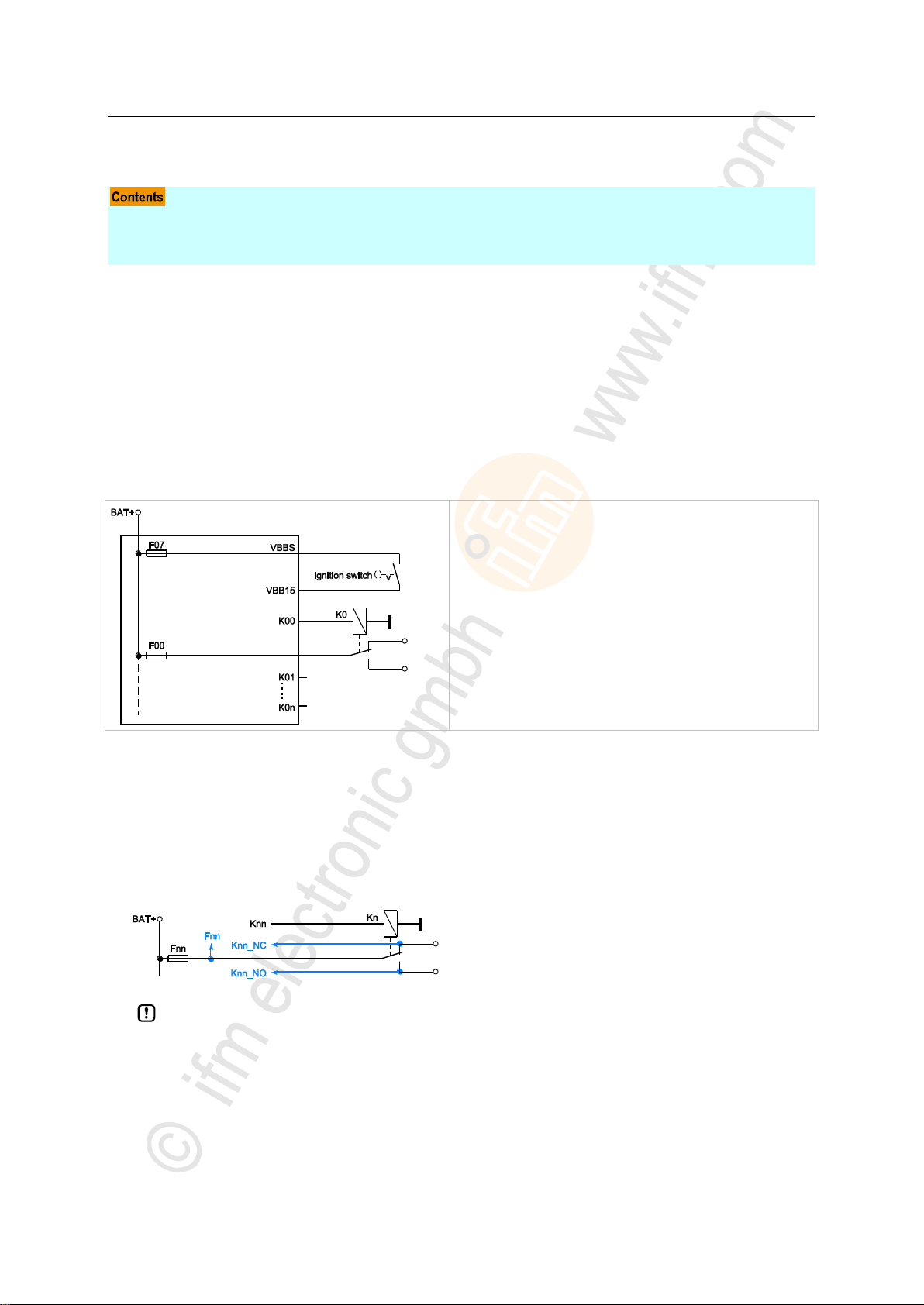
Start conditions
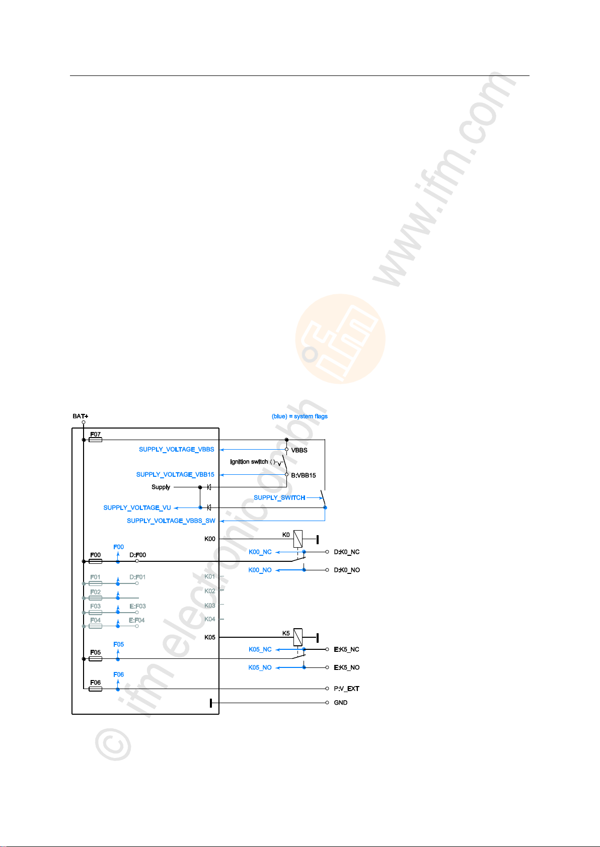
The device does not start before sufficient voltage is applied to the supply connection VBB15.
In vehicles VBB15 is the plus cable switched by the ignition lock.
A voltage > 8 V is deemed sufficient.
Permissible operating voltage → data sheet
Relays can only be switched on again if VBBs is applied and SUPLY_SWITCH is closed.
>
Important note to program the device
Applies to the following devices:
• BasicController relay CR0431
► For the time of programming interconnect the connections B:1 (VBB15) and B:8 (VBBs).
Otherwise programming is not possible.
Background:
The controller resets all outputs when programming begins, also SUPPLY_SWITCH.
Without VBB15 the controller would be separated from the voltage supply and is switched off.
When the controller is switched on again, the device is in bootloader mode.
The programmer has to load the Basic System to the device again.
Then reload the application program to the device.
>
19673
20763
Principle block diagram
19672
Figure: principle block diagram of supply and relays
12
Page 13

ifm Programming Manual BasicController relay CR0431 v03.03.00 05 / 2018
System description Hardware description
>
FLASH memory (non-volatile, slow memory)
overall existing in the device
1 536 kByte
maximum size of the application program
128 kByte
data other than the application program
read data with FB FLASH_READ (→ p. 184)
(files: 128 bytes less for header)
64 kByte
SRAM (volatile, fast memory)
overall existing in the device
SRAM indicates here all kinds of volatile and fast memories.
208 kByte
data reserved by the application program
32 kByte
FRAM (non-volatile, fast memory)
overall existing in the device
FRAM indicates here all kinds of non-volatile and fast memories.
2 kByte
variables in the application program, declared as VAR_RETAIN
128 Byte
fixed as remanent defined flags (%MB0...127)
128 Byte
Available memory
>
FLASH memory
Thereof the following memory areas are reserved for ...
The remaining rest of the memory is reserved for system internal purposes.
>
SRAM
13736
13053
12269
Thereof the following memory areas are reserved for ...
The remaining rest of the memory is reserved for system internal purposes.
>
FRAM
Thereof the following memory areas are reserved for ...
The remaining rest of the memory is reserved for system internal purposes.
2262
13
Page 14
ifm Programming Manual BasicController relay CR0431 v03.03.00 05 / 2018
System description Hardware description
>
Analogue inputs ......................................................................................................................................14
Binary inputs ...........................................................................................................................................15
Input group IN0...IN3 ..............................................................................................................................16
Input group IN4...IN7 ..............................................................................................................................16
In case of ratiometric measurement the connected sensors should be supplied with VBBs of the
device. So, faulty measurements caused by offset voltage are avoided.
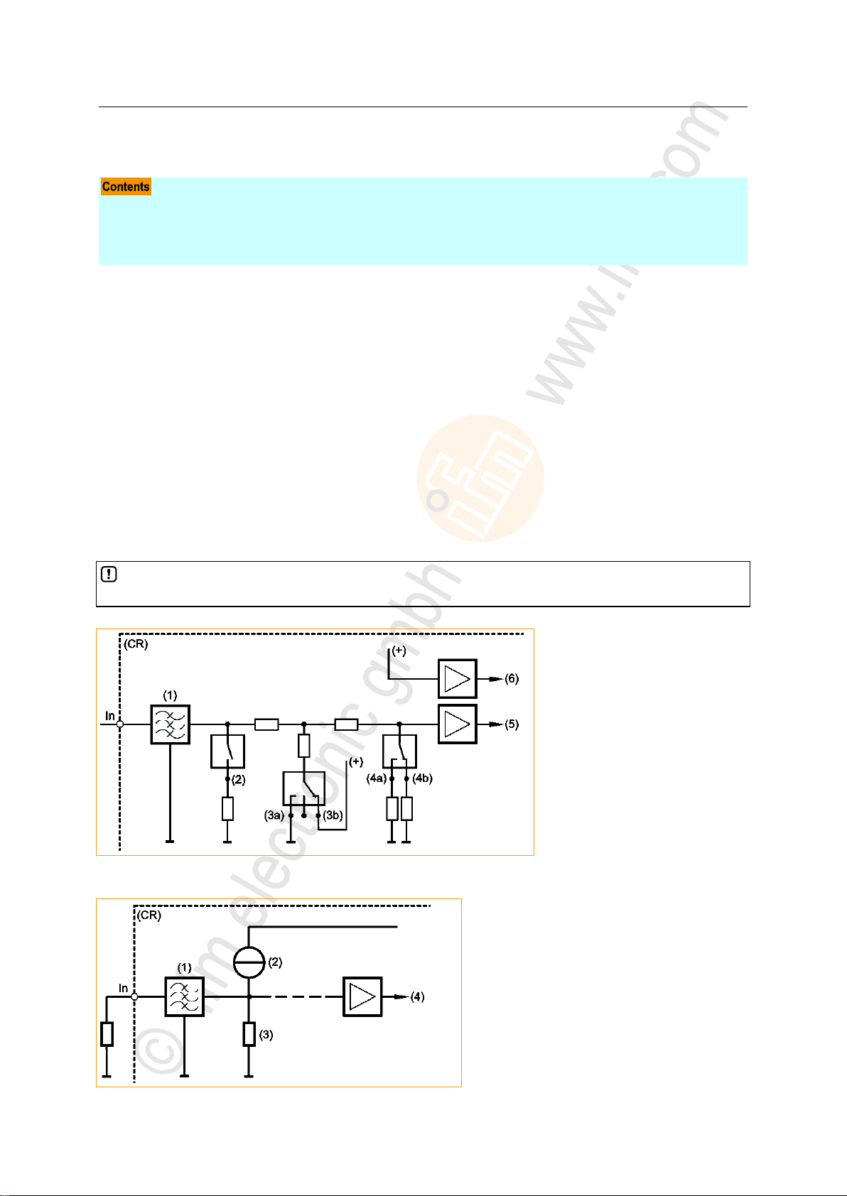
In = pin multifunction input n
(CR) = device
(1) = input filter
(2) = analogue current measuring
(3a) = binary-input plus switching
(3b) = binary-input minus switching
(4a) = analogue voltage measuring 0...10 V
(4b) = analogue voltage measuring 0...32 V
(5) = voltage
(6) = reference voltage
Figure: principle block diagram multifunction input
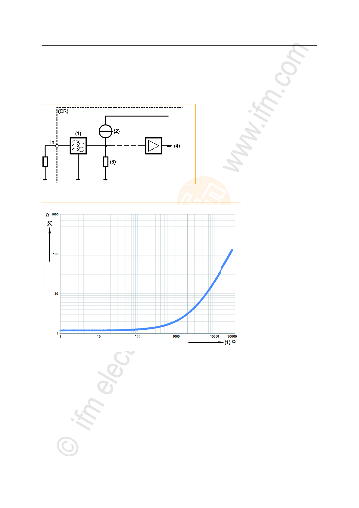
Figure: block diagram of the resistor survey input
In = pin resistor survey input n
(CR) = device
(1) = input filter
(2) = constant-current source
(3) = internal resistance
(4) = voltage
3.2.2 Inputs (technology)
>
14090
Analogue inputs
15444
The analogue inputs can be configured via the application program. The measuring range can be set
as follows:
• current input 0...20 mA
• voltage input 0...10 V
• voltage input 0...32 V
• resistance measurement 16...30 000 (measurement to GND)
The voltage measurement can also be carried out ratiometrically (0...1000 ‰, adjustable via function
blocks). This means potentiometers or joysticks can be evaluated without additional reference voltage.
A fluctuation of the supply voltage has no influence on this measured value.
As an alternative, an analogue channel can also be evaluated binarily.
8971
14
8972
Page 15
ifm Programming Manual BasicController relay CR0431 v03.03.00 05 / 2018
System description Hardware description
>
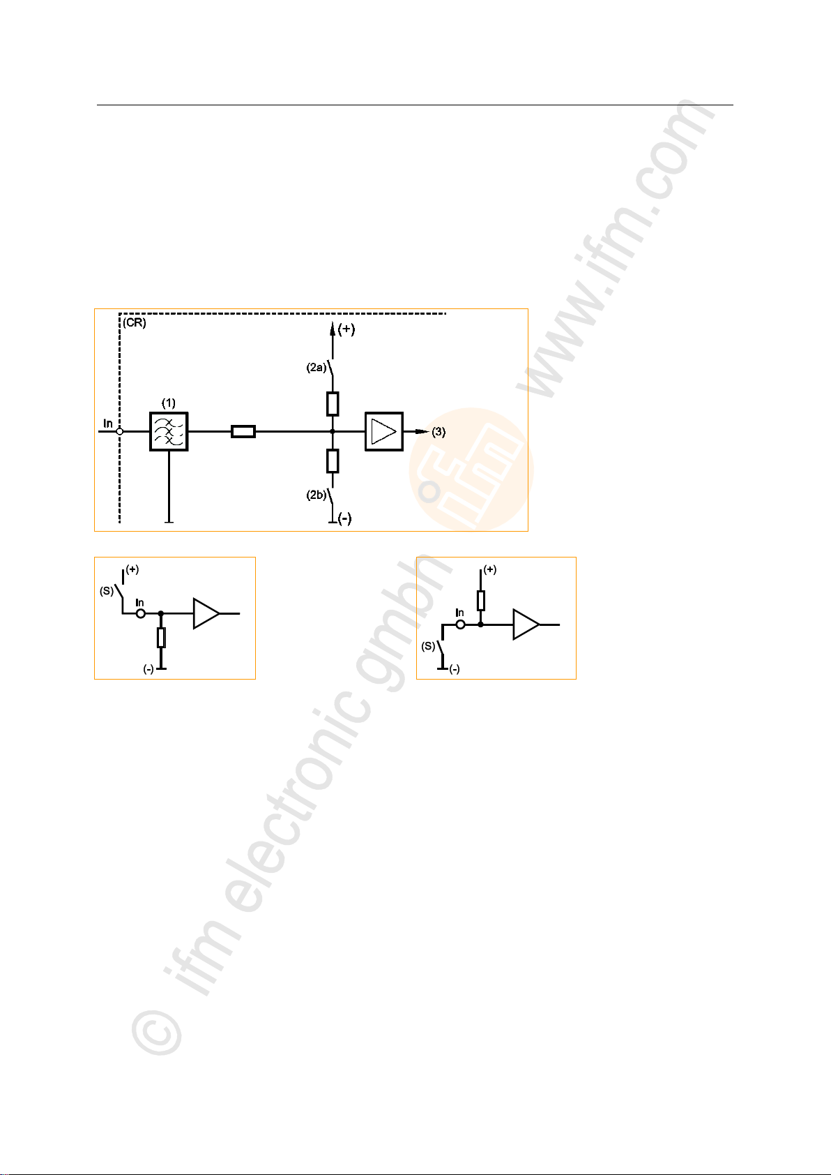
In = pin binary-input n
(CR) = device
(1) = input filter
(2a) = input minus switching
(2b) = input plus switching
(3) = voltage
Figure: basic circuit of binary input minus switching / plus switching for negative and positive sensor signals
In = pin binary input n
(S) = sensor
In = pin binary input n
(S) = sensor
Basic circuit of binary input plus switching (BL)
for positive sensor signal:
Input = open signal = low (GND)
Basic circuit of binary input minus switching (BH)
for negative sensor signal:
Input = open signal = high (supply)
Binary inputs
The binary input can be operated in following modes:
• binary input plus switching (BL) for positive sensor signal
• binary input minus switching (BH) for negative sensor signal
Depending on the device the binary inputs can configured differently. In addition to the protective
mechanisms against interference, the binary inputs are internally evaluated via an analogue stage.
This enables diagnosis of the input signals. But in the application software the switching signal is
directly available as bit information
1015
7345
For some of these inputs (→ data sheet) the potential can be selected to which it will be switched.
15
Page 16

ifm Programming Manual BasicController relay CR0431 v03.03.00 05 / 2018
System description Hardware description
>
Input group IN0...IN3
These inputs are a group of multifunction channels.
These inputs can be used as follows (each input separately configurable):
• analogue input 0...20 mA
• analogue input 0...10 V
• analogue input 0...32 V
• voltage measurement ratiometric 0...1000 ‰
• binary input plus switching (BL) for positive sensor signal (with/without diagnosis)
• binary input minus switching (BH) for negative sensor signal
• fast input for e.g. incremental encoders and frequency or interval measurement
→ chapter Possible operating modes inputs/outputs (→ p. 206)
Sensors with diagnostic capabilities to NAMUR can be evaluated.
All inputs show the same behaviour concerning function and diagnosis.
Detailed description → chapter Address assignment inputs / outputs (→ p. 204)
Configuration of each input is made via the application program:
• FB INPUT (→ p. 169) > input MODE
• FBs FASTCOUNT (→ p. 165), INC_ENCODER (→ p. 167) or PERIOD (→ p. 171)
> If the analogue inputs are configured for current measurement, the device switches to the safe
voltage measurement range (0...32 V DC) and the output RESULT is set accordingly in the
function block INPUT when the final value (23 mA for > 40 ms) is exceeded. After about one
second the input automatically switches back to the current measuring range.
>
14568
Input group IN4...IN7
These inputs are a group of multifunction channels.
These inputs can be used as follows (each input separately configurable):
• binary input plus switching (BL) for positive sensor signal
• input for resistance measurement (e.g. temperature sensors or fuel sensors)
→ chapter Possible operating modes inputs/outputs (→ p. 206)
Sensors with diagnostic capabilities to NAMUR can be evaluated.
► Configuration of each input is made via the application program:
• FB INPUT (→ p. 169) > input MODE
14569
16
Page 17
ifm Programming Manual BasicController relay CR0431 v03.03.00 05 / 2018
System description Hardware description
>
Figure: block diagram of the resistor survey input
In = pin resistor survey input n
(CR) = device
(1) = input filter
(2) = constant-current source
(3) = internal resistance
(4) = voltage
Figure: resolution dependent on the
resistance value
(1) = resistance value at the input
(2) = resolution
Resistance measurement
Typical sensors on these inputs:
• tank level
• temperature (PT1000, NTC)
9773
8972
The resistance for this device is not linearly dependent on the resistance value, → figure:
By how many ohms does the measured value change when the signal of the A/D converter on the input changes by 1?
Examples:
• In the range of 1...100 the resolution is 1.2 .
• In the range of 1 k the resolution is approx. 2 .
• In the range of 2 k the resolution is approx. 3 .
• In the range of 3 k the resolution is approx. 6 .
• In the range of 6 k the resolution is approx. 10 .
• In the range of 10 k the resolution is approx. 11
• In the range of 20 k the resolution is approx. 60 .
17
8970
Page 18
ifm Programming Manual BasicController relay CR0431 v03.03.00 05 / 2018
System description Hardware description
3.2.3 Outputs (technology)
Protective functions of the outputs .........................................................................................................18
Output group K0...K5 ..............................................................................................................................18
Output group LED0...LED6.....................................................................................................................19
► Adapt the value of the fuses...
• to the load capacity of the relays used.
• to the load capacity of the wiring.
>
Protective functions of the outputs
The outputs of this device are protected against overload and short circuit within specific ranges.
→ data sheet
>
Fuses, relays
The relay outputs are protected via fuses:
14093
15248
19676
>
Output group K0...K5
These outputs are a group of channels with a single specified function.
These outputs have the following fixed setting:
• binary output with relay (change-over contacts)
• The outputs have no current measurement, no overload detection.
• The device measures the voltages on all relay contacts.
The measured values are also available in system flags:
x = 0...n (depending on the device)
► For the limit values please make sure to adhere to the data sheet!
19678
18
Page 19

ifm Programming Manual BasicController relay CR0431 v03.03.00 05 / 2018
System description Hardware description
>
Output group LED0...LED6
These outputs are a group of channels with a single specified function.
These outputs have the following fixed setting:
• binary output with LED (e.g. diagnostic message)
The LED outputs can be freely used in the application.
The spatial arrangement on the device provides the following assignment:
• LED0 indicates intact fuse F0
• LED1 indicates intact fuse F1
etc.
19682
19
Page 20

ifm Programming Manual BasicController relay CR0431 v03.03.00 05 / 2018
System description Hardware description
3.2.4 Note on wiring
A
Analogue input
BH
Binary high side input: minus switching for negative sensor signal
Binary high side output: plus switching for positive output signal
BL
Binary low side input: plus switching for positive sensor signal
Binary low side output: minus switching for negative output signal
CYL
Input period measurement
ENC
Input encoder signals
FRQ
Frequency input
H bridge
Output with H-bridge function
PWM
Pulse-width modulated signal
PWMi
PWM output with current measurement
IH
Pulse/counter input, high side: minus switching for negative sensor signal
IL
Pulse/counter input, low side: plus switching for positive sensor signal
R
Read back channel for one output
Contacts of Reed relays may be clogged (reversibly) if connected to the device inputs without
series resistor.
1426
The wiring diagrams (→ installation instructions of the devices, chapter "Wiring") describe the standard
device configurations. The wiring diagram helps allocate the input and output channels to the IEC
addresses and the device terminals.
The individual abbreviations have the following meaning:
Allocation of the input/output channels: → Catalogue, mounting instructions or data sheet
>
3.2.5 Safety instructions about Reed relays
For use of non-electronic switches please note the following:
► Remedy: Install a series resistor for the Reed relay:
Series resistor = max. input voltage / permissible current in the Reed relay
Example: 32 V / 500 mA = 64 Ohm
► The series resistor must not exceed 5 % of the input resistance RE of the device input→ data
sheet). Otherwise, the signal will not be detected as TRUE.
Example:
RE = 3 000 Ohm
max. series resistor = 150 Ohm
7348
6915
20
Page 21
ifm Programming Manual BasicController relay CR0431 v03.03.00 05 / 2018
System description Hardware description
>
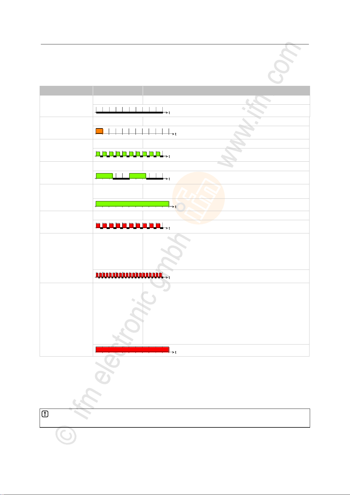
LED colour
Display
Description
Off
Permanently off
No operating voltage
Orange
Briefly on
Initialisation or reset checks
(time frame = 200 ms)
Green
Flashing with 5 Hz
no runtime system loaded
(time frame = 200 ms)
Green
Flashing with 2 Hz
Application = RUN
(time frame = 200 ms)
Green
Permanently on
Application = STOP
or: no application loaded
Red
Flashing with 5 Hz
Application = stopped because of undervoltage
(time frame = 200 ms)
Red
Flashing with 10 Hz
Application = STOP with error
application program is stopped
Cause: exceeded timeout of the application or visualisation:
Delete the application!
PowerOn reset
Reload the application into the device
(time frame = 200 ms)
Red
Permanently on
Application = STOP and FATAL ERROR
Cause: software watchdog has failed
PowerOn reset
If without success:
Goto Bootloader
PowerOn reset
Reload the BasicSystem into the device
Reload the application into the device
If without success:
Hardware error: send device to ifm!
The use of the LED function block in the application program replaces the system setting of the
status LED in the RUN state.
3.2.6 Status-LED
The operating states are indicated by the integrated status LED (default setting).
7998
The status LED can be changed by the programming system for the operating states STOP and RUN.
>
Control the LED in the application program
Via SET_LED frequency and color of the status LED can be changed in the application program.
21
15481
Page 22

ifm Programming Manual BasicController relay CR0431 v03.03.00 05 / 2018
System description Interface description
>
CAN interfaces .......................................................................................................................................22
CAN: interfaces and protocols ................................................................................................................22
CAN interface
CAN 1
CAN 2
CAN 3
CAN 4
Default download ID
ID 127
ID 126
ID 125
ID 124
CAN protocols
CAN Layer 2
CAN Layer 2
Interface does not
exist
Interface does not
exist
CANopen
CANopen
SAE J1939
SAE J1939
3.3 Interface description
14098
3.3.1 CAN interfaces
14101
Connections and data → data sheet
>
CAN: interfaces and protocols
14589
15238
The devices are equipped with several CAN interfaces depending on the hardware design. Basically,
all interfaces can be used with the following functions independently of each other:
• RAW-CAN (Layer 2): CAN on level 2 (→ chapter Function elements: RAW-CAN (Layer 2) (→ p. 60))
• CANopen master / CANopen slave (→ chapter Function elements: CANopen (→ p. 86))
• CANopen network variables (via CODESYS) (→ chapter Network variables (→ p. 52))
• SAE J1939 (for drive management, → chapter Function elements: SAE J1939 (→ p. 132))
• Bus load detection
• Error frame counter
• Download interface
• 100 % bus load without package loss
The following CAN interfaces and CAN protocols are available in this ecomatmobile device:
14591
Standard baud rate = 250 Kbits/s
All CAN interfaces can operate with all CAN protocols at the same time. The IDs used must not
impair each other!
22
Page 23

ifm Programming Manual BasicController relay CR0431 v03.03.00 05 / 2018
System description Software description
3.4 Software description
Software modules for the device ............................................................................................................23
Programming notes for CODESYS projects ...........................................................................................26
Operating states .....................................................................................................................................29
Performance limits of the device ............................................................................................................31
Bootloader ..............................................................................................................................................24
Runtime system ......................................................................................................................................24
Application program ................................................................................................................................24
Libraries ..................................................................................................................................................25
software module
Can user change the module?
By means of what tool?
Application program
with libraries
yes
CODESYS,
MaintenanceTool
Runtime system *)
Upgrade yes
Downgrade yes
MaintenanceTool
Bootloader
no
---
(Hardware)
no
---
3.4.1 Software modules for the device
The software in this device communicates with the hardware as below:
14107
14110
*) The runtime system version number must correspond to the target version number in the CODESYS target system setting.
→ chapter Set up the target (→ p. 38)
Below we describe this software module:
23
Page 24

ifm Programming Manual BasicController relay CR0431 v03.03.00 05 / 2018
System description Software description
>
WARNING
The user is responsible for the reliable function of the application programs he designed. If necessary,
he must additionally carry out an approval test by corresponding supervisory and test organisations
according to the national regulations.
Bootloader
14111
On delivery ecomatmobile controllers only contain the boot loader.
The boot loader is a start program that allows to reload the runtime system and the application
program on the device.
The boot loader contains basic routines...
• for communication between hardware modules,
• for reloading the operating system.
The boot loader is the first software module to be saved on the device.
>
Runtime system
14112
Basic program in the device, establishes the connection between the hardware of the device and the
application program.
→ chapter Software modules for the device (→ p. 23)
On delivery, there is normally no runtime system loaded in the controller (LED flashes green at 5 Hz).
Only the bootloader is active in this operating mode. It provides the minimum functions for loading the
runtime system, among others support of the interfaces (e.g. CAN).
Normally it is necessary to download the runtime system only once. Then, the application program can
be loaded into the controller (also repeatedly) without affecting the runtime system.
The runtime system is provided with this documentation on a separate data carrier. In addition, the
current version can be downloaded from the website of ifm electronic gmbh:
→ www.ifm.com
>
Application program
14118
Software specific to the application, implemented by the machine manufacturer, generally containing
logic sequences, limits and expressions that control the appropriate inputs, outputs, calculations and
decisions.
8340
24
Page 25

ifm Programming Manual BasicController relay CR0431 v03.03.00 05 / 2018
System description Software description
>
Library
Use
ifm_CR0431_Vxxyyzz.LIB
Device-specific library
Must always be contained in the application program!
ifm_RawCAN_NT_Vxxyyzz.LIB
(optional)
when a CAN interface of the device is to be operated with CAN
Layer 2
ifm_CANopen_NT_Vxxyyzz.LIB
(optional)
when a CAN interface of the device is to be operated as
CANopen master or CANopen slave
ifm_J1939_NT_Vxxyyzz.LIB
(optional)
when a CAN interface of the device is to communicate with a
motor control
Libraries
15409
ifm electronic offers several libraries (*.LIB) to match each device containing program modules for
the application program. Examples:
Details: → chapter ifm libraries for the device CR0431 (→ p. 53)
25
Page 26

ifm Programming Manual BasicController relay CR0431 v03.03.00 05 / 2018
System description Software description
3.4.2 Programming notes for CODESYS projects
FB, FUN, PRG in CODESYS .................................................................................................................26
Note the cycle time! ................................................................................................................................27
Important note to program the device ....................................................................................................27
Creating application program .................................................................................................................28
Using ifm maintenance tool ....................................................................................................................29
Distribution of the application program ...................................................................................................29
NOTE
Function blocks must NOT be called in functions!
Otherwise: During execution the application program will crash.
All function elements must NOT be called recursively, nor indirectly!
An IEC application may contain maximum 8000 function elements; in this device maximum 512
function elements!
Here you receive tips how to program the device.
► See the notes in the CODESYS programming manual.
>
FB, FUN, PRG in CODESYS
In CODESYS we differentiate between the following types of function elements:
FB = function block
• An FB can have several inputs and several outputs.
• An FB may be called several times in a project.
• An instance must be declared for each call.
• Permitted: Call FB and FUN in FB.
FUN = function
• A function can have several inputs but only one output.
• The output is of the same data type as the function itself.
PRG = program
• A PRG can have several inputs and several outputs.
• A PRG may only be called once in a project.
• Permitted: Call PRG, FB and FUN in PRG.
7426
15410
Background:
All variables of functions...
• are initialised when called and
• become invalid after return to the caller.
Function blocks have 2 calls:
• an initialisation call and
• the actual call to do something.
Consequently that means for the function block call in a function:
• every time there is an additional initialisation call and
• the data of the last call gets lost.
26
Page 27

ifm Programming Manual BasicController relay CR0431 v03.03.00 05 / 2018
System description Software description
>
NOTICE
Risk that the device acts too slowly!
Cycle time must not become too long!
► When designing the application program the above-mentioned recommendations must be
complied with and tested.
► If necessary, the cycle time must be optimised by restructuring the software and the system
set-up.
Note the cycle time!
For the programmable devices from the controller family ecomatmobile numerous functions are
available which enable use of the devices in a wide range of applications.
As these units use more or fewer system resources depending on their complexity it is not always
possible to use all units at the same time and several times.
>
Important note to program the device
Applies to the following devices:
• BasicController relay CR0431
► For the time of programming interconnect the connections B:1 (VBB15) and B:8 (VBBs).
Otherwise programming is not possible.
Background:
The controller resets all outputs when programming begins, also SUPPLY_SWITCH.
Without VBB15 the controller would be separated from the voltage supply and is switched off.
When the controller is switched on again, the device is in bootloader mode.
The programmer has to load the Basic System to the device again.
Then reload the application program to the device.
8006
20763
27
Page 28
ifm Programming Manual BasicController relay CR0431 v03.03.00 05 / 2018
System description Software description
>
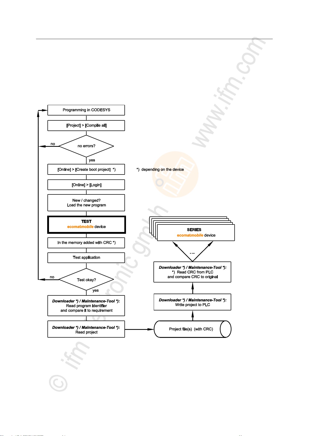
Creating application program
The application program is generated by the CODESYS 2.3 programming system and loaded in the
controller several times during the program development for testing:
In CODESYS: [Online] > [Login] > load the new program.
For each such download via CODESYS 2.3 the source code is translated again. The result is that
each time a new checksum is formed in the controller memory. This process is also permissible for
safety controllers until the release of the software.
8007
Graphics: Creation and distribution of the software
28
Page 29

ifm Programming Manual BasicController relay CR0431 v03.03.00 05 / 2018
System description Software description
>
Using ifm maintenance tool
8492
The ifm Maintenance Tool serves for easy transfer of the program code from the programming station
to the controller. As a matter of principle each application software can be copied to the controllers
using the ifm Maintenance Tool. Advantage: A programming system with CODESYS licence is not
required.
Here you will find the current ifm Maintenance Tool:
Homepage → www.ifm.com
>
Distribution of the application program
8493
We recommend the following sequence, if the application software is to be copied to the series
machine and used:
Saving the software
After completion of program development the latest version of the application program loaded in
the controller using the ifm Maintenance Tool has to be read from the controller and saved on a
data carrier using the name project_file.RESX. Only this process ensures that the application
software and its checksums are stored.
Download of the software.
To equip all machines of a series production with an identical software only this file may be loaded
in the controllers using the ifm Maintenance Tool.
An error in the data of this file is automatically recognised by the integrated checksum when
loaded again using the ifm Maintenance Tool.
>
3.4.3 Operating states
After power on the ecomatmobile device can be in one of five possible operating states:
• BOOTLOADER
• INIT
• STOP
• RUN
• SYSTEM STOP
>
INIT state (Reset)
Premise: a valid runtime system is installed.
This state is passed through after every power on reset:
> The runtime system is initialised.
> Various checks are carried out, e.g. waiting for correctly power supply voltage.
> This temporary state is replaced by the RUN or STOP state.
> The LED lights orange.
Change out of this state possible into one of the following states:
• RUN
• STOP
1075
20647
29
Page 30

ifm Programming Manual BasicController relay CR0431 v03.03.00 05 / 2018
System description Software description
>
STOP state
A transition into this state is possible in the following cases:
• from the INIT state if no application program is loaded.
• From the RUN state if the following condition is met:
• The STOP command is sent via the CODESYS interface.
In the STOP state:
> The outputs of the device are switched off.
> Processing of the application program is stopped.
> The LED lights green.
A transition from this state into one of the following states is possible:
• RUN
• ERROR
• FATAL ERROR
• INIT (after power-on-reset)
>
RUN state
A transition into this state is possible in the following cases:
from the INIT state (autostart) if the following conditions are met:
• The operating voltage has reached a minimum value. AND:
• The application program exists.
From the STOP state:
• via the CODESYS command RUN.
• The operating voltage has reached or exceeded a minimum value.
In the RUN state:
> The runtime system is running.
> The application program is running.
> The LED flashes green with 2 Hz.
The LED can be controlled differently by the application program → FB SET_LED (→ p. 196).
A transition from this state into one of the following states is possible:
• INIT (after power-on-reset)
• STOP
• ERROR
• FATAL ERROR
8288
8287
30
Page 31

ifm Programming Manual BasicController relay CR0431 v03.03.00 05 / 2018
System description Software description
>
Note the limits of the device! → Data sheet
ERROR state
A transition into this state is possible in the following cases:
• if the supply voltage is too low.
In the ERROR state:
> The outputs of the device are switched off.
> Processing of the application program is stopped.
> System parameters are saved.
> The LED flashed red with 5 Hz.
A transition from this state into one of the following states is possible:
• INIT (after power-on-reset)
• RUN
• STOP
• FATAL ERROR
>
FATAL ERROR state
A transition into this state is possible in the following cases:
• memory error (RAM / Flash)
• exception error
• runtime system error
In the FATAL ERROR state:
> The outputs of the device are switched off.
> The application program is terminated.
> The runtime system is terminated.
> The LED lights red.
A transition from this state into one of the following states is possible:
• INIT (after power-on-reset)
>
8290
8289
3.4.4 Performance limits of the device
7358
31
Page 32

ifm Programming Manual BasicController relay CR0431 v03.03.00 05 / 2018
System description Software description
>
Device
BasicController: CR040n, CR041n,
CR043n
BasicDisplay: CR045n
ioControl: CR205n
SmartController: CR253n
PDM360 NG: CR108n, CR120n
Criterion
max. FiFo transmit
- with FB CAN_TX...
- with FB CAN_TX_ENH...
4 messages
16 messages
4 messages
16 messages
max. FiFo receive
- with FB CAN_RX_..._FIFO
32 messages
32 messages
Watchdog behaviour
In this device, a watchdog monitors the program runtime of the CODESYS application.
If the maximum watchdog time (100 ms) is exceeded:
> the device changes to the "Timeout Error" state
> all processes are stopped (reset)
> all outputs are switched off
> the status LED flashes red at 10 Hz
Eliminate the fault:
Delete application program!
PowerOn reset
Reload the application program into the device
If the watchdog in question fails:
> a second watchdog leads the device to the state "Fatal Error"
> the status LED lights red
Eliminate the fault:
PowerOn reset
If without success:
Goto Bootloader
PowerOn reset
Reload the runtime system into the device
Reload the application program into the device
If without success:
Hardware error: send device to ifm!
>
15365
Limitations for CAN in this device
17975
FIFO (First In, First Out) = Operating principle of the stack memory: The data packet that was
written into the stack memory first, will also be read first. Each identifier has such a buffer (queue).
Some Raw-CAN function elements enable transmitting and receiving of several messages in one PLC
cycle as the messages are temporarily stored in a FiFo:
- CAN_TX..., → Function elements: transmit RAW-CAN data
- CAN_RX_ENH_FIFO (→ p. 70)
- CAN_RX_RANGE_FIFO (→ p. 74)
The number of FIFo messages is limited. The following limitations of the devices are valid:
32
Page 33

ifm Programming Manual BasicController relay CR0431 v03.03.00 05 / 2018
System description Software description
>
Device
BasicController: CR040n, CR041n,
CR043n
BasicDisplay: CR045n
ioControl: CR205n
SmartController: CR253n
PDM360 NG: CR108n, CR120n
Criterion
max. guarding error
32 messages
128 messages
max. SDO data
2 048 bytes
2 048 bytes
Device
BasicController: CR040n, CR041n,
CR043n
BasicDisplay: CR045n
ioControl: CR205n
SmartController: CR253n
PDM360 NG: CR108n, CR120n
Criterion
max. FiFo transmit
- with FB J1939_TX
- with FB J1939_TX_ENH
4 messages
16 messages
4 messages
16 messages
max. FiFo receive
- with FB J1939_RX_FIFO
32 messages
32 messages
max. DTCs
64 messages
64 messages
max. data J1939
1 785 bytes
1 785 bytes
Limitations for CANopen in this device
The following limitations of the devices are valid:
>
Limitations for CAN J1939 in this device
The following limitations of the devices are valid:
17976
17977
33
Page 34

ifm Programming Manual BasicController relay CR0431 v03.03.00 05 / 2018
Configurations Set up the runtime system
4 Configurations
Set up the runtime system ......................................................................................................................34
Set up the programming system ............................................................................................................37
Function configuration in general ...........................................................................................................41
Function configuration of the inputs and outputs ...................................................................................42
Variables .................................................................................................................................................50
Reinstall the runtime system ..................................................................................................................35
Update the runtime system.....................................................................................................................36
Verify the installation ..............................................................................................................................36
1016
The device configurations described in the corresponding installation instructions or in the Appendix
(→ p. 202) to this documentation are used for standard devices (stock items). They fulfil the requested
specifications of most applications.
Depending on the customer requirements for series use it is, however, also possible to use other
device configurations, e.g. with respect to the inputs/outputs and analogue channels.
4.1 Set up the runtime system
14091
34
Page 35

ifm Programming Manual BasicController relay CR0431 v03.03.00 05 / 2018
Configurations Set up the runtime system
>
NOTICE
Risk of data loss!
In case of power failure during the data transmission data can be lost so that the device is no longer
functionable. Repair is only possible by ifm electronic.
► Ensure an uninterrupted power supply during the data transmission!
NOTE
The software versions suitable for the selected target must always be used:
• runtime system (ifm_CR0431_Vxxyyzz.RESX),
• PLC configuration (ifm_CR0431_Vxx.CFG),
• device library (ifm_CR0431_Vxxyyzz.LIB ) and
• the further files.
V
xx: 00...99
yy: 00...99
zz: 00...99
version
target version number
release number
patch number
The basic file name (e.g. "CR0431") and the software version number "xx" (e.g. "01") must always have
the same value! Otherwise the device goes to the STOP mode.
The values for "yy" (release number) and "zz" (patch number) do not have to match.
4.1.1 Reinstall the runtime system
14635
8486
On delivery of the ecomatmobile controller no runtime system is normally loaded (LED flashes green
at 5 Hz). Only the boot loader is active in this operating mode. It provides the minimum functions for
loading the operating system (e.g. RS232, CAN).
Normally it is necessary to download the runtime system only once. The application program can then
be loaded to the device (also several times) without influencing the runtime system.
The runtime system is provided with this documentation on a separate data carrier. In addition, the
current version can be downloaded from the website of ifm electronic gmbh:
→ www.ifm.com
8651
8485
The following files must also be loaded:
• the internal libraries (created in IEC 1131) required for the project,
• the configuration files (*.CFG) and
• the target files (*.TRG).
It may happen that the target system cannot or only partly be programmed with your currently
installed version of CODESYS. In such a case, please contact the technical support department of ifm
electronic gmbh.
Contact → www.ifm.com
The runtime system is transferred to the device using the separate program "Maintenance Tool". (The
program can be downloaded from ifm's website, if necessary):
→ www.ifm.com
Normally the application program is loaded to the device via the programming system. But it can also
be loaded using the "Maintenance Tool" if it was first read from the device.
35
4368
Page 36

ifm Programming Manual BasicController relay CR0431 v03.03.00 05 / 2018
Configurations Set up the runtime system
>
NOTICE
Risk of data loss!
When deleting or updating the runtime system all data and programs on the device are deleted.
► Save all required data and programs before deleting or updating the runtime system!
GET_SW_INFO (→ p. 188)
Delivers information about the system software of the device:
• software name,
• software version,
• build number,
• build date
4.1.2 Update the runtime system
13269
An older runtime system is already installed on the device. Now, you would like to update the runtime
system on the device?
14158
For this operation, the same instructions apply as in the previous chapter 'Reinstall the runtime
system'.
>
4.1.3 Verify the installation
14637
► After loading of the runtime system into the controller:
• Check whether the runtime system was transmitted correctly!
• Check whether the correct runtime system is loaded in the controller!
► 1st test:
Test with the ifm maintenance tool if the correct runtime system version was loaded:
• Read name and version of the runtime system in the device!
• Manually compare this information with the target data!
► 2nd test (optional):
Check in the application program if the correct runtime system version was loaded:
• read name and version of the runtime system in the device!
• Compare this data with the specified values!
The following FB serves for reading the data:
► If the application detects an incorrect version of a runtime system:
bring all safety functions into the safe state.
36
Page 37

ifm Programming Manual BasicController relay CR0431 v03.03.00 05 / 2018
Configurations Set up the programming system
>
Set up the programming system manually .............................................................................................37
Set up the programming system via templates ......................................................................................41
Set up the target .....................................................................................................................................38
Activate the PLC configuration ...............................................................................................................39
CAN declaration (e.g. CR1080) ..............................................................................................................40
4.2 Set up the programming system
4.2.1 Set up the programming system manually
14461
3963
37
Page 38

ifm Programming Manual BasicController relay CR0431 v03.03.00 05 / 2018
Configurations Set up the programming system
>
NOTE
The software versions suitable for the selected target must always be used:
• runtime system (ifm_CR0431_Vxxyyzz.RESX),
• PLC configuration (ifm_CR0431_Vxx.CFG),
• device library (ifm_CR0431_Vxxyyzz.LIB ) and
• the further files.
V
xx: 00...99
yy: 00...99
zz: 00...99
version
target version number
release number
patch number
The basic file name (e.g. "CR0431") and the software version number "xx" (e.g. "01") must always have
the same value! Otherwise the device goes to the STOP mode.
The values for "yy" (release number) and "zz" (patch number) do not have to match.
Set up the target
13136
11379
When creating a new project in CODESYS the target file corresponding to the device must be loaded.
► Select the requested target file in the dialogue window [Target Settings] in the menu
[Configuration].
> The target file constitutes the interface to the hardware for the programming system.
> At the same time, several important libraries and the PLC configuration are loaded when selecting
the target.
► If necessary, in the window [Target settings] > tab [Network functionality] > activate [Support
parameter manager] and / or activate [Support network variables].
► If necessary, remove the loaded (3S) libraries or complement them by further (ifm) libraries.
► Always complement the appropriate device library ifm_CR0431_Vxxyyzz.LIB manually!
8485
The following files must also be loaded:
• the internal libraries (created in IEC 1131) required for the project,
• the configuration files (*.CFG) and
• the target files (*.TRG).
It may happen that the target system cannot or only partly be programmed with your currently
installed version of CODESYS. In such a case, please contact the technical support department of ifm
electronic gmbh.
Contact → www.ifm.com
4368
38
Page 39
ifm Programming Manual BasicController relay CR0431 v03.03.00 05 / 2018
Configurations Set up the programming system
>
Activate the PLC configuration
10079
The PLC configuration is automatically loaded with the target system. The PLC configuration maps the
contents of the file CR0431.cfg in CODESYS. Like this, the programmer has easy access to
predefined system and error flags, inputs and outputs as well as to the CAN interfaces of the device.
To access the PLC configuration (e.g. CR1080):
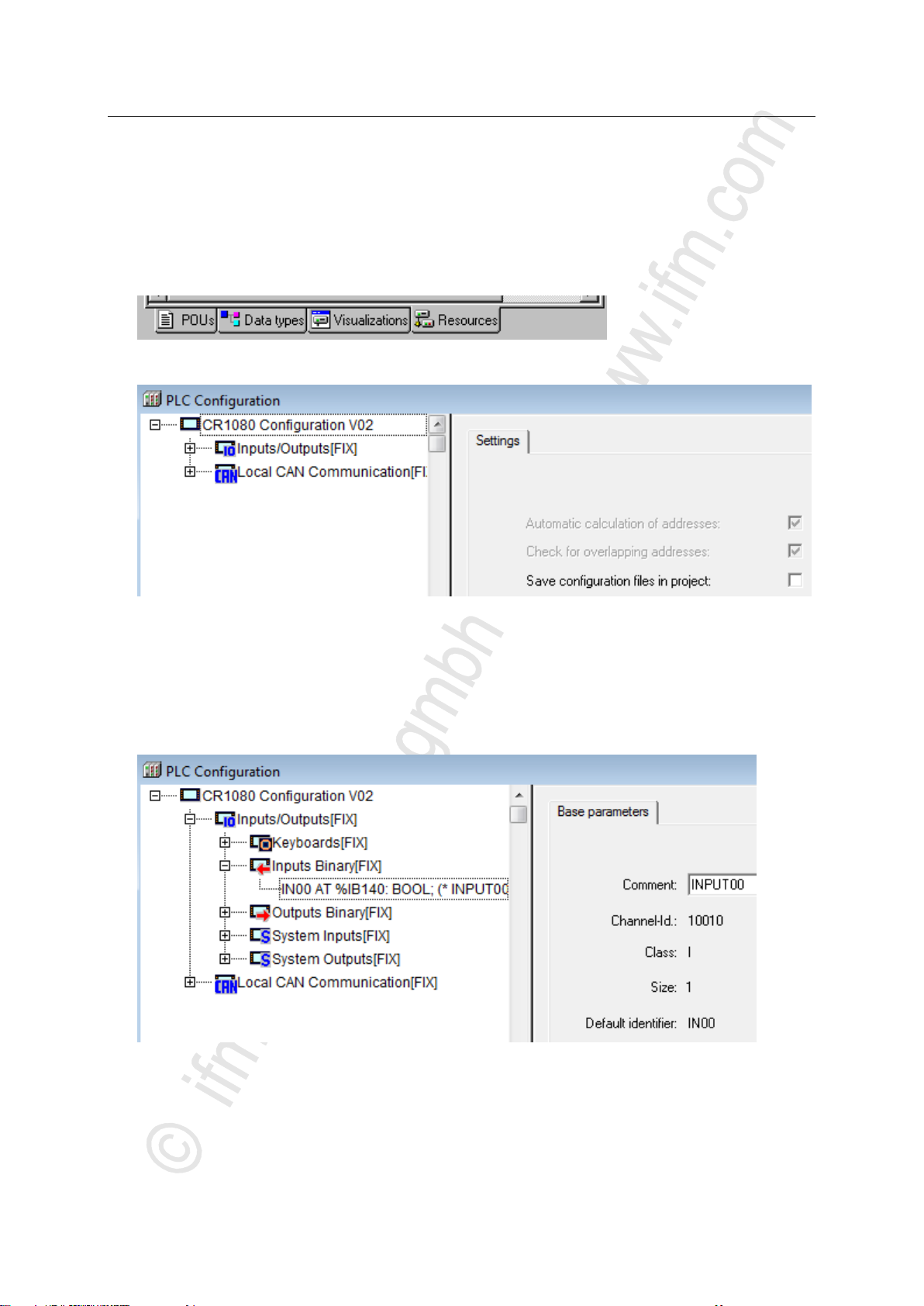
► Click on the tab [Resources] in CoDeSys:
► Double-click on [PLC Configuration] in the left column.
> Display of the current PLC configuration ( following figure):
> Based on the configuration the following is available in the program environment for the user:
System and error flags
Depending on the application and the application program, these flags must be processed and
evaluated. Access is made via their symbolic names.
Structure of the inputs and outputs
These can be directly symbolically designated (highly recommended!) in the window [PLC
Configuration] (example → figure below) and are available in the whole project as [Global
Variables].
39
Page 40
ifm Programming Manual BasicController relay CR0431 v03.03.00 05 / 2018
Configurations Set up the programming system
>
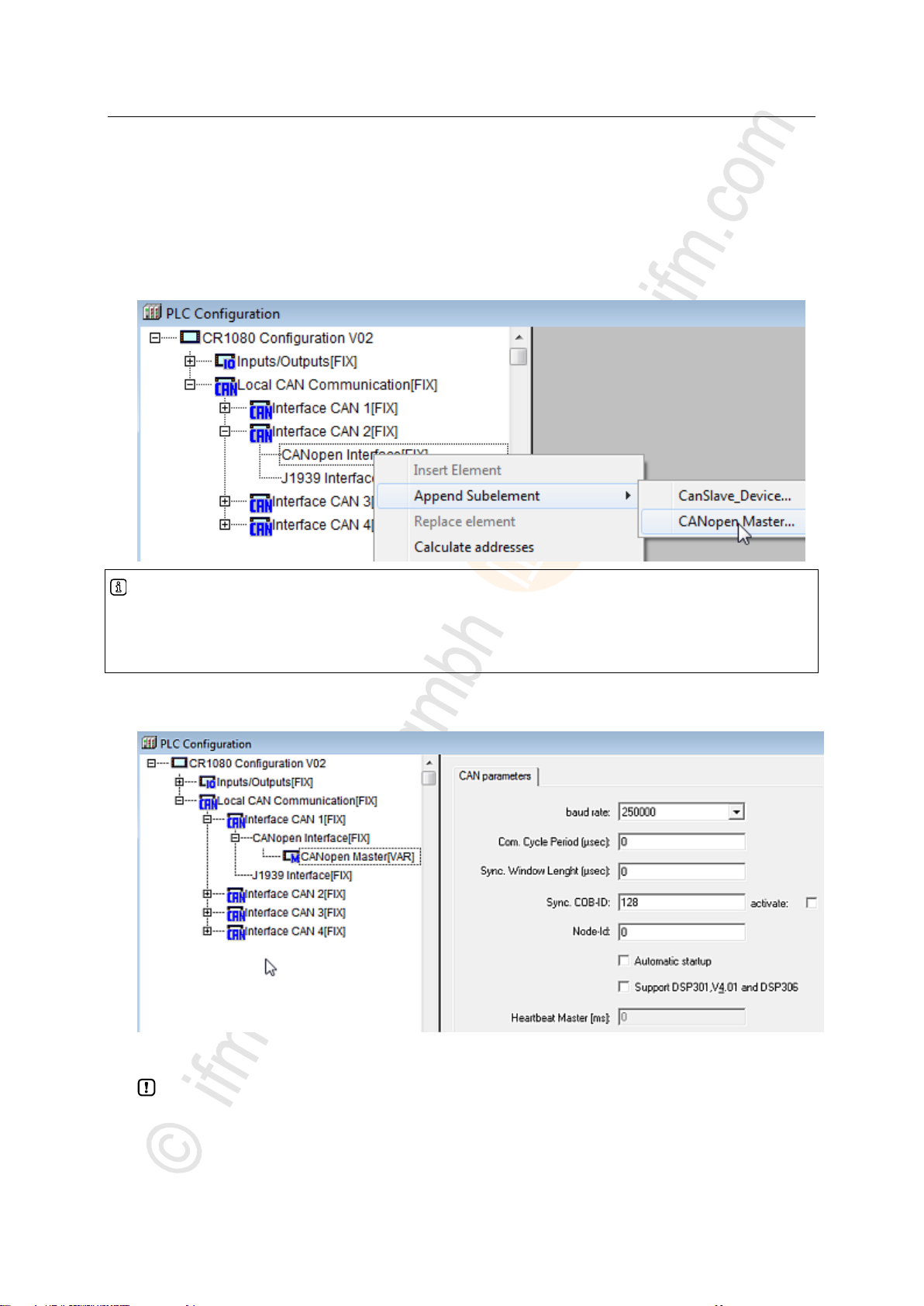
Info
If the device is operated as a slave, the selection [CanSlave_Device] would also be possible.
For the simpler configuration as a master, all CAN Layer 2 and network variable functions can also be
used.
CAN declaration (e.g. CR1080)
In the CODESYS PLC configuration you now have to declare the CAN interface(s).
► Right-click on the name of the PLC configuration. [CANopen Interface [FIX]] of the desired CAN
interface.
► Click on [Append Subelement].
► Even if the device is operated as a CANopen slave: Click on [CANopen Master...]:
10080
> The CAN parameters of the PLC configuration are displayed. Some CAN parameters are already
set as default:
► If the device is operated on CAN Layer 2 or as a slave via network variables or CAN_RX /
CAN_TX:
Check whether the correct baud rate is set for the device (baud rate must be identical for all
participants).
► If the device is operated as a CANopen master:
Check all parameter settings.
► Close the window [PLC Configuration].
40
Page 41

ifm Programming Manual BasicController relay CR0431 v03.03.00 05 / 2018
Configurations Function configuration in general
► In the menu [File] > [Save as ...] give a sensible name to the project and save it in the requested
When installing the ecomatmobile DVD "Software, tools and documentation", projects with
templates have been stored in the program directory of your PC:
…\ifm electronic\CoDeSys V…\Projects\Template_DVD_V…
► Open the requested template in CODESYS via:
[File] > [New from template…]
> CODESYS creates a new project which shows the basic program structure. It is strongly
recommended to follow the shown procedure.
directory.
► In the application program always call an own instance of the FB CANOPEN_ENABLE (→ p. 87)
for every CAN interface!
>
4.2.2 Set up the programming system via templates
13745
ifm offers ready-to-use templates (program templates), by means of which the programming system
can be set up quickly, easily and completely.
>
4.3 Function configuration in general
>
970
3971
4.3.1 System variables
All system variables (→ chapter System flags (→ p. 202)) have defined addresses which cannot be
shifted.
15576
41
Page 42

ifm Programming Manual BasicController relay CR0431 v03.03.00 05 / 2018
Configurations Function configuration of the inputs and outputs
>
Configuration of the inputs (default setting) ............................................................................................42
Configure inputs .....................................................................................................................................43
Configure outputs ...................................................................................................................................48
4.4 Function configuration of the inputs and outputs
7995
1394
For some devices of the ecomatmobile controller family, additional diagnostic functions can be
activated for the inputs and outputs. So, the corresponding input and output signal can be monitored
and the application program can react in case of a fault.
Depending on the input and output, certain marginal conditions must be taken into account when
using the diagnosis:
► It must be checked by means of the data sheet if the device used has the described input and
output groups (→ data sheet).
Constants are predefined (e.g. IN_DIGITAL_H) in the device libraries (ifm_CR0431_Vxxyyzz.LIB
) for the configuration of the inputs and outputs.
For details → Possible operating modes inputs/outputs (→ p. 206).
>
4.4.1 Configuration of the inputs (default setting)
19686
All inputs are in the binary mode (positive switching!) when delivered.
The diagnostic function is not active.
42
Page 43

ifm Programming Manual BasicController relay CR0431 v03.03.00 05 / 2018
Configurations Function configuration of the inputs and outputs
>
Safety instructions about Reed relays ....................................................................................................43
Analogue inputs: configuration and diagnosis ........................................................................................44
Binäry inputs: configuration and diagnosis .............................................................................................46
Fast inputs ..............................................................................................................................................47
Contacts of Reed relays may be clogged (reversibly) if connected to the device inputs without
series resistor.
4.4.2 Configure inputs
Valid operating modes → chapter Possible operating modes inputs/outputs (→ p. 206)
>
Safety instructions about Reed relays
For use of non-electronic switches please note the following:
► Remedy: Install a series resistor for the Reed relay:
Series resistor = max. input voltage / permissible current in the Reed relay
Example: 32 V / 500 mA = 64 Ohm
► The series resistor must not exceed 5 % of the input resistance RE of the device input→ data
sheet). Otherwise, the signal will not be detected as TRUE.
Example:
RE = 3 000 Ohm
max. series resistor = 150 Ohm
3973
7348
6915
43
Page 44

ifm Programming Manual BasicController relay CR0431 v03.03.00 05 / 2018
Configurations Function configuration of the inputs and outputs
>
In = pin multifunction input n
(CR) = device
(1) = input filter
(2) = analogue current measuring
(3a) = binary-input plus switching
(3b) = binary-input minus switching
(4a) = analogue voltage measuring 0...10 V
(4b) = analogue voltage measuring 0...32 V
(5) = voltage
(6) = reference voltage
Figure: principle block diagram multifunction input
Analogue inputs: configuration and diagnosis
Configuration of each input is made via the application program:
• FB INPUT (→ p. 169) > input MODE
► If the analogue inputs are configured for current measurement, the device switches to the safe
voltage measurement range (0...32 V DC) and the output RESULT is set accordingly in the
function block INPUT when the final value (23 mA for > 40 ms) is exceeded. After about one
second the input automatically switches back to the current measuring range.
As an alternative, an analogue channel can also be evaluated binarily.
14656
8971
44
Page 45

ifm Programming Manual BasicController relay CR0431 v03.03.00 05 / 2018
Configurations Function configuration of the inputs and outputs
>
FILTER
Filter frequency [Hz]
Step response [ms] for ...
Remarks
0…70 %
0…90 %
0…99 %
0
Filter deactivated
1
120 2 4 7
2
47 5 9
17
3
22
10
18
35
4 10
19
36
72
recommended
5 5 38
73
146
6
2.5
77
147
293
7 1.2
154
294
588
8
0.7
308
589
1177
Configure the software filters of the inputs
15418
Via the input FILTER in the FB INPUT (→ p. 169) a software filter can be configured which filters the
measured input voltage at the analogue inputs.
The filter behaves like a low-pass filter; the filter frequency is set with the value entered in FILTER. For
FILTER, values from 0...8 are permitted.
Table: limit frequency software low-pass filter at the analogue input
The following statements of the step response are relevant:
• Input analogue: 0...90 % and 0...99 %
• Input binary: 0...70 %
Figure: course of time binary signal at the input upon switch-on / switch-off
45
Page 46

ifm Programming Manual BasicController relay CR0431 v03.03.00 05 / 2018
Configurations Function configuration of the inputs and outputs
>
MODE
BYTE
operating mode of the input channel:
0 = 0x00
off 3 = 0x03
voltage input
0…10 000 mV
6 = 0x06
voltage input, ratiometric
0...1 000 ‰
7 = 0x07
current input
0…20 000 µA
9 = 0x09
voltage input
0…32 000 mV
10 = 0x0A
(only for analogue evaluated inputs)
binary input, plus switching (BL)
11 = 0x0B
(only for analogue evaluated inputs)
binary input, plus switching (BL) with diagnosis
(Namur)
12 = 0x0C
binary input, minus switching (BH)
18 = 0x12
resistance input
16...30 000 Ω
NAMUR diagnosis for binary signals of
non-electronic switches:
► Equip the switch with an additional resistor
connection!
Figure: non-electronic switch S at input Inn
Binäry inputs: configuration and diagnosis
Configuration of each input is made via the application program:
• FB INPUT (→ p. 169) > input MODE
>
Activation of the input diagnosis
If the diagnosis is to be used, it needs to be activated additionally.
► Set the mode of the input via input MODE of the function block INPUT (→ p. 169).
> The FB INPUT (→ p. 169) provides the diagnostic messages of the inputs on its RESULT output.
19689
7352
Sensors with diagnostic capabilities to NAMUR can be used on these inputs.
In this case, no additional resistor connection is required.
46
Page 47

ifm Programming Manual BasicController relay CR0431 v03.03.00 05 / 2018
Configurations Function configuration of the inputs and outputs
>
FASTCOUNT (→ p. 165)
Counter block for fast input pulses
INC_ENCODER (→ p. 167)
Up/down counter function for the evaluation of encoders
PERIOD (→ p. 171)
Measures the frequency and the cycle period (cycle time) in [µs] at the indicated channel
Fast inputs
8292
The devices dispose of fast counting/pulse inputs for an input frequency up to 30 kHz (→ data sheet).
14677
If, for example, mechanical switches are connected to these inputs, there may be faulty signals in
the controller due to contact bouncing.
Appropriate function blocks are e.g.:
When using these units, the parameterised inputs and outputs are automatically configured, so the
programmer of the application does not have to do this.
>
Use as binary inputs
3804
The permissible high input frequencies also ensure the detection of faulty signals, e.g. bouncing
contacts of mechanical switches.
► If required, suppress the faulty signals in the application program!
47
Page 48
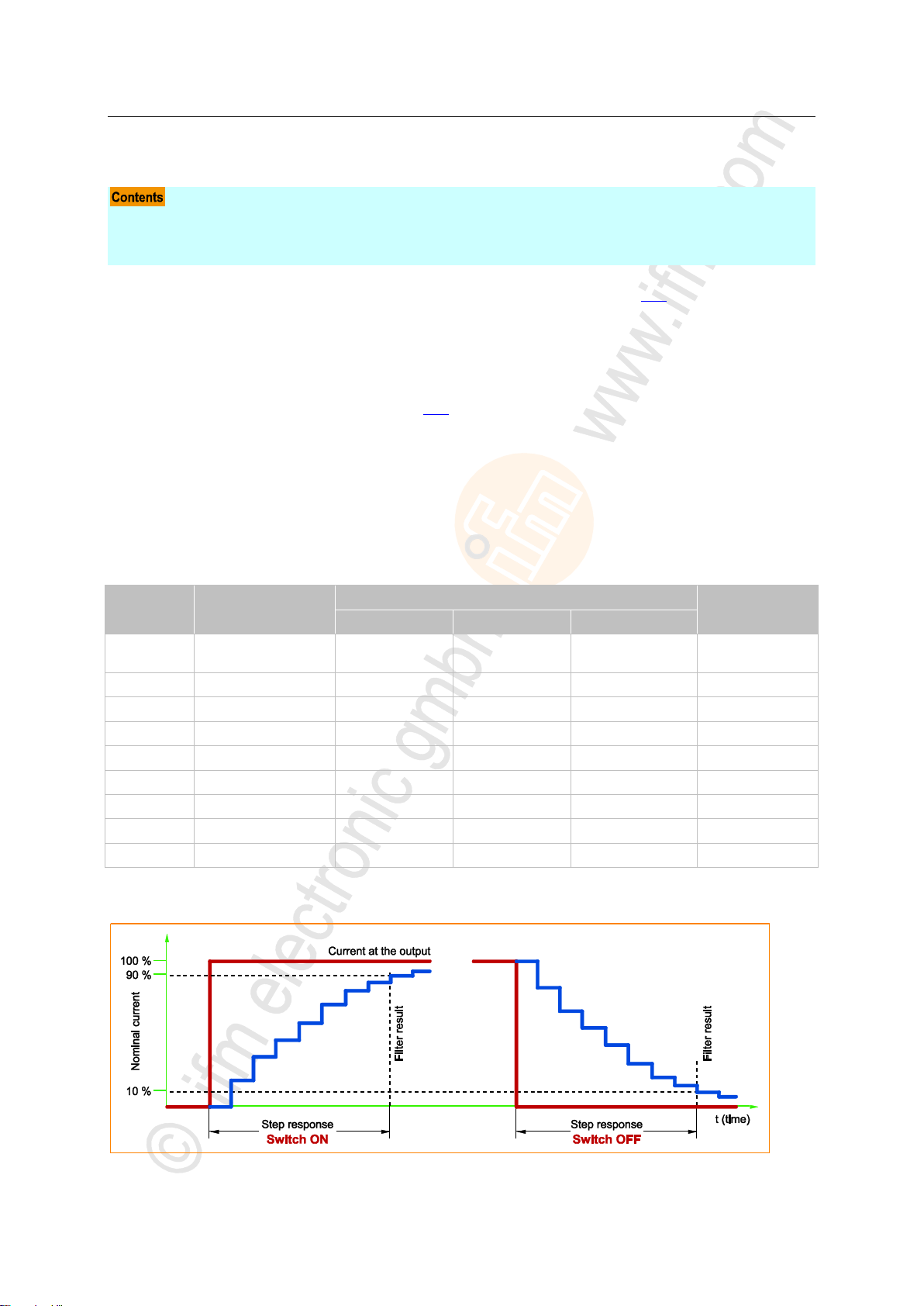
ifm Programming Manual BasicController relay CR0431 v03.03.00 05 / 2018
Configurations Function configuration of the inputs and outputs
4.4.3 Configure outputs
Configure the software filters of the outputs ...........................................................................................48
Relay outputs ..........................................................................................................................................49
LED outputs ............................................................................................................................................49
FILTER
Filter frequency [Hz]
Step response [ms] for ...
Remarks
0…90 %
0…95 %
0…99 %
0
Filter deactivated
outputs without current
measurement
1
600
0.8
1.0
1.4
2
233
1.8
2.2
3.4
3
109
3.6
4.6
7.0
4
52
7.2
9.4
14.4
recommended
5
26
14.6
19.0
29.2
6
13
29.4
38.2
58.6
7 6 58.8
76.4
117.6
8 4 117.8
153.2
235.4
3976
Valid operating modes → chapter Possible operating modes inputs/outputs (→ p. 206)
>
Configure the software filters of the outputs
15421
Via the input FILTER in the FB OUTPUT (→ p. 176) a software filter can be configured which filters the
measured output current at the PWM outputs.
The FILTER byte is only valid for outputs with current measurement.
For outputs without current measurement: set FILTER = 0!
The current at the output is averaged over a PWM period.
If dithering is set, the current is averaged over the dither period.
The filter behaves like a low-pass filter; the limit frequency is set by the value entered in FILTER. For
FILTER, values from 0...8 are permitted.
Table: limit frequency software low-pass filter on PWM output
The following statements of the step response are relevant:
• Output current: 0...90 % and 0...99 %
Figure: time sequence binary current signal on output upon switch-on / switch-off
48
Page 49

ifm Programming Manual BasicController relay CR0431 v03.03.00 05 / 2018
Configurations Function configuration of the inputs and outputs
>
Figure: Block diagram relay output
x = 0...n (depending on the device)
Relay outputs
The following operating modes are possible for the device outputs (→ data sheet):
• binary output with relay (change-over contacts)
• PWM output, plus switching (BH) without diagnostic function
Configuration of each output is made via the application program:
Binary output → FB OUTPUT (→ p. 176)> input MODE
PWM output: → FB PWM1000 (→ p. 178) (permissible PWM frequency = 15...25 kHz)
Relay output → FB RELAY (→ p. 180)
>
LED outputs
The LED outputs cannot be configured.
19693
19695
49
Page 50

ifm Programming Manual BasicController relay CR0431 v03.03.00 05 / 2018
Configurations Variables
>
Retain variables ......................................................................................................................................51
Network variables ...................................................................................................................................52
Variable
Declaration place
Validity area
Memory behaviour
local
in the declaration part of the function
element (POU)
Only valid in the function element
(POU) where it was configured.
volatile
local retain
nonvolatile
global
In [Resources] > [Global Variables] >
[Globale_Variables]:
Valid in all function elements of this
CODESYS project.
volatile
global retain
nonvolatile
Network
In [Resources] > [Global Variables] >
declaration list
Values are available to all CODESYS
projects in the whole network if the
variable is contained in its declaration
lists.
volatile
Network retain
nonvolatile
→ CODESYS programming manual
4.5 Variables
In this chapter you will learn more about how to handle variables.
The device supports the following types of variables:
3130
14486
50
Page 51
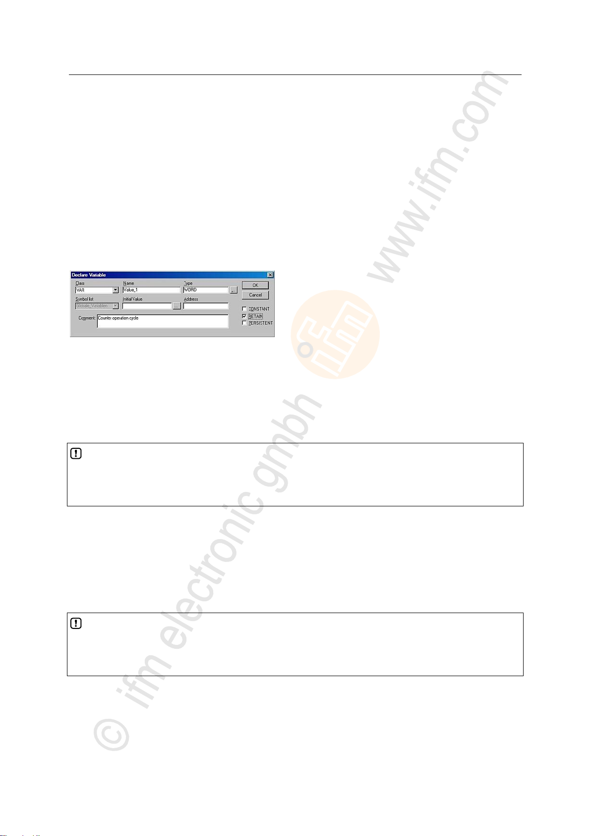
ifm Programming Manual BasicController relay CR0431 v03.03.00 05 / 2018
Configurations Variables
>
NOTE
In this device, do NOT use the following functions from the 3S library SysLibPlcCtrl.lib:
- FUN SysSaveRetains
- FUN SysRestoreRetains
NOTE
In this device, do NOT use the following functions from the 3S library SysLibPlcCtrl.lib:
- FUN SysSaveRetains
- FUN SysRestoreRetains
4.5.1 Retain variables
Retain variables can be saved automatically in a protected memory area and be reloaded
automatically during a reboot.
Typical applications for retain variables are for example:
• operating hours which are counted up and retained while the machine is in operation,
• position values of incremental encoders,
• preset values entered in the monitor,
• machine parameters,
i.e. all variables whose values must not get lost when the device is switched off.
All variable types, also complex structures (e.g. timers), can be declared as retain.
► To do so, activate the control field [RETAIN] in the variable declaration (→ window).
8672
14166
>
Save retain variables
9853
In the device the data type RETAIN is only stored in the volatile memory (RAM) during the runtime.
To save the data permanently, at the end of each cycle they are automatically be saved in the FRAM
memory ¹).
¹) FRAM indicates here all kinds of non-volatile and fast memories.
>
Read back retain variables
9854
After power on and before the first program cycle the device automatically writes the saved data back
to the working memory once. To do so, no additional FBs must be integrated into the application
program.
51
Page 52

ifm Programming Manual BasicController relay CR0431 v03.03.00 05 / 2018
Configurations Variables
>
4.5.2 Network variables
15242
9856
Global network variables are used for data exchange between controllers in the network. The values
of global network variables are available to all CODESYS projects in the whole network if the variables
are contained in their declaration lists.
► Integrate the following library/libraries into the CODESYS project:
3S_CANopenNetVar.lib
ifm_NetVarLib_NT_Vxxyyzz.lib
52
Page 53

ifm Programming Manual BasicController relay CR0431 v03.03.00 05 / 2018
ifm function elements ifm libraries for the device CR0431
5 ifm function elements
ifm libraries for the device CR0431 ........................................................................................................53
ifm function elements for the device CR0431.........................................................................................58
Library ifm_CR0431_V03yyzz.LIB .........................................................................................................54
Library ifm_CR0431_util_V03yyzz.LIB ...................................................................................................55
Library ifm_RAWCan_NT_Vxxyyzz.LIB .................................................................................................55
Library ifm_CANopen_NT_Vxxyyzz.LIB .................................................................................................56
Library ifm_J1939_NT_Vxxyyzz.LIB ......................................................................................................57
13586
All CODESYS function elements (FBs, PRGs, FUNs) are stored in libraries. Below you will find a list of
all the ifm libraries you can use with this device.
This is followed by a description of the function elements, sorted by topic.
5.1 ifm libraries for the device CR0431
14235
53
Page 54

ifm Programming Manual BasicController relay CR0431 v03.03.00 05 / 2018
ifm function elements ifm libraries for the device CR0431
>
Function element
Short description
FASTCOUNT (→ p. 165)
Counter block for fast input pulses
FLASH_INFO (→ p. 183)
Reads the information from the user flash memory:
• name of the memory area (user defined),
• software version,
• start address (for simple reading with IEC structure)
FLASH_READ (→ p. 184)
transfers different data types directly from the flash memory to the RAM
GET_APP_INFO (→ p. 185)
Delivers information about the application program stored in the device:
• name of the application,
• version of the application,
• unique CODESYS build number,
• CODESYS build date
GET_HW_INFO (→ p. 186)
Delivers information about the device hardware:
• ifm article number (e.g. CR0403),
• article designation,
• unambiguous serial number,
• hardware revision,
• production date
GET_IDENTITY (→ p. 187)
Reads the identification of the application stored in the device
(has previously been saved by means of SET_IDENTITY (→ p. 195))
GET_SW_INFO (→ p. 188)
Delivers information about the system software of the device:
• software name,
• software version,
• build number,
• build date
GET_SW_VERSION (→ p. 189)
Delivers information about the software versions stored in the device:
• BasicSystem version,
• bootloader version,
• SIS version,
• application program version,
• user flash version
INC_ENCODER (→ p. 167)
Up/down counter function for the evaluation of encoders
INPUT (→ p. 169)
Assigns an operating mode to an input channel
Provides the current state of the selected channel
MEM_ERROR (→ p. 190)
Signals errors in some parameters or in the memory
(Re-)initialisation of system resources
MEMCPY (→ p. 191)
Writes and reads different data types directly in the memory
OHC (→ p. 193)
Adjustable operating hours counter (0...3)
OUTPUT (→ p. 176)
Assigns an operating mode to an output channel
Provides the current state of the selected channel
PERIOD (→ p. 171)
Measures the frequency and the cycle period (cycle time) in [µs] at the indicated channel
PWM1000 (→ p. 178)
Initialises and configures a PWM-capable output channel
the mark-to-space ratio can be indicated in steps of 1 ‰
SET_IDENTITY (→ p. 195)
Sets an application-specific program identification
SET_LED (→ p. 196)
Change the frequency and color of the status LED in the application program
SET_PASSWORD (→ p. 198)
Sets a user password for access control to program and memory upload
TIMER_READ_US (→ p. 199)
Reads out the current system time in [µs]
Max. value = 1h 11min 34s 967ms 295µs
5.1.1 Library ifm_CR0431_V03yyzz.LIB
This is the device library. This ifm library contains the following function blocks:
19699
54
Page 55

ifm Programming Manual BasicController relay CR0431 v03.03.00 05 / 2018
ifm function elements ifm libraries for the device CR0431
>
Function element
Short description
RELAY (→ p. 180)
switches the relay of the selected output channel with an adjustable voltage
STATUS_F_V_EXT (→ p. 174)
determines the status of the fuse for the potential V_EXT
Function element
Short description
CAN_ENABLE (→ p. 61)
Initialises the indicated CAN interface
Configures the CAN baud rate
CAN_RECOVER (→ p. 62)
Activate / deactivate the automatic bus off handling
Restart the CAN interface in case of bus off
CAN_REMOTE_REQUEST (→ p. 83)
Send a corresponding request and return the response of the other device as a result
CAN_REMOTE_RESPONSE (→ p. 84)
Provides data to the CAN controller in the device which is automatically sent as a response to the
request of a remote message
CAN_RX (→ p. 67)
Configures a data receive object and reads out the receive buffer of the data object
CAN_RX_ENH (→ p. 68)
• Configures a data receive object and reads out the receive buffer of the data object
• Frame type and mask can be selected
CAN_RX_ENH_FIFO (→ p. 70)
• Configures a data receive object and reads out the receive buffer of the data object
• Frame type and mask can be selected
• Several CAN messages per cycle possible
CAN_RX_RANGE (→ p. 72)
• Configures a range of data receive objects and reads out the receive buffer of the data objects
• Frame type and mask can be selected
CAN_RX_RANGE_FIFO (→ p. 74)
• Configures a range of data receive objects and reads out the receive buffer of the data objects
• Frame type and mask can be selected
• Several CAN messages per cycle possible
CAN_SETDOWNLOADID (→ p. 63)
= Set CAN download ID
Sets the download identifier for the CAN interface
CAN_STATUS (→ p. 64)
Get status information on the CAN bus selected:
BAUDRATE, DOWNLOAD_ID, BUSOFF, WARNING_RX, WARNING_TX, VERSION, BUSLOAD
and reset if required: BUSOFF, WARNING_RX, WARNING_TX
CAN_TX (→ p. 77)
Transfers a CAN data object (message) to the configured CAN interface for transmission at each
call
CAN_TX_ENH (→ p. 78)
Transfers a CAN data object (message) to the configured CAN interface for transmission at each
call
CAN-specific characteristics can be set
CAN_TX_ENH_CYCLIC (→ p. 80)
Cyclically transfers a CAN data object (message) to the configured CAN interface for
transmission
CAN-specific characteristics can be set
5.1.2 Library ifm_CR0431_util_V03yyzz.LIB
This ifm library contains the following function blocks:
>
5.1.3 Library ifm_RAWCan_NT_Vxxyyzz.LIB
This ifm library contains the following function blocks:
19735
14715
55
Page 56

ifm Programming Manual BasicController relay CR0431 v03.03.00 05 / 2018
ifm function elements ifm libraries for the device CR0431
>
Function element
Short description
CANOPEN_ENABLE (→ p. 87)
Initialises the indicated CANopen master interface
Configures the CAN baud rate
CANOPEN_GETBUFFERFLAGS (→ p. 89)
= CANopen get buffer flags
Provides information on the buffer flags
The flags can be reset via the optional inputs.
CANOPEN_GETEMCYMESSAGES (→ p. 126)
= Get CANopen emergency messages
Lists all emergency messages that have been received by the controller from other nodes in the
network since the last deletion of messages
The list can be reset by setting the according input.
CANOPEN_GETERRORREGISTER (→ p. 128)
= Get CANopen error register
Reads the error registers 0x1001 and 0x1003 from the controller
The registers can be reset by setting the respective inputs.
CANOPEN_GETGUARDHBERRLIST (→ p. 122)
= get CANopen guard and heartbeat error list
Lists all nodes in an array for which the master has detected an error:
guarding error, heartbeat error
The list can be reset by setting the according input.
CANOPEN_GETGUARDHBSTATSLV (→ p. 123)
= CANopen slave get guard and heartbeat state
Signals the following states to the controller in slave operation:
node guarding monitoring, heartbeat monitoring
The signalled errors can be reset by setting the respective input.
CANOPEN_GETNMTSTATESLAVE (→ p. 96)
= CANopen slave get network management state
Signals the network operating status of the node
CANOPEN_GETODCHANGEDFLAG (→ p. 100)
= Get object directory changed flag
Reports any change of value for a particular object directory entry
CANOPEN_GETSTATE (→ p. 91)
= CANopen set state
Request the parameters of the master, a slave device or a specific node in the network
CANOPEN_GETSYNCSTATE (→ p. 118)
= CANopen get SYNC state
• Reads the setting of the SYNC functionality (active / not active),
• reads the error state of the SYNC functionality (SyncError)
CANOPEN_NMTSERVICES (→ p. 97)
= CANopen network management services
Updates the internal node status
and, depending on the NMT command entries:
• triggers an NMT command or
• triggers the initialisation of a node
CANOPEN_READOBJECTDICT (→ p. 101)
= CANopen read object directory
Reads configuration data from the object directory of the device
CANOPEN_SDOREAD (→ p. 105)
= CANopen read SDO
Reads an "Expedited SDO" = Expedited Service Data Object
CANOPEN_SDOREADBLOCK (→ p. 107)
= CANopen read SDO block
Reads the indicated entry in the object directory of a node in the network via SDO block transfer
CANOPEN_SDOREADMULTI (→ p. 109)
= CANopen read SDO multi
Reads the indicated entry in the object directory of a node in the network
CANOPEN_SDOWRITE (→ p. 111)
= SDO write
Writes an "Expedited SDO" = Expedited Service Data Object
CANOPEN_SDOWRITEBLOCK (→ p. 113)
= CANopen write SDO block
Writes in the indicated entry in the object directory of a node in the network via SDO block
transfer
CANOPEN_SDOWRITEMULTI (→ p. 115)
= CANopen write SDO multi
Writes in the indicated entry in the object directory of a node in the network
CANOPEN_SENDEMCYMESSAGE (→ p. 130)
= CANopen send emergency message
Sends an EMCY message. The message is assembled from the according parameters and
entered in register 0x1003
5.1.4 Library ifm_CANopen_NT_Vxxyyzz.LIB
This ifm library contains the following function blocks:
14914
56
Page 57

ifm Programming Manual BasicController relay CR0431 v03.03.00 05 / 2018
ifm function elements ifm libraries for the device CR0431
Function element
Short description
CANOPEN_SETSTATE (→ p. 93)
= CANopen set state
Set the parameters of the master, a slave device or a specific node in the network
CANOPEN_SETSYNCSTATE (→ p. 120)
= CANopen set SYNC state
Switch the SYNC functionality on and off
CANOPEN_WRITEOBJECTDICT (→ p. 102)
= CANopen write object directory
Writes configuration data into the object directory of the device
Function element
Short description
J1939_DM1RX (→ p. 157)
J1939 Diagnostic Message 1 RX
Receives diagnostic messages DM1 or DM2 from other ECUs
J1939_DM1TX (→ p. 159)
J1939 Diagnostic Message 1 TX
Transmit an active error message to the CAN stack
J1939_DM1TX_CFG (→ p. 162)
J1939 Diagnostic Message 1 TX configurable
CAN stack does not send cyclic DM1 "zero active faults" messages
J1939_DM3TX (→ p. 163)
J1939 Diagnostic Message 3 TX
Deletes inactive DTCs (DM2) on a device
J1939_ENABLE (→ p. 133)
Initialises the J1939 stack
J1939_GETDABYNAME (→ p. 135)
= Get destination arbitrary name
Determine the target address of one or several participants by means of the name information
J1939_NAME (→ p. 137)
Give the device a name for identification in the network
J1939_RX (→ p. 144)
Receives a single frame message
Shows the message last read on the CAN bus
J1939_RX_FIFO (→ p. 145)
= J1939 RX with FIFO
Receives all specific messages and successively reads them from a FiFo
J1939_RX_MULTI (→ p. 147)
= J1939 RX multiframe message
Receives multiframe messages
J1939_SPEC_REQ (→ p. 141)
= J1939 specific request
Requests and receives a specific message from another controller
J1939_SPEC_REQ_MULTI (→ p. 142)
= J1939 specific request multiframe message
Requests and receives a specific multiframe message from another controller
J1939_STATUS (→ p. 139)
Shows relevant information on the J1939 stack
J1939_TX (→ p. 149)
Sends individual single frame messages
J1939_TX_ENH (→ p. 150)
= J1939 TX enhanced
Sends individual single frame messages
Can also be set: transmission priority, data length
J1939_TX_ENH_CYCLIC (→ p. 152)
= J1939 TX enhanced cyclic
Cyclically sends single frame messages
Can also be set: transmission priority, data length, period
J1939_TX_ENH_MULTI (→ p. 154)
= J1939 TX enhanced Multiframe Message
Sends individual multiframe messages
>
5.1.5 Library ifm_J1939_NT_Vxxyyzz.LIB
This ifm library contains the following function blocks:
14912
57
Page 58

ifm Programming Manual BasicController relay CR0431 v03.03.00 05 / 2018
ifm function elements ifm function elements for the device CR0431
>
Function element outputs .......................................................................................................................59
Function elements: RAW-CAN (Layer 2) ...............................................................................................60
Function elements: CANopen ................................................................................................................86
Function elements: SAE J1939 ............................................................................................................132
Function elements: processing input values ........................................................................................164
Function elements: output functions .....................................................................................................175
Function elements: system ...................................................................................................................182
5.2 ifm function elements for the device CR0431
13988
3826
Here you will find the description of the ifm function elements suitable for this device, sorted by topic.
58
Page 59

ifm Programming Manual BasicController relay CR0431 v03.03.00 05 / 2018
ifm function elements ifm function elements for the device CR0431
>
Value
dec | hex
Description
0
00
FB is inactive
1...31
Global return values; examples:
1
01
FB execution completed without error – data is valid
4
04
FB is being processed – data is cyclically processed
5
05
FB is being processed – still receiving
6
06
FB is being processed – still sending
7
07
FB is being processed – remote for ID active
8
08
function block is active
14
0E
FB is active
CANopen manager configures devices and sends SDOs
15
0F
FB is active
CANopen manager is started
3210...63
FB specific return values
6410…127
FB specific error messages
12810...255
Global error messages; examples:
238
EE
Error: CANopen configuration is too large and cannot be started
239
EF
Error: CANopen manager could not be started
240
F0
Error: several modal inputs are active
e.g. CANopen NTM services
241
F1
Error: CANopen state transition is not permitted
242
F2
Error: setting is not possible
247
F7
Error: memory exceeded (length larger than array)
250
FA
Error: FiFo is full – data was lost
252
FC
Error: CAN multiframe transmission failed
253
FD
Error: CAN transmission failed.
Data cannot be sent.
255
FF
Error: not enough memory available for the consuming multiframe
5.2.1 Function element outputs
Some function elements return a RESULT message.
Possible results for RESULT:
8354
7556
59
Page 60

ifm Programming Manual BasicController relay CR0431 v03.03.00 05 / 2018
ifm function elements ifm function elements for the device CR0431
>
Function elements: RAW-CAN status ....................................................................................................60
Function elements: receive RAW-CAN data ..........................................................................................66
Function elements: transmit RAW-CAN data .........................................................................................76
Function elements: RAW-CAN remote ...................................................................................................82
CAN_ENABLE ........................................................................................................................................61
CAN_RECOVER ....................................................................................................................................62
CAN_SETDOWNLOADID ......................................................................................................................63
CAN_STATUS ........................................................................................................................................64
5.2.2 Function elements: RAW-CAN (Layer 2)
Here we describe the RAW-CAN function blocks (CAN Layer 2) of ifm electronic to be used in the
application program.
Function elements: RAW-CAN status
15051
15049
60
Page 61

ifm Programming Manual BasicController relay CR0431 v03.03.00 05 / 2018
ifm function elements ifm function elements for the device CR0431
>
Parameter
Data type
Description
ENABLE
BOOL := FALSE
TRUE: enable CAN interface
FALSE: disable CAN interface
CHANNEL
BYTE
CAN interface (1...n) depending on the device
BAUDRATE
WORD := 250
Baudrate [kbits/s]
permissible = 20, 50, 100, 125, 250, 500, 1000
Parameter
Data type
Description
RESULT
BYTE
feedback of the function block
(possible messages → following table)
Value
dec | hex
Description
0
00
FB is inactive
1
01
FB execution completed without error – data is valid
8
08
function block is active
9
09
CAN is not active
242
F2
Error: setting is not possible
CAN_ENABLE
Unit type = function block (FB)
Unit is contained in the library ifm_RawCAN_NT_Vxxyyzz.LIB
Symbol in CODESYS:
7492
>
Description
With CAN_ENABLE the CAN hardware is initialised. Without this call no other calls are possible in
RAW-CAN or they return an error.
In order to change the baud rate the following procedure is required:
► Maintain the function block on ENABLE=FALSE for the duration of one cycle.
> All protocols are reset.
> Re-initialisation of the CAN interface and the CAN protocols running on it. Any information
available for cyclical transmission is lost as well and must be newly created.
> At renewed ENABLE=TRUE, the new baud rate is adopted.
>
Parameters of the inputs
>
7494
7495
Parameters of the outputs
Possible results for RESULT:
61
8530
Page 62

ifm Programming Manual BasicController relay CR0431 v03.03.00 05 / 2018
ifm function elements ifm function elements for the device CR0431
CAN_RECOVER
Parameter
Data type
Description
ENABLE
BOOL := FALSE
TRUE: No automatic recovery after CAN bus off
FALSE: Automatic recovery after CAN bus off
CHANNEL
BYTE
CAN interface (1...n) depending on the device
RECOVER_EXECUTE
BOOL
TRUE (only for 1 cycle):
restart of CAN interface
remedy bus off condition
FALSE: function element is not executed
InhibitTime
(optional use of the parameter)
TIME := T#1s
Waiting time between bus off and restart of the CAN interface
Unit type = function block (FB)
Unit is contained in the library ifm_RawCAN_NT_Vxxyyzz.LIB
Symbol in CODESYS:
7512
>
Description
7513
CAN_RECOVER has the following tasks:
to activate / deactivate the automatic bus off handling
to restart the CAN interface in case of bus off
> In case of bus off: CAN Controller deletes all buffers (including the buffers of the other protocols).
If CAN_RECOVER is not used (ENABLE=FALSE):
> in case of a bus off a recovery attempt is automatically made after 1 s.
> after 4 failed recovery attempts in a row the affected CAN interface is deactivated.
>
Parameters of the inputs
7514
62
Page 63

ifm Programming Manual BasicController relay CR0431 v03.03.00 05 / 2018
ifm function elements ifm function elements for the device CR0431
CAN_SETDOWNLOADID
Parameter
Data type
Description
EXECUTE
BOOL := FALSE
FALSE TRUE (edge):
execute function element once
otherwise: function element is not active
A function element already started is processed.
CHANNEL
BYTE
CAN interface (1...n) depending on the device
DOWNLOAD_ID
BYTE
1...127 = set download ID
0 = read download ID
Parameter
Data type
Description
RESULT
BYTE
feedback of the function block
(possible messages → following table)
Value
dec | hex
Description
0
00
FB is inactive
1
01
function block execution completed without error
8
08
function block is active
242
F2
Error: setting is not possible
= Set download ID
Unit type = function block (FB)
Unit is contained in the library ifm_RawCAN_NT_Vxxyyzz.LIB
Symbol in CODESYS:
7516
>
Description
The download ID is required for data exchange when connecting the runtime system and the
CODESYS development environment. When the device is started the download ID is set with the
default value from the hardware configuration.
With CAN_SETDOWNLOADID this value can be set in the PLC program (e.g. using certain inputs).
The changed ID is also written into the hardware configuration.
>
Parameters of the inputs
>
Parameters of the outputs
7517
7519
7520
Possible results for RESULT:
63
Page 64
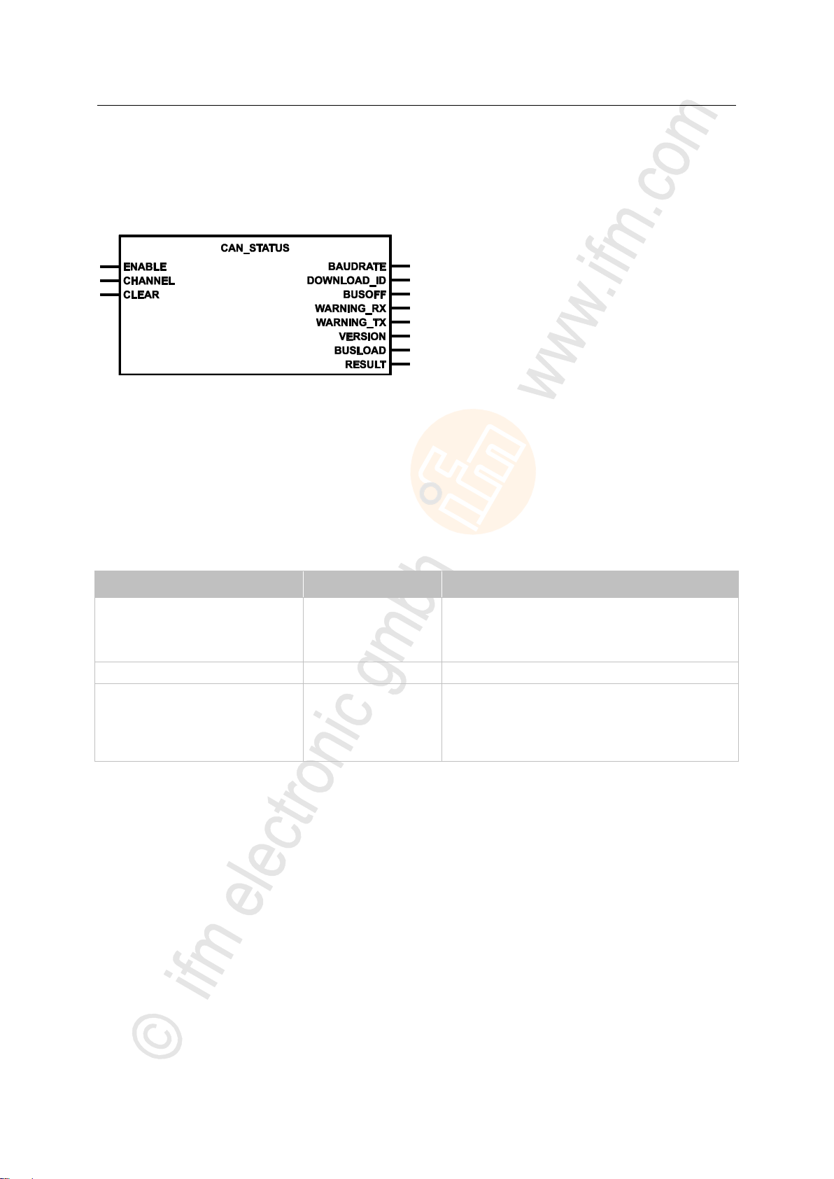
ifm Programming Manual BasicController relay CR0431 v03.03.00 05 / 2018
ifm function elements ifm function elements for the device CR0431
CAN_STATUS
Parameter
Data type
Description
ENABLE
BOOL := FALSE
TRUE: execute this function element
FALSE: unit is not executed
> Function block inputs are not active
> Function block outputs are not specified
CHANNEL
BYTE
CAN interface (1...n) depending on the device
CLEAR
BOOL := FALSE
TRUE: Reset the following flags:
• WARNING_RX
• WARNING_TX
• BUSOFF
FALSE: function element is not executed
Unit type = function block (FB)
Unit is contained in the library ifm_RawCAN_NT_Vxxyyzz.LIB
Symbol in CODESYS:
7499
>
Description
CAN_STATUS provides information on the chosen CAN bus.
Without hardware initialisation the following flags can be reset to FALSE:
- BUSOFF
- WARNING_RX
- WARNING_TX
>
Parameters of the inputs
7501
7502
64
Page 65

ifm Programming Manual BasicController relay CR0431 v03.03.00 05 / 2018
ifm function elements ifm function elements for the device CR0431
>
Parameter
Data type
Description
BAUDRATE
WORD
current baudrate of the CANopen node in [kBaud]
DOWNLOAD_ID
BYTE
current download ID
BUSOFF
BOOL
Error CAN BUS OFF at the interface
WARNING_RX
BOOL
Warning threshold for receiving is exceeded at the interface
WARNING_TX
BOOL
Warning threshold for transmitting is exceeded at the interface
VERSION
DWORD
Version of the ifm CAN stack library
BUSLOAD
BYTE
Current bus load in [%]
RESULT
BYTE
feedback of the function block
(possible messages → following table)
Value
dec | hex
Description
0
00
FB is inactive
1
01
function block execution completed without error
8
08
function block is active
9
09
CAN is not active
242
F2
Error: setting is not possible
Parameters of the outputs
Possible results for RESULT:
7504
65
Page 66

ifm Programming Manual BasicController relay CR0431 v03.03.00 05 / 2018
ifm function elements ifm function elements for the device CR0431
Function elements: receive RAW-CAN data
CAN_RX .................................................................................................................................................67
CAN_RX_ENH .......................................................................................................................................68
CAN_RX_ENH_FIFO .............................................................................................................................70
CAN_RX_RANGE ..................................................................................................................................72
CAN_RX_RANGE_FIFO ........................................................................................................................74
15050
66
Page 67

ifm Programming Manual BasicController relay CR0431 v03.03.00 05 / 2018
ifm function elements ifm function elements for the device CR0431
CAN_RX
Parameter
Data type
Description
ENABLE
BOOL
TRUE: execute this function element
FALSE: unit is not executed
> Function block inputs are not active
> Function block outputs are not specified
CHANNEL
BYTE
CAN interface (1...n) depending on the device
ID
DWORD
Number of the data object identifier:
normal frame (2 048 IDs):
0...2 047 = 0x0000 0000...0x0000 07FF
extended Frame (536 868 864 IDs):
2 048...536 870 911 = 0x0000 0800...0x1FFF FFFF
Parameter
Data type
Description
DATA
ARRAY [0..7] OF BYTE
received data, (1...8 bytes)
RESULT
BYTE
feedback of the function block
(possible messages → following table)
Value
dec | hex
Description
0
00
FB is inactive
1
01
function block execution completed without error
5
05
FB is being processed – still receiving
9
09
CAN is not active
242
F2
Error: setting is not possible
Unit type = function block (FB)
Unit is contained in the library ifm_RawCAN_NT_Vxxyyzz.LIB
Symbol in CODESYS:
7586
>
Description
7588
CAN_RX is used for receiving a message.
The FB limits itself to a few functions and the required memory space is low.
CAN_RX filters for the set identifier. If several CAN messages with the same identifier are received in
one cycle, only the last / latest message is available.
>
Parameters of the inputs
7589
>
Parameters of the outputs
Possible results for RESULT:
67
7590
Page 68
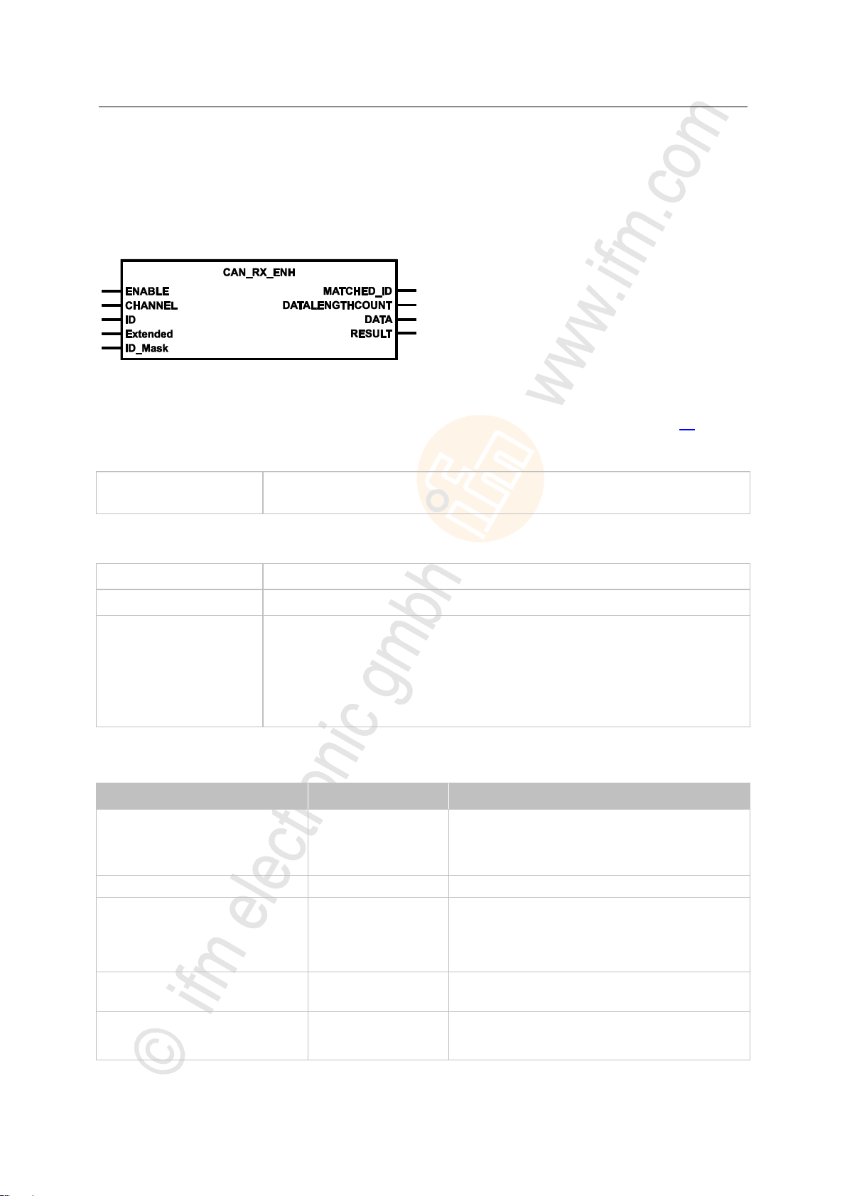
ifm Programming Manual BasicController relay CR0431 v03.03.00 05 / 2018
ifm function elements ifm function elements for the device CR0431
CAN_RX_ENH
Bit comparison of
ID and mask:
If ID_MASK-Bit = 0, then CAN-ID-Bit may be = 0 or 1.
If ID_MASK-Bit = 1, then CAN-ID-Bit must be = ID-Bit.
ID =
0x100 = 0b0001 0000 0000
ID_MASK =
0x1F1 = 0b0001 1111 0001
Result
The CAN IDs with the following bit pattern are evaluated:
0bxxx1 0000 xxx0 (x = any), i.e. for this example (all in [hex]):
100, 102, 104, 106, 108, 10A, 10C, 10E,
300, 302, 304, 306, 308, 30A, 30C, 30E,
500, 502, 504, 506, 508, 50A, 50C, 50E,
700, 702, 704, 706, 708, 70A, 70C, 70E
Parameter
Data type
Description
ENABLE
BOOL
TRUE: execute this function element
FALSE: unit is not executed
> Function block inputs are not active
> Function block outputs are not specified
CHANNEL
BYTE
CAN interface (1...n) depending on the device
ID
DWORD
Number of the data object identifier:
normal frame (211 IDs):
0...2 047 = 0x0000 0000...0x0000 07FF
extended Frame (229 IDs):
0...536 870 911 = 0x0000 0000...0x1FFF FFFF
Extended
(optional use of the parameter)
BOOL := FALSE
TRUE: extended Frame (ID = 0...229-1)
FALSE: normal Frame (ID = 0...211-1)
ID_Mask
(optional use of the parameter)
DWORD := 0
filter mask for the identifier:
if ID_MASK bit = 0, CAN ID bit may be = 0 or 1
if ID_MASK bit = 1, CAN ID bit must be = ID bit
= CAN RX enhanced
Unit type = function block (FB)
Unit is contained in the library ifm_RawCAN_NT_Vxxyyzz.LIB
Symbol in CODESYS:
7606
>
Description
In addition, CAN_RX_ENH provides the following possibilities (as opposed to CAN_RX (→ p. 67)):
• select the frame type (11 or 29 bits),
• define a mask for the evaluation of the CAN ID.
With the mask several identifiers can be defined as filters.
Example:
>
Parameters of the inputs
7608
7609
68
Page 69

ifm Programming Manual BasicController relay CR0431 v03.03.00 05 / 2018
ifm function elements ifm function elements for the device CR0431
>
Parameter
Data type
Description
MATCHED_ID
DWORD
number of the data object identifier
DATALENGTHCOUNT
BYTE
= Data Length Count
number of the data bytes received
DATA
ARRAY [0..7] OF BYTE
received data, (1...8 bytes)
RESULT
BYTE
feedback of the function block
(possible messages → following table)
Value
dec | hex
Description
0
00
FB is inactive
1
01
function block execution completed without error
5
05
FB is being processed – still receiving
9
09
CAN is not active
242
F2
Error: setting is not possible
Parameters of the outputs
Possible results for RESULT:
7613
69
Page 70

ifm Programming Manual BasicController relay CR0431 v03.03.00 05 / 2018
ifm function elements ifm function elements for the device CR0431
CAN_RX_ENH_FIFO
No overwriting takes place when the FiFo is full. Inbound messages will be lost.
Parameter
Data type
Description
ENABLE
BOOL
TRUE: execute this function element
FALSE: unit is not executed
> Function block inputs are not active
> Function block outputs are not specified
CHANNEL
BYTE
CAN interface (1...n) depending on the device
ID
DWORD
Number of the data object identifier:
normal frame (211 IDs):
0...2 047 = 0x0000 0000...0x0000 07FF
extended Frame (229 IDs):
0...536 870 911 = 0x0000 0000...0x1FFF FFFF
Extended
(optional use of the parameter)
BOOL := FALSE
TRUE: extended Frame (ID = 0...229-1)
FALSE: normal Frame (ID = 0...211-1)
ID_Mask
(optional use of the parameter)
DWORD := 0
filter mask for the identifier:
if ID_MASK bit = 0, CAN ID bit may be = 0 or 1
if ID_MASK bit = 1, CAN ID bit must be = ID bit
= CAN RX enhanced with FiFo
Unit type = function block (FB)
Unit is contained in the library ifm_RawCAN_NT_Vxxyyzz.LIB
Symbol in CODESYS:
7615
>
Description
In addition, CAN_RX_ENH_FIFO provides a FiFo for the received data (as opposed to CAN_RX_ENH
(→ p. 68)). Thus several CAN messages can be received in one cycle.
In this event:
► Deactivate and reactive the FB via ENABLE.
> The FiFo is deleted and can be newly filled.
Description to the filter mask: → CAN_RX_ENH (→ p. 68) > chapter Description
>
Parameters of the inputs
7616
7609
70
Page 71

ifm Programming Manual BasicController relay CR0431 v03.03.00 05 / 2018
ifm function elements ifm function elements for the device CR0431
>
Parameter
Data type
Description
MATCHED_ID
DWORD
number of the data object identifier
DATALENGTHCOUNT
BYTE
= Data Length Count
number of the data bytes received
DATA
ARRAY [0..7] OF BYTE
received data, (1...8 bytes)
MORE_DATA_AVAILABLE
BOOL
TRUE: further received data available in the FiFo
FALSE: no further data available in the FiFo
RESULT
BYTE
feedback of the function block
(possible messages → following table)
Value
dec | hex
Description
0
00
FB is inactive
1
01
function block execution completed without error
5
05
FB is being processed – still receiving
9
09
CAN is not active
242
F2
Error: setting is not possible
250
FA
Error: FiFo is full – data was lost
Parameters of the outputs
Possible results for RESULT:
7617
71
Page 72
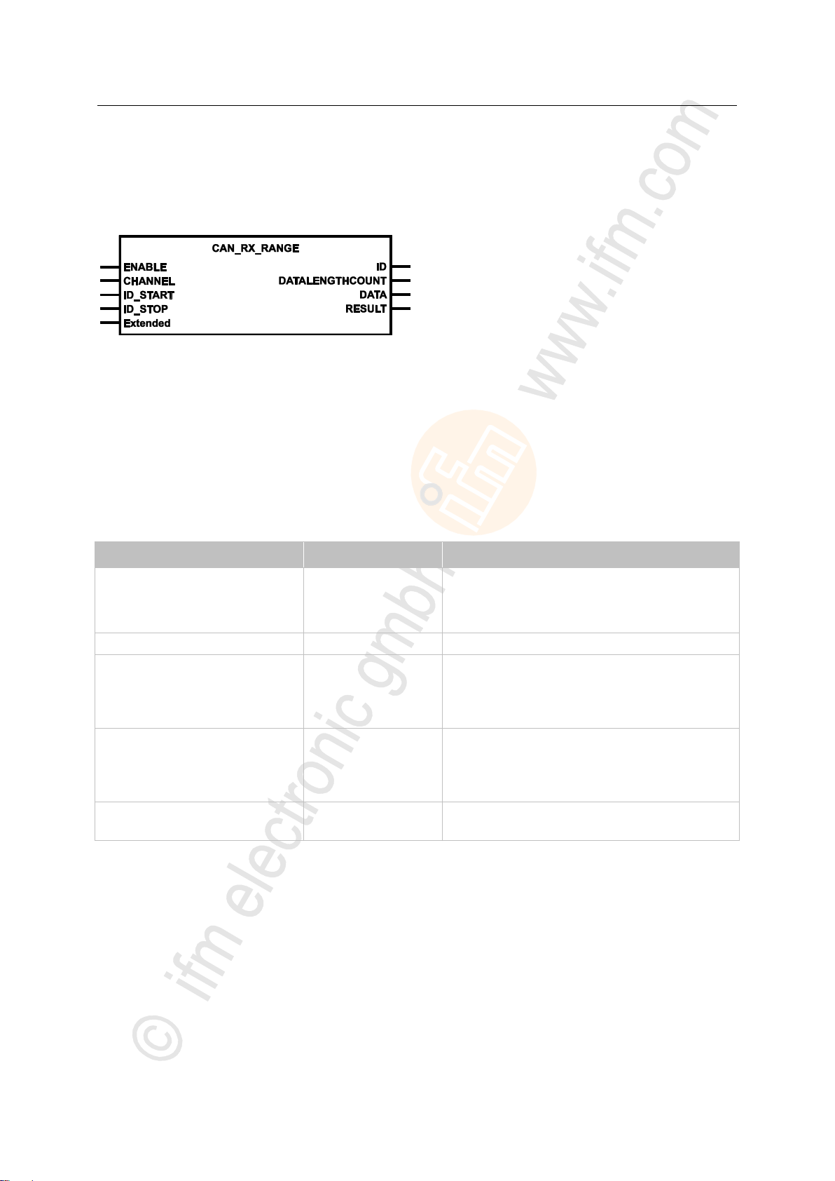
ifm Programming Manual BasicController relay CR0431 v03.03.00 05 / 2018
ifm function elements ifm function elements for the device CR0431
CAN_RX_RANGE
Parameter
Data type
Description
ENABLE
BOOL
TRUE: execute this function element
FALSE: unit is not executed
> Function block inputs are not active
> Function block outputs are not specified
CHANNEL
BYTE
CAN interface (1...n) depending on the device
ID_START
DWORD
start number of the data object identifier range:
normal frame (211):
0...2 047 = 0x0000 0000...0x0000 07FF
extended frame (229):
0...536 870 911 = 0x0000 0000...0x1FFF FFFF
ID_STOP
DWORD
end number of the data object identifier range:
normal frame (211):
0...2 047 = 0x0000 0000...0x0000 07FF
extended frame (229):
0...536 870 911 = 0x0000 0000...0x1FFF FFFF
Extended
(optional use of the parameter)
BOOL := FALSE
TRUE: extended Frame (ID = 0...229-1)
FALSE: normal Frame (ID = 0...211-1)
Unit type = function block (FB)
Unit is contained in the library ifm_RawCAN_NT_Vxxyyzz.LIB
Symbol in CODESYS:
7592
>
Description
7594
CAN_RX_RANGE provides the following settings:
select the message type (11 or 29 bits),
define an identifier range.
CAN_RX filters for the set identifier. If several CAN messages with the same identifier are received in
one cycle, only the last / latest message is available.
>
Parameters of the inputs
7595
72
Page 73

ifm Programming Manual BasicController relay CR0431 v03.03.00 05 / 2018
ifm function elements ifm function elements for the device CR0431
>
Parameter
Data type
Description
ID
DWORD
Number of the data object identifier:
normal frame (2 048 IDs):
0...2 047 = 0x0000 0000...0x0000 07FF
extended Frame (536 868 864 IDs):
2 048...536 870 911 = 0x0000 0800...0x1FFF FFFF
DATALENGTHCOUNT
BYTE
= Data Length Count
number of the data bytes received
DATA
ARRAY [0..7] OF BYTE
received data, (1...8 bytes)
RESULT
BYTE
feedback of the function block
(possible messages → following table)
Value
dec | hex
Description
0
00
FB is inactive
1
01
function block execution completed without error
5
05
FB is being processed – still receiving
9
09
CAN is not active
242
F2
Error: setting is not possible
Parameters of the outputs
Possible results for RESULT:
7598
73
Page 74
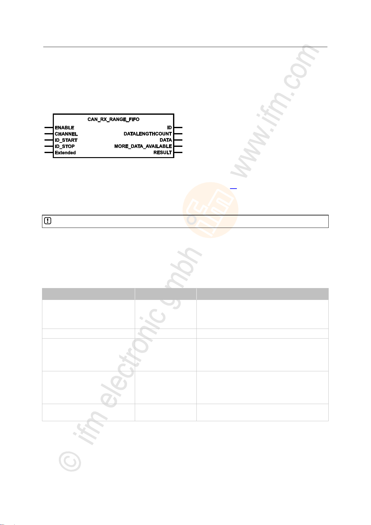
ifm Programming Manual BasicController relay CR0431 v03.03.00 05 / 2018
ifm function elements ifm function elements for the device CR0431
CAN_RX_RANGE_FIFO
No overwriting takes place when the FiFo is full. Inbound messages will be lost.
Parameter
Data type
Description
ENABLE
BOOL
TRUE: execute this function element
FALSE: unit is not executed
> Function block inputs are not active
> Function block outputs are not specified
CHANNEL
BYTE
CAN interface (1...n) depending on the device
ID_START
DWORD
start number of the data object identifier range:
normal frame (211):
0...2 047 = 0x0000 0000...0x0000 07FF
extended frame (229):
0...536 870 911 = 0x0000 0000...0x1FFF FFFF
ID_STOP
DWORD
end number of the data object identifier range:
normal frame (211):
0...2 047 = 0x0000 0000...0x0000 07FF
extended frame (229):
0...536 870 911 = 0x0000 0000...0x1FFF FFFF
Extended
(optional use of the parameter)
BOOL := FALSE
TRUE: extended Frame (ID = 0...229-1)
FALSE: normal Frame (ID = 0...211-1)
= CAN RX range with FiFo
Unit type = function block (FB)
Unit is contained in the library ifm_RawCAN_NT_Vxxyyzz.LIB
Symbol in CODESYS:
7601
>
Description
CAN_RX_RANGE_FIFO basically works like CAN_RX_RANGE (→ p. 72).
In addition, CAN_RX_RANGE_FIFO provides a FiFo for the received data. Thus several CAN
messages can be received in one cycle.
In this event:
► Use ENABLE to deactivate and reactivate the function.
> The FiFo is deleted and can be newly filled.
>
Parameters of the inputs
7603
7595
74
Page 75

ifm Programming Manual BasicController relay CR0431 v03.03.00 05 / 2018
ifm function elements ifm function elements for the device CR0431
>
Parameter
Data type
Description
ID
DWORD
Number of the data object identifier:
normal frame (2 048 IDs):
0...2 047 = 0x0000 0000...0x0000 07FF
extended Frame (536 868 864 IDs):
2 048...536 870 911 = 0x0000 0800...0x1FFF FFFF
DATALENGTHCOUNT
BYTE
= Data Length Count
number of the data bytes received
DATA
ARRAY [0..7] OF BYTE
received data, (1...8 bytes)
MORE_DATA_AVAILABLE
BOOL
TRUE: further received data available in the FiFo
FALSE: no further data available in the FiFo
RESULT
BYTE
feedback of the function block
(possible messages → following table)
Value
dec | hex
Description
0
00
FB is inactive
1
01
function block execution completed without error
5
05
FB is being processed – still receiving
9
09
CAN is not active
242
F2
Error: setting is not possible
250
FA
Error: FiFo is full – data was lost
Parameters of the outputs
Possible results for RESULT:
7604
75
Page 76

ifm Programming Manual BasicController relay CR0431 v03.03.00 05 / 2018
ifm function elements ifm function elements for the device CR0431
Function elements: transmit RAW-CAN data
CAN_TX..................................................................................................................................................77
CAN_TX_ENH ........................................................................................................................................78
CAN_TX_ENH_CYCLIC .........................................................................................................................80
15055
76
Page 77
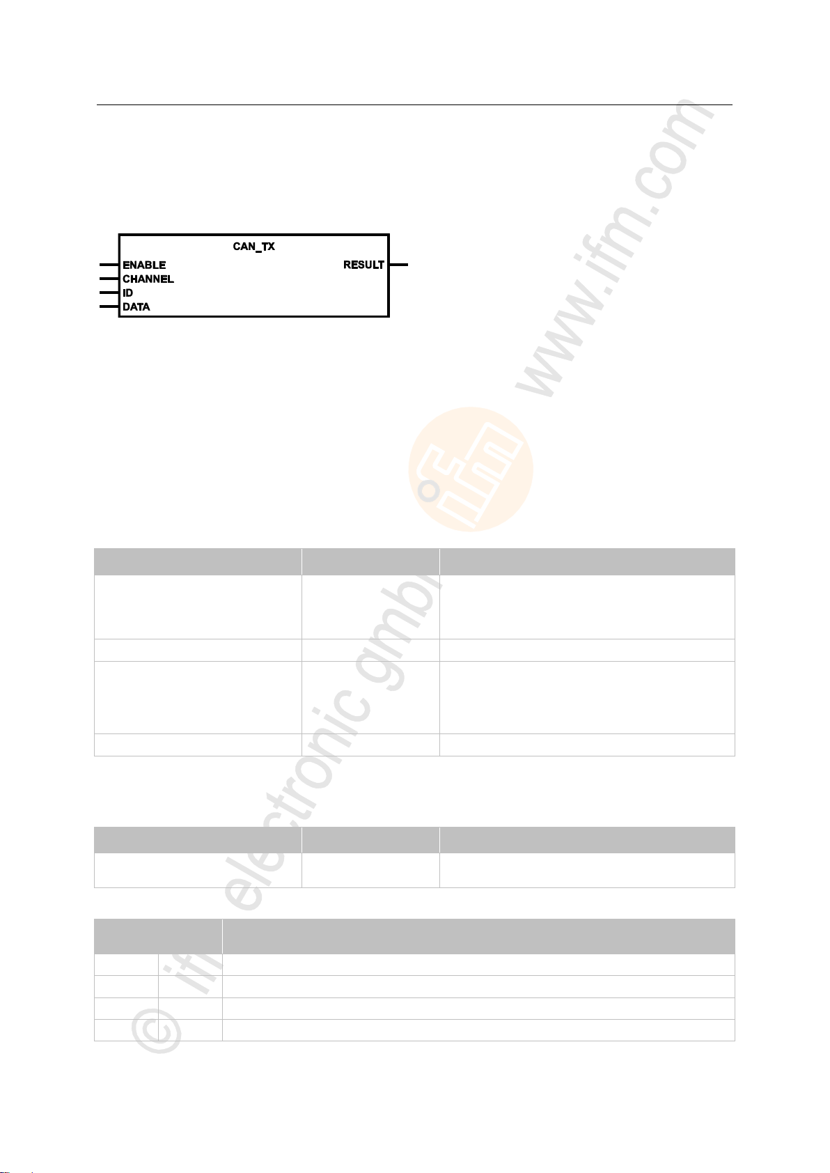
ifm Programming Manual BasicController relay CR0431 v03.03.00 05 / 2018
ifm function elements ifm function elements for the device CR0431
CAN_TX
Parameter
Data type
Description
ENABLE
BOOL
TRUE: execute this function element
FALSE: unit is not executed
> Function block inputs are not active
> Function block outputs are not specified
CHANNEL
BYTE
CAN interface (1...n) depending on the device
ID
DWORD
Number of the data object identifier:
normal frame (2 048 IDs):
0...2 047 = 0x0000 0000...0x0000 07FF
extended Frame (536 868 864 IDs):
2 048...536 870 911 = 0x0000 0800...0x1FFF FFFF
DATA
ARRAY [0..7] OF BYTE
data to be sent (1...8 bytes)
Parameter
Data type
Description
RESULT
BYTE
feedback of the function block
(possible messages → following table)
Value
dec | hex
Description
0
00
FB is inactive
1
01
function block execution completed without error
242
F2
Error: setting is not possible
250
FA
Error: FiFo is full – data was lost
Unit type = function block (FB)
Unit is contained in the library ifm_RawCAN_NT_Vxxyyzz.LIB
Symbol in CODESYS:
7522
>
Description
7523
CAN_TX sends a standard message per cycle.
The FB limits itself to a few functions and the required memory space is low.
> If an instance of this FB is called several times during a cycle, the data is also sent several times.
In case of the simple functions CAN_TX and CAN_RX, it is determined by means of the ID whether a
standard or an extended frame is to be sent. With the enhanced versions this is set via the input
EXTENDED. Therefore, extended frames in the ID area 0...2047 cannot be sent via the easy
functions.
>
Parameters of the inputs
7524
>
Parameters of the outputs
Possible results for RESULT:
77
7527
Page 78
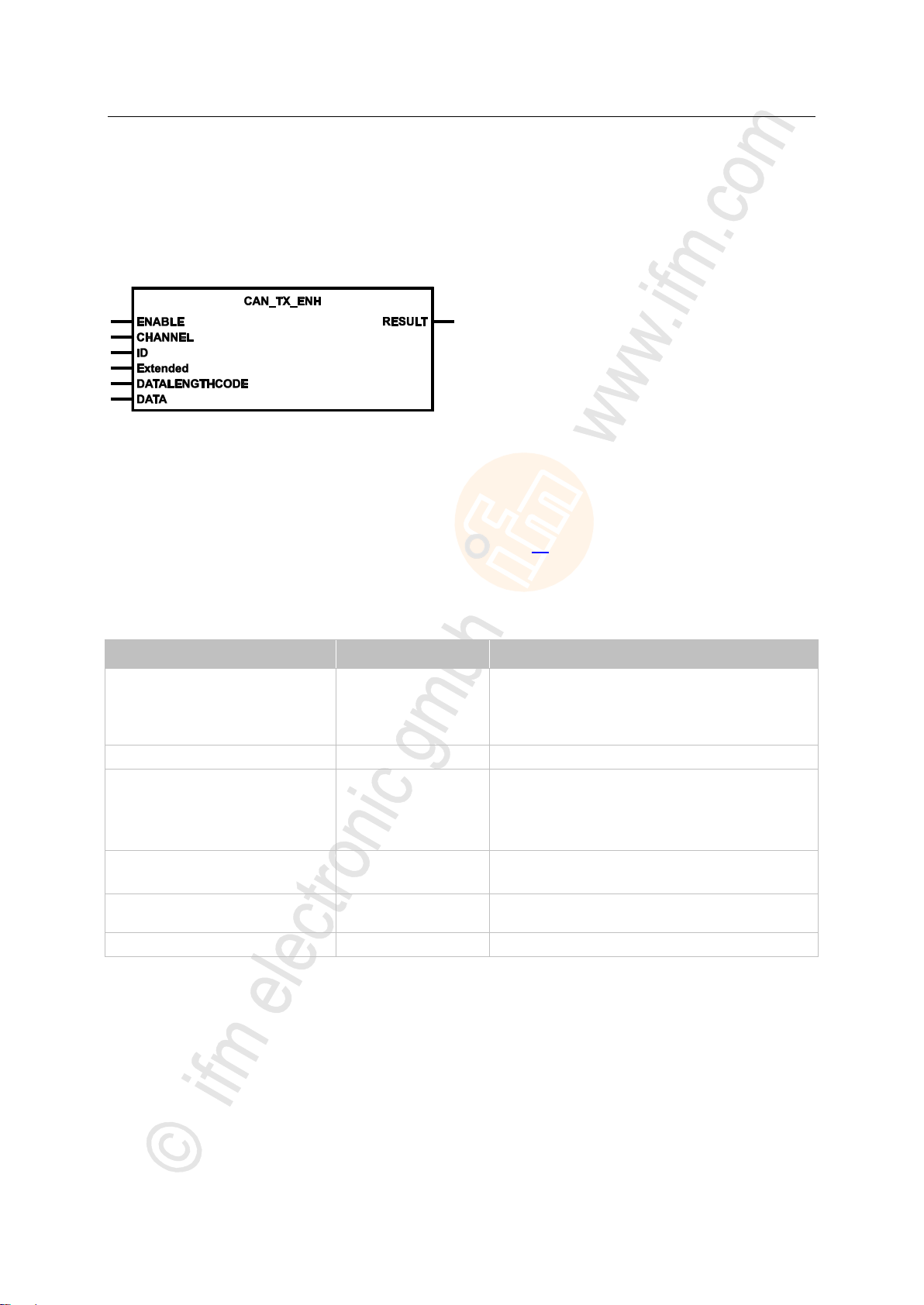
ifm Programming Manual BasicController relay CR0431 v03.03.00 05 / 2018
ifm function elements ifm function elements for the device CR0431
CAN_TX_ENH
Parameter
Data type
Description
ENABLE
BOOL := FALSE
TRUE: execute this function element
Edge: enter the new values
FALSE: unit is not executed
reset internal remote values
CHANNEL
BYTE
CAN interface (1...n) depending on the device
ID
DWORD
Number of the data object identifier:
normal frame (211 IDs):
0...2 047 = 0x0000 0000...0x0000 07FF
extended Frame (229 IDs):
0...536 870 911 = 0x0000 0000...0x1FFF FFFF
Extended
(optional use of the parameter)
BOOL := FALSE
TRUE: extended Frame (ID = 0...229-1)
FALSE: normal Frame (ID = 0...211-1)
DATALENGTHCODE
BYTE
= Data Length Code
number of the data bytes to be sent (0...8)
DATA
ARRAY [0..7] OF BYTE
data to be sent (1...8 bytes)
= CAN TX enhanced
Unit type = function block (FB)
Unit is contained in the library ifm_RawCAN_NT_Vxxyyzz.LIB
Symbol in CODESYS:
7558
>
Description
7559
Additional setting options are offered through CAN_TX_ENH (for: enhanced). Here, all CAN specific
characteristics can be set individually, e.g.:
Is it an 11 or a 29 bit identifier?
The additional inputs can be preset so that CAN_TX (→ p. 77) is not required.
> If an instance of this FB is called several times during a cycle, the data is also sent several times.
>
Parameters of the inputs
7634
78
Page 79

ifm Programming Manual BasicController relay CR0431 v03.03.00 05 / 2018
ifm function elements ifm function elements for the device CR0431
>
Parameter
Data type
Description
RESULT
BYTE
feedback of the function block
(possible messages → following table)
Value
dec | hex
Description
0
00
FB is inactive
1
01
function block execution completed without error
242
F2
Error: setting is not possible
250
FA
Error: FiFo is full – data was lost
Parameters of the outputs
Possible results for RESULT:
7527
79
Page 80
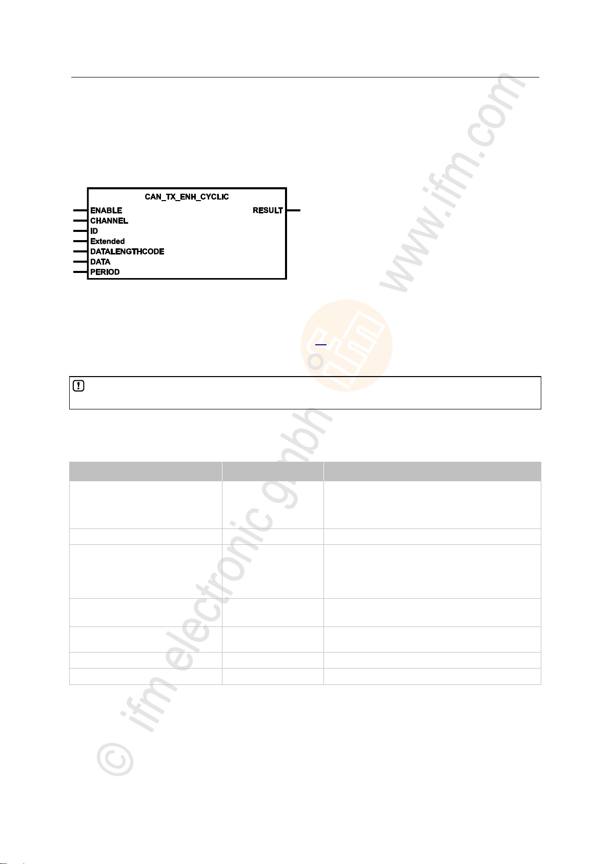
ifm Programming Manual BasicController relay CR0431 v03.03.00 05 / 2018
ifm function elements ifm function elements for the device CR0431
CAN_TX_ENH_CYCLIC
If a period is too short, this could lead to a high bus load which could affect the performance of the
complete system.
Parameter
Data type
Description
ENABLE
BOOL
TRUE: execute this function element
FALSE: unit is not executed
> Function block inputs are not active
> Function block outputs are not specified
CHANNEL
BYTE
CAN interface (1...n) depending on the device
ID
DWORD
Number of the data object identifier:
normal frame (211 IDs):
0...2 047 = 0x0000 0000...0x0000 07FF
extended Frame (229 IDs):
0...536 870 911 = 0x0000 0000...0x1FFF FFFF
Extended
(optional use of the parameter)
BOOL := FALSE
TRUE: extended Frame (ID = 0...229-1)
FALSE: normal Frame (ID = 0...211-1)
DataLengthCode
(optional use of the parameter)
BYTE := 8
length of the data to be sent (0...8 bytes)
DATA
ARRAY [0..7] OF BYTE
data to be sent (1...8 bytes)
PERIOD
TIME
period duration
= CAN TX enhanced cyclic
Unit type = function block (FB)
Unit is contained in the library ifm_RawCAN_NT_Vxxyyzz.LIB
Symbol in CODESYS:
7568
>
Description
CAN_TX_ENH_CYCLIC serves for cyclical transmitting of CAN messages.
Otherwise, the FB corresponds to CAN_TX_ENH (→ p. 78).
► Set the period duration via the parameter PERIOD.
>
Parameters of the inputs
7569
7582
80
Page 81

ifm Programming Manual BasicController relay CR0431 v03.03.00 05 / 2018
ifm function elements ifm function elements for the device CR0431
>
Parameter
Data type
Description
RESULT
BYTE
feedback of the function block
(possible messages → following table)
Value
dec | hex
Description
0
00
FB is inactive
1
01
FB execution completed without error – data is valid
8
08
function block is active
9
09
CAN is not active
242
F2
Error: setting is not possible
250
FA
Error: FiFo is full – data was lost
Parameters of the outputs
Possible results for RESULT:
7510
81
Page 82

ifm Programming Manual BasicController relay CR0431 v03.03.00 05 / 2018
ifm function elements ifm function elements for the device CR0431
Function elements: RAW-CAN remote
CAN_REMOTE_REQUEST ...................................................................................................................83
CAN_REMOTE_RESPONSE.................................................................................................................84
15057
82
Page 83
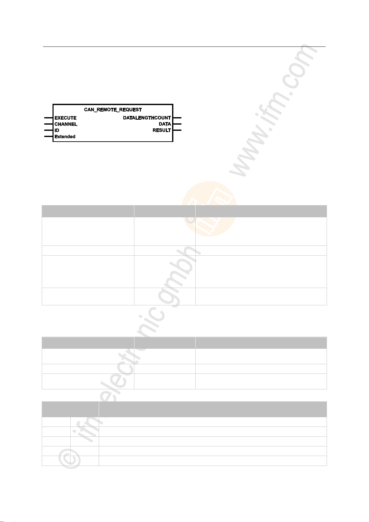
ifm Programming Manual BasicController relay CR0431 v03.03.00 05 / 2018
ifm function elements ifm function elements for the device CR0431
CAN_REMOTE_REQUEST
Parameter
Data type
Description
EXECUTE
BOOL := FALSE
FALSE TRUE (edge):
execute function element once
otherwise: function element is not active
A function element already started is processed.
CHANNEL
BYTE
CAN interface (1...n) depending on the device
ID
DWORD
Number of the data object identifier:
normal frame (211 IDs):
0...2 047 = 0x0000 0000...0x0000 07FF
extended Frame (229 IDs):
0...536 870 911 = 0x0000 0000...0x1FFF FFFF
Extended
(optional use of the parameter)
BOOL := FALSE
TRUE: extended Frame (ID = 0...229-1)
FALSE: normal Frame (ID = 0...211-1)
Parameter
Data type
Description
DATALENGTHCOUNT
BYTE
= Data Length Count
number of the data bytes received
DATA
ARRAY [0..7] OF BYTE
received data, (1...8 bytes)
RESULT
BYTE
feedback of the function block
(possible messages → following table)
Value
dec | hex
Description
0
00
FB is inactive
1
01
function block execution completed without error
5
05
FB is being processed – still receiving
9
09
CAN is not active
242
F2
Error: setting is not possible
Unit type = function block (FB)
Unit is contained in the library ifm_RawCAN_NT_Vxxyyzz.LIB
Symbol in CODESYS:
7625
>
Description
In order to request a remote message, an according requirement is dispatched via
CAN_REMOTE_REQUEST and the response of the other device is sent back as result.
>
Parameters of the inputs
>
7627
7628
Parameters of the outputs
Possible results for RESULT:
83
7629
Page 84

ifm Programming Manual BasicController relay CR0431 v03.03.00 05 / 2018
ifm function elements ifm function elements for the device CR0431
CAN_REMOTE_RESPONSE
BasicController: CR040n, CR041n, CR043n
BasicDisplay: CR045n
max. 40 remote messages
PDM360 NG: CR108n, CR120n
max. 100 remote messages
Parameter
Data type
Description
ENABLE
BOOL := FALSE
TRUE: execute this function element
Edge: enter the new values
FALSE: unit is not executed
reset internal remote values
CHANNEL
BYTE
CAN interface (1...n) depending on the device
ID
DWORD
Number of the data object identifier:
normal frame (211 IDs):
0...2 047 = 0x0000 0000...0x0000 07FF
extended Frame (229 IDs):
0...536 870 911 = 0x0000 0000...0x1FFF FFFF
Extended
(optional use of the parameter)
BOOL := FALSE
TRUE: extended Frame (ID = 0...229-1)
FALSE: normal Frame (ID = 0...211-1)
DATALENGTHCODE
BYTE
= Data Length Code
number of the data bytes to be sent (0...8)
DATA
ARRAY [0..7] OF BYTE
data to be sent (1...8 bytes)
Unit type = function block (FB)
Unit is contained in the library ifm_RawCAN_NT_Vxxyyzz.LIB
Symbol in CODESYS:
7631
>
Description
7633
CAN_REMOTE_RESPONSE provides data to the CAN controller in the device which is automatically
sent upon the request of a remote message.
This FB strongly depends on the device type. Only a limited number of remote messages can be set
up:
>
Parameters of the inputs
7634
84
Page 85

ifm Programming Manual BasicController relay CR0431 v03.03.00 05 / 2018
ifm function elements ifm function elements for the device CR0431
>
Parameter
Data type
Description
RESULT
BYTE
feedback of the function block
(possible messages → following table)
Value
dec | hex
Description
0
00
FB is inactive
6
06
FB is being processed – remote for ID not active
7
07
FB is being processed – remote for ID active
8
08
function block is active
10
0A
no further remote entrys available
242
F2
Error: setting is not possible
Parameters of the outputs
Possible results for RESULT:
7636
85
Page 86

ifm Programming Manual BasicController relay CR0431 v03.03.00 05 / 2018
ifm function elements ifm function elements for the device CR0431
5.2.3 Function elements: CANopen
Function elements: CANopen status ......................................................................................................86
Function elements: CANopen network management .............................................................................95
Function elements: CANopen object directory .......................................................................................99
Function elements: CANopen SDOs ....................................................................................................104
Function elements: CANopen SYNC ...................................................................................................117
Function elements: CANopen guarding ...............................................................................................121
Function elements: CANopen emergency ............................................................................................125
CANOPEN_ENABLE ..............................................................................................................................87
CANOPEN_GETBUFFERFLAGS ..........................................................................................................89
CANOPEN_GETSTATE .........................................................................................................................91
CANOPEN_SETSTATE .........................................................................................................................93
For CANopen, ifm electronic provides a number of function elements which will be explained in the
following.
Function elements: CANopen status
15059
15061
86
Page 87

ifm Programming Manual BasicController relay CR0431 v03.03.00 05 / 2018
ifm function elements ifm function elements for the device CR0431
CANOPEN_ENABLE
To avoid guarding or heartbeat errors the nodes must be "shut down" via an appropriate sequence
first.
Parameter
Data type
Description
ENABLE
BOOL := TRUE
TRUE:
• Enable CANopen for the selected channel
• Start CANopen manager or CANopen device
according to the configuration settings
FALSE:
• Disable CANopen for the selected channel
• Terminate CANopen manager or CANopen device
CHANNEL
BYTE
CAN interface (1...n) depending on the device
Baud rate
(optional use of the parameter)
WORD := 0
Baud rate [kbits/s]
permissible values = 20, 50, 100, 125, 250, 500, 800, 1 000
0 = use setting from the PLC configuration
Unit type = function block (FB)
Unit is contained in the library ifm_CANopen_NT_Vxxyyzz.LIB
Symbol in CODESYS:
7785
>
Description
CANOPEN_ENABLE allows to switch the CANopen master on or off.
► In the application program always call an own instance of the FB CANOPEN_ENABLE (→ p. 87)
for every CAN interface!
If the master is restarted after a stop, all other connected nodes also have to be re-initialised.
Without CANOPEN_ENABLE, the CANopen master is started automatically, as far as this has been
selected in the configuration.
The configured baud rate is only adopted if CAN_ENABLE (→ p. 61) has not been activated before.
>
Parameters of the inputs
7787
7788
87
Page 88

ifm Programming Manual BasicController relay CR0431 v03.03.00 05 / 2018
ifm function elements ifm function elements for the device CR0431
>
Parameters
Data type
Description
RESULT
BYTE
feedback of the function block
(possible messages → following table)
Value
dec | hex
Description
0
00
FB is inactive
1
01
function block execution completed without error
14
0E
FB is active
CANopen manager configures devices and sends SDOs
15
0F
FB is active
CANopen manager is started
238
EE
Error: CANopen configuration is too large and cannot be started
239
EF
Error: CANopen manager could not be started
242
F2
Error: setting is not possible
Parameters of the outputs
Possible results for RESULT:
7789
88
Page 89
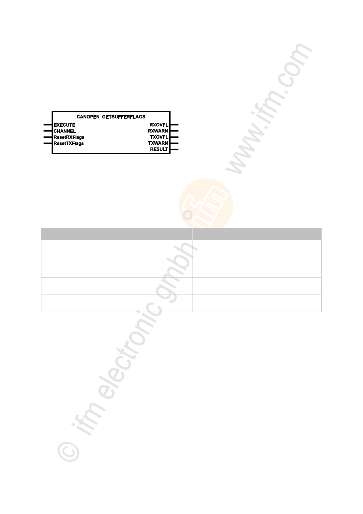
ifm Programming Manual BasicController relay CR0431 v03.03.00 05 / 2018
ifm function elements ifm function elements for the device CR0431
CANOPEN_GETBUFFERFLAGS
Parameter
Data type
Description
EXECUTE
BOOL := FALSE
FALSE TRUE (edge):
execute function element once
otherwise: function element is not active
A function element already started is processed.
CHANNEL
BYTE
CAN interface (1...n) depending on the device
ResetRXFlags
(optional use of the parameter)
BOOL := FALSE
TRUE: Provide fag status at the output and then reset
FALSE: function element is not executed
ResetTXFlags
(optional use of the parameter)
BOOL := FALSE
TRUE: Provide flag status at the output and then reset
FALSE: function element is not executed
= Get buffer flags
Unit type = function block (FB)
Unit is contained in the library ifm_CANopen_NT_Vxxyyzz.LIB
Symbol in CODESYS:
7890
>
Description
CANOPEN_GETBUFFERFLAGS supplies information on the buffer flags.
The flags can be reset via the optional inputs.
The function block returns the state of the overflow flags.
>
Parameters of the inputs
7892
7893
89
Page 90

ifm Programming Manual BasicController relay CR0431 v03.03.00 05 / 2018
ifm function elements ifm function elements for the device CR0431
>
Parameter
Data type
Description
RXOVFL
BOOL
condition of the RX overflow flag
TRUE: overflow in the receive buffer
FALSE: no overflow in receive buffer
RXWARN
BOOL
condition of the RX overflow warning flag
TRUE: level in the receive buffer is critical
FALSE: level in the input buffer is uncritical
TXOVFL
BOOL
condition of the TX overflow flag
TRUE: overflow in the transmit buffer
FALSE: no overflow in transmit buffer
TXWARN
BOOL
Condition of the TX overflow warning flag
TRUE: Level in the transmit buffer is critical
FALSE: Level in the transmit buffer is uncritical
RESULT
BYTE
feedback of the function block
(possible messages → following table)
Value
dec | hex
Description
0
00
FB is inactive
1
01
function block execution completed without error
8
08
function block not yet executed
242
F2
Error: setting is not possible
Parameters of the outputs
Possible results for RESULT:
7894
90
Page 91
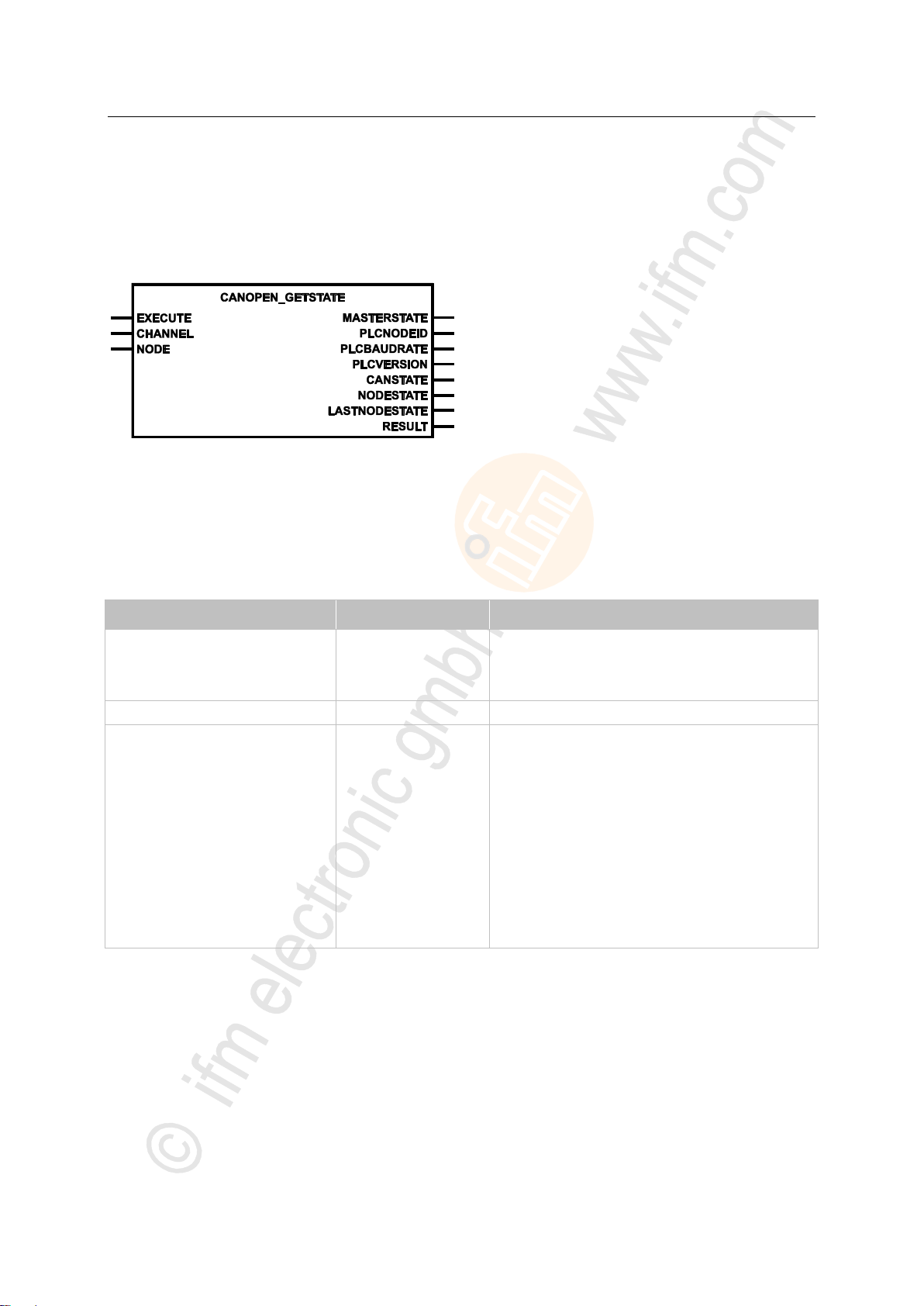
ifm Programming Manual BasicController relay CR0431 v03.03.00 05 / 2018
ifm function elements ifm function elements for the device CR0431
CANOPEN_GETSTATE
Parameter
Data type
Description
EXECUTE
BOOL := FALSE
FALSE TRUE (edge):
execute function element once
otherwise: function element is not active
A function element already started is processed.
CHANNEL
BYTE
CAN interface (1...n) depending on the device
NODE
BYTE
Node ID = ID of the node (0...127)
Device as CANopen master:
Value = 0:
Only the status information of the device itself is returned at the
outputs. The outputs with information on the nodes are invalid.
Value not 0:
Node ID of a node in the network. For this one as well as for the
device the states are returned at the outputs.
Device as CANopen slave:
Value = 0 (preset):
The status information of the slave is returned at the outputs.
Value not 0:
no action
= Get state
Unit type = function block (FB)
Unit is contained in the library ifm_CANopen_NT_Vxxyyzz.LIB
Symbol in CODESYS:
7865
>
Description
Via CANOPEN_GETSTATE, parameters of the master, a slave device or a specific node in the
network can be set.
>
Parameters of the inputs
7867
7868
91
Page 92

ifm Programming Manual BasicController relay CR0431 v03.03.00 05 / 2018
ifm function elements ifm function elements for the device CR0431
>
Parameter
Data type
Description
MASTERSTATE
BYTE
Master state = internal state of the master:
0 = 0x00 = master starts up
4 = 0x04 = node configuration running
5 = 0x05 = normal operating state of the master
255 = 0xFF = PLC running as slave
PLCNODEID
BYTE
PLC node ID = node ID of the PLC the program is running on
Value = 0...127 = 0x00...0x7F
PLCBAUDRATE
DWORD
Baudrate of the PLC
PLCVERSION
DWORD
PLC version
CANSTATE
BYTE
Status of the CANopen network
Device operated as master:
Node ID = 0 (device as such):
0 = 0x00 = OK
128 = 0x80 = BUSOFF
Node ID ≠ 0 (node):
0 = 0x00 = OK
1 = 0x01 = guard or heartbeat error on node
128 = 0x80 = BUSOFF
Device operated as slave:
0 = 0x00 = OK
1 = 0x01 = guard or heartbeat error
128 = 0x80 = BUSOFF
NODESTATE
BYTE
Node state = internal node state of a slave seen from the master's
perspective. The input NODEID identifies the node.
-1 = 0xFF = reset after ResetNode
1 = 0x01 = waiting for BOOTUP
2 = 0x02 = after receipt of the BOOTUP message
3 = 0x03 = not yet configured: STOPPED
4 = 0x04 = after configuration with SDOs: PRE-OPERATIONAL
5 = 0x05 = after starting the node: OPERATIONAL
97 = 0x61 = optional node
98 = 0x62 = other device type configured than in 0x1000
99 = 0x63 = node guarding
LASTNODESTATE
BYTE
Last Node State
Node state according to CANopen (with these values the status is also
coded in the corresponding messages with regard to the node).
0
0x00
BOOTUP
4
0x04
STOPPED
5
0x05
OPERATIONAL
127
0x7F
PRE-OPERATIONAL
RESULT
BYTE
feedback of the function block
(possible messages → following table)
Value
dec | hex
Description
0
00
FB is inactive
1
01
FB execution completed without error – data is valid
8
08
FB is active – not yet processed
242
F2
Error: setting is not possible
Parameters of the outputs
7869
Possible results for RESULT:
92
Page 93

ifm Programming Manual BasicController relay CR0431 v03.03.00 05 / 2018
ifm function elements ifm function elements for the device CR0431
CANOPEN_SETSTATE
Parameter
Data type
Description
EXECUTE
BOOL := FALSE
FALSE TRUE (edge):
execute function element once
otherwise: function element is not active
A function element already started is processed.
CHANNEL
BYTE
CAN interface (1...n) depending on the device
NODE
BYTE
Node ID = ID of the node (0...127)
Device as CANopen master:
Value = 0:
The changes only refer to the device itself.
Value not 0:
Node ID of a node in the network the parameters of which are to be
changed. The established settings are only adopted for this node (not
for the device).
Device as CANopen slave:
In slave mode, the node ID of the slave can be set via this input.
Value = 0:
no action
Value not 0:
The function block adopts this value as the new node ID of the device.
GlobalStart
(optional use of the parameter)
BOOL := TRUE
Requirement: FB must be called immediately after starting the IEC
program. This setting overwrites the setting of the configuration.
TRUE: Start all participants simultaneously
FALSE: Start all participants one after the other
CfgTimeout
(optional use of the parameter)
TIME := T#0ms
set configuration timeout for a node:
Value = 0:
no action – retain configuration data
Value not 0:
overwrite data from the configuration with the new value
= Set state
Unit type = function block (FB)
Unit is contained in the library ifm_CANopen_NT_Vxxyyzz.LIB
Symbol in CODESYS:
7858
>
Description
7860
Via CANOPEN_SETSTATE, parameters of the master, a slave device or a node in the network can be
set.
The treatment of the NMT state of master, node or device is carried out in the CAN stack or via the
commands of the FB CANOPEN_NMTSERVICES (→ p. 97). At the same time admissibility checks are
carried out. For reasons of consistency no inputs are provided for this purpose.
>
Parameters of the inputs
7861
93
Page 94

ifm Programming Manual BasicController relay CR0431 v03.03.00 05 / 2018
ifm function elements ifm function elements for the device CR0431
Parameter
Data type
Description
InitNoSdos
(optional use of the parameter)
BOOL := FALSE
To the node indicated in NODE, during initialisation,...
TRUE: do not send configuration data
FALSE: send configured SDOs
Parameter
Data type
Description
RESULT
BYTE
feedback of the function block
(possible messages → following table)
Value
dec | hex
Description
0
00
FB is inactive
1
01
FB execution completed without error – data is valid
8
08
FB is active – not yet processed
242
F2
Error: setting is not possible
>
Parameters of the outputs
Possible results for RESULT:
7862
94
Page 95

ifm Programming Manual BasicController relay CR0431 v03.03.00 05 / 2018
ifm function elements ifm function elements for the device CR0431
Function elements: CANopen network management
CANOPEN_GETNMTSTATESLAVE .....................................................................................................96
CANOPEN_NMTSERVICES ..................................................................................................................97
15063
95
Page 96

ifm Programming Manual BasicController relay CR0431 v03.03.00 05 / 2018
ifm function elements ifm function elements for the device CR0431
CANOPEN_GETNMTSTATESLAVE
Parameter
Data type
Description
EXECUTE
BOOL := FALSE
FALSE TRUE (edge):
execute function element once
otherwise: function element is not active
A function element already started is processed.
CHANNEL
BYTE
CAN interface (1...n) depending on the device
Parameter
Data type
Description
NMTSTATE
BYTE
Network operating status of the node
0 = INIT
1 = OPERATIONAL
2 = PRE-OPERATIONAL
3 = STOPPED
RESULT
BYTE
feedback of the function block
(possible messages → following table)
Value
dec | hex
Description
0
00
FB is inactive
1
01
function block execution completed without error
8
08
FB is active – not yet processed
242
F2
Error: setting is not possible
= Get network management state slave
Unit type = function block (FB)
Unit is contained in the library ifm_CANopen_NT_Vxxyyzz.LIB
Symbol in CODESYS:
7851
>
Description
► Only use the FB if the device is operated as CANopen slave!
With CANOPEN_GETNMTSTATESLAVE, only the operating state according to CANopen and an
error message are reported to the application if an invalid state transition has been requested.
>
Parameters of the inputs
>
Parameters of the outputs
7853
7854
7855
Possible results for RESULT:
96
Page 97

ifm Programming Manual BasicController relay CR0431 v03.03.00 05 / 2018
ifm function elements ifm function elements for the device CR0431
CANOPEN_NMTSERVICES
Parameter
Data type
Description
EXECUTE
BOOL := FALSE
FALSE TRUE (edge):
execute function element once
otherwise: function element is not active
A function element already started is processed.
CHANNEL
BYTE
CAN interface (1...n) depending on the device
NODE
BYTE
CANopen ID of the node
permissible = 0...127 = 0x00...0x7F
NODE = 0:
command applies to all nodes in the network
NODE = Node ID of the device:
command applies to the device as such
NMTSERVICE
BYTE
network command
0 = init node (except master)
1 = enter PRE-OPERATIONAL
2 = start node
3 = reset node
4 = reset communication
5 = stop node
Timeout
(optional use of the parameter)
TIME := T#0ms
waiting time of the FB for the initialisation
when the time has elapsed, the FB stops waiting.
0 = use value from the configuration
= Network management services
Unit type = function block (FB)
Unit is contained in the library ifm_CANopen_NT_Vxxyyzz.LIB
Symbol in CODESYS:
7843
>
Description
Depending on its NMT command entries, CANOPEN_NMTSERVICES either triggers an NMT
command or the initialisation of a node.
NMT = Network-ManagemenT
The function block updates the internal node status. If a state transition to CANopen (→ system
manual "Know-How ecomatmobile" > NMT state) should not be permitted, the command is not
executed.
A CANopen device can automatically change its CANopen state by means of the FB:
preoperational operational
>
Parameters of the inputs
7844
7847
97
Page 98

ifm Programming Manual BasicController relay CR0431 v03.03.00 05 / 2018
ifm function elements ifm function elements for the device CR0431
>
Parameter
Data type
Description
RESULT
BYTE
feedback of the function block
(possible messages → following table)
Value
dec | hex
Description
0
00
FB is inactive
1
01
function block execution completed without error
8
08
function block is active
35
23
at least 1 SDO of the configuration was not successful
36
24
node was already initialised
37
25
when initialisation was requested the node was not in the PRE-OPERATIONAL mode
43
2B
master / slave is not initialised
241
F1
Error: CANopen state transition is not permitted
242
F2
Error: setting is not possible
Parameters of the outputs
Possible results for RESULT:
7848
98
Page 99

ifm Programming Manual BasicController relay CR0431 v03.03.00 05 / 2018
ifm function elements ifm function elements for the device CR0431
Function elements: CANopen object directory
CANOPEN_GETODCHANGEDFLAG .................................................................................................100
CANOPEN_READOBJECTDICT .........................................................................................................101
CANOPEN_WRITEOBJECTDICT .......................................................................................................102
15065
99
Page 100

ifm Programming Manual BasicController relay CR0431 v03.03.00 05 / 2018
ifm function elements ifm function elements for the device CR0431
CANOPEN_GETODCHANGEDFLAG
Parameter
Data type
Description
EXECUTE
BOOL := FALSE
FALSE TRUE (edge):
execute function element once
otherwise: function element is not active
A function element already started is processed.
CHANNEL
BYTE
CAN interface (1...n) depending on the device
IDX
WORD
index in object directory
SUBIDX
BYTE
sub-index referred to the index in the object directory
Parameter
Data type
Description
DATA
DWORD
parameter value
RESULT
BYTE
feedback of the function block
(possible messages → following table)
Value
dec | hex
Description
0
00
FB is inactive
1
01
function block execution completed without error
8
08
FB is active – not yet processed
242
F2
Error: setting is not possible
= Get object directory changed flag
Unit type = function block (FB)
Unit is contained in the library ifm_CANopen_NT_Vxxyyzz.LIB
Symbol in CODESYS:
7927
>
Description
CANOPEN_GETODCHANGEDFLAG reports any change of value for a particular object directory
entry.
>
Parameters of the inputs
>
Parameters of the outputs
7928
7930
7931
Possible results for RESULT:
100
 Loading...