

Page 1

Montage- und
Installationshinweise
Mounting and installation
instructions
Mobilsteuerung
CabinetController R 360
CR0302
DEUTSCHENGLISH
Sachnr. 7390430 /00 11 / 2014
R
Page 2

CABINETCONTROLLER CR0302
SEITE 2
Sicherheitshinweise
Diese Beschreibung ist Bestandteil des Gerätes. Sie enthält Texte
und Abbildungen zum korrekten Umgang mit dem Modul und
muss vor einer Installation oder dem Einsatz gelesen werden.
Befolgen Sie die Angaben der Beschreibung. Nichtbeachten der Hinweise,
Betrieb außerhalb der nachstehend bestimmungsgemässen Verwendung,
falsche Installation oder fehlerhafte Handhabung können schwerwiegende
Beeinträchtigungen der Sicherheit von Menschen und Anlagen zur Folge
haben.
Die Anleitung richtet sich an Personen, die im Sinne der EMV- und der Niederspannungs-Richtlinie als “fachkundig” angesehen werden können. Die Steuerungen sind von einer Elektrofachkraft (Programmierer bzw. Servicetechniker)
einzubauen und in Betrieb zu setzen.
Wenn das Gerät nicht vom mobilen Bordnetz (12/24 V Batteriebetrieb) versorgt wird, ist darauf zu achten, dass die externe Spannung gemäß den Kriterien für sichere Kleinspannung (SELV) erzeugt und zugeführt wird, da diese
ohne weitere Maßnahmen zur Versorgung der angeschlossenen Steuerung,
der Sensorik und der Aktorik zur Verfügung gestellt wird.
Die Verdrahtung aller in Zusammenhang mit dem SELV-Kreis des Geräts stehenden Signale muss ebenfalls den SELV-Kriterien entsprechen (sichere
Schutzkleinspannung, galvanisch sicher getrennt von anderen Stromkreisen).
Wird die zugeführte SELV-Spannung extern geerdet (SELV wird zu PELV), so
geschieht dies in der Verantwortung des Betreibers und im Rahmen der dort
geltenden nationalen Installations-Vorschriften. Alle Aussagen in dieser Bedienungsanleitung beziehen sich auf das bezügl. der SELV-Spannung nicht geerdete Gerät.
An den Anschlussklemmen dürfen nur die in den technischen Daten, bzw. auf
dem Geräteaufdruck angegebenen Signale eingespeist bzw. die zugelassenen
Zubehörkomponenten der ifm electronic gmbh angeschlossen werden.
Das Gerät ist gemäß nachstehender technischer Spezifikation in einem weiten
Umgebungs-Temperaturbereich betreibbar. Aufgrund der zusätzlichen Eigenerwärmung kann es an den Gehäuse-Wandungen beim Berühren in heißer
Umgebung zu hohen wahrnehmbaren Temperaturen kommen.
Bei Fehlfunktionen oder Unklarheiten setzen Sie sich bitte mit dem Hersteller
in Verbindung. Eingriffe in das Gerät können schwerwiegende Beeinträchtigungen der Sicherheit von Menschen und Anlagen zur Folge haben. Sie sind
nicht zulässig und führen zu Haftungs- und Gewährleistungsausschluss.
Page 3
Inhalt
1. Bestimmungsgemäße Verwendung / Funktion Seite 3
2. Programmierung Seite 3
3. Montage Seite 4
4. Elektrischer Anschluss Seite 4
5. Wartung, Instandsetzung und Entsorgung Seite 4
6. Zulassungen/Normen Seite 4
Technische Daten (Datenblätter 1...5)
Maße, Mechanik, Elektronik Seite 5
Betriebszustände (Status-LED) Seite 6
Prüfnormen und Bestimmungen Seite 6
Kennwerte der Ein-/Ausgänge Seite 7
Anschlussbelegung Seite 9
1. Bestimmungsgemäße Verwendung / Funktion
Die freiprogrammierbaren Steuerungen der Baureihe „CabinetController R 360“
sind für den Einsatz unter erschwerten Bedingungen ausgelegt (z.B. erweiterter
Temperaturbereich, starke Vibrationen, intensive EMV-Belastung).
Sie sind geeignet zum direkten Einbau in Maschinen im mobilen und robusten
Einsatz. Die Ein- und Ausgänge sind durch ihre Spezifikation speziell für diesen
Einsatz ausgelegt. Integrierte Hardware- und Software-Funktionen (Betriebssystem) bieten einen hohen Schutz für die Maschine.
Die Steuerungen können als CANopen-Master eingesetzt werden.
Die Steuerungen CabinetController R 360 sind nicht für sicherheitsrelevante
Aufgaben im Sinne des Personenschutzes zugelassen.
2. Programmierung
Die Applikationssoftware kann vom Anwender komfortabel mit dem IEC 61131-3
konformen Programmiersystem CODESYS erstellt werden.
Zur Programmierung der Steuerung wird neben dem Programmiersystem noch
das vollständige Systemhandbuch benötigt.
Sollte es nicht vorliegen, kann es kostenlos bei einer der rückseitigen ifm-Niederlassungen angefordert werden. Als Download-File (PDF-Format) steht das Systemhandbuch auch im Internet unter „www.ifm.com“ zur Verfügung.
➔ Systemhandbuch R360; deutsch (Bestell-Nr. EC2038)
➔ Datenblatt direkt ➔ CR0302 ➔ weitere Informationen
Für die sichere Funktion der vom Anwender erstellten Applikationsprogram-
me ist dieser selbst verantwortlich. Bei Bedarf muss er zusätzlich entsprechend der nationalen Vorschriften eine Abnahme durch entsprechende Prüf- und
Überwachungsorganisationen dürchführen lassen.
Internet
Anfrage
DEUTSCH
CABINETCONTROLLER CR0302
SEITE 3
Page 4
3. Montage
Die Steuerung ist für den Einbau in eine trockene, geschlossene Umgebung vorgesehen (z.B. Bedienkonsole des Führerstandes, separates Bediengehäuse, etc.).
Die Befestigung erfolgt mit 4 Schrauben M4 x L.
4. Elektrischer Anschluss
Zum Schutz des gesamten Systems (Verkabelung und Steuerung) sind die einzelnen Stromkreise abzusichern.
5. Wartung, Instandsetzung und Entsorgung
Da innerhalb der Steuerung keine vom Anwender zu wartenden Bauteile enthalten sind, darf das Gehäuse nicht geöffnet werden. Die Instandsetzung der Steuerung darf nur durch den Hersteller durchgeführt werden. Die Entsorgung muss
gemäß den nationalen Umweltvorschriften erfolgen.
6. Zulassungen/Normen
Prufnormen und Bestimmungen ➔ Technische Daten.
Die CE-Konformitatserklarung und die E1-Zulassung sind abrufbar unter:
➔ Datenblatt-Suche ➔ CR0302 ➔ Zulassungen
www.ifm.com
CABINETCONTROLLER CR0302
SEITE 4
Bezeichnung Potential Stecker : Pin-Nr. Sicherung
Versorgungsspannung U
B
X1:01 max. 2 A T
Versorgungsspannung Digital-Ausgänge U
COM01/02
X3:05/10 max. 16 A
U
COM03
X5:02
Page 5
DEUTSCH
CABINETCONTROLLER CR0302
SEITE 5
223
134
108
198
LED
Ø 4,5
X2 X4 X3
X5
X1
RS232
2
1
ifm electronic gmbh • Friedrichstraße 1 • 45128 Essen
05.11.2014
CR0302
Mobilsteuerung
CabinetController
24 Eingänge
12 Ausgänge
Programmierung
nach IEC 61131-3
Betriebsspannung
10...32 V DC
Technische Änderungen behalten wir uns ohne Ankündigung vor! CR0302 / Seite 1
Technische Daten Einsetzbar als CANopen-Master oder intelligentes E/A-Modul
24 Eingänge (8 analog/16 digital) und 12 Ausgänge (digital)
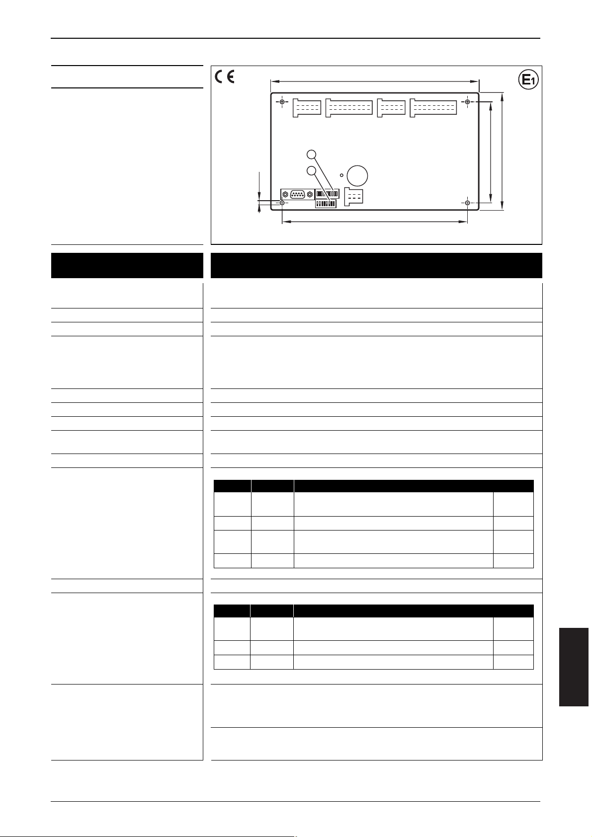
Aufbau offene Platine
(zum mechanischen Schutz in einer Vergusswanne vergossen)
Maße (L xBxH) 223 x 133 x 33 mm
Montage Befestigung über 4 Bohrungen (Ø 4,5 mm)
Anschlüsse AMP Crimpstecker, rüttelfest einrastbar, verpolsicher
(Kontakte AMP-Junior-Timer)
Ein-/Ausgänge 2 x 10-polig, 2 x 18-polig
Betriebsspannung und CAN-Bus 1 x 6-polig
Programmierung, TEST D-Sub-Buchse, 9-polig
Gewicht 0,49 kg
Umgebungstemperatur – 40...85 °C (lastabhängig)
Lagertemperatur – 40...85 °C
Schutzart IP 20
Eingänge 24
mögliche Konfigurationen
Ausgänge 12
mögliche Konfigurationen
Zubehör Bestell-Nr. EC2075
(gesondert zu bestellen) Steckersatz für CabinetController, bestehend aus:
AMP Crimp-Buchsengehäuse, 1 x 6-polig, 2 x 10-polig, 3 x 18-polig
inkl. Crimp-Kontakte (Junior Power Timer)
Bestell-Nr. EC2076
RS 232 Programmieradapter zur Beschaltung des TEST-Eingangs mit U
B
Anzahl Signal Ausführung
8 analog 0...10/32 V DC, 0...20 mA oder ratiometrisch A
oder digital als binärer Spannungseingang B
L
8 digital für positive Gebersignale, diagnosefähig B
L
4 digital für positive Gebersignale, diagnosefähig B
L
oder Frequenz Impulseingänge, max. 30 kHz I
L
4 digital für positive/negative Gebersignale B
L/H
Anzahl Signal Ausführung
4 digital plusschaltend (High-Side) B
H
oder PWM PWM-Frequenz, max. 250 Hz PWM
4 digital plusschaltend (High-Side) B
H
4 digital plusschaltend (High-Side) B
H
Abkürzungen
A = analog
B
H
= binär High-Side
B
L
= binär Low-Side
I
L
= Impuls Low-Side
PWM = Pulsweitenmodulation
1) LED-Leiste (10-stellig) 2) DIP-Schalter (8-stellig)
Page 6
CABINETCONTROLLER CR0302
SEITE 6
ifm electronic gmbh • Friedrichstraße 1 • 45128 Essen
05.11.2014Technische Änderungen behalten wir uns ohne Ankündigung vor! CR0302 / Seite 2
CR0302 Technische Daten
Betriebsspannung U
B
10...32 V DC
Überspannung 36 V für t ≤ 10 s
Unterspannungserkennung bei U
B
≤ 9,5 V
Auto-Save bei UB≤ 9,0 V
Stromaufnahme ≤ 100 mA (ohne externe Last bei 24 V DC)
externe Absicherung mit max. 10 A
CAN Schnittstelle CAN Interface 2.0 B, ISO 11898
Baudrate 50 kBit/s...1 MBit/s (Defaulteinstellung 125 kBit/s)
Kommunikationsprofil CANopen, CiA DS 301 Version 3.0, CiA DS 401 Version 1.4
Node-ID (CANopen) hex 20 (= dez 32)
Serielle Schnittstelle RS 232C
Baudrate 9,6 / 19,2 / 28,8 / 38,4 / 57,6 kBit/s (Default 57,6 kBit/s)
Topologie point-to-point (max. 2 Teilnehmer); Master-Slave-Verbindung
Protokoll Vordefiniertes ifm-Protokoll (INTELHEX)
Prozessor CMOS-Microcontroller 16 Bit C167C
Taktfrequenz 20 MHz
Speicher
Programmspeicher 192 kByte Flash
Datenspeicher 48 kByte SRAM, 32 kByte Flash, 4 kByte EEPROM
Datenspeicher (ausfallsicher) 256 Byte (Auto-Save-Speicher)
Anzeige-/Eingabeelemente 10-stellige LED-Leiste
(frei konfigurierbar) 8-stelliger DIP-Schalter
Status-Anzeige Zweifarben-LED (Rot/Grün)
Betriebszustände (Status-LED)
Prüfnormen und Bestimmungen
Klimatest Feuchte/Wärme nach EN 60068-2-30, Test Db
(≤ 95% rel. Luftfeuchtigkeit, nicht kondensierend)
Schutzartprüfung nach EN 60529
Mechanische Festigkeit Schwingen nach EN 60068-2-6, Test Fc
Schocken nach EN 60068-2-27, Test Ea
Schocken im Betrieb nach EN 60068-2-29, Test Eb
Störfestigkeit gegen nach ISO 7637-2: 2004, Impulse 2a, 3a, 3b, Schärfegrad 4, Funktionszustand A
leitungsgebundene Störungen nach ISO 7637-2: 2004, Impuls 5, Schärfegrad 1, Funktionszustand A
nach ISO 7637-2: 2004, Impuls 1, 2b, Schärfegrad 4, Funktionszustand C
Störfestigkeit gegen Fremdfeld gemäß UN/ECE-R10 mit 100 V/m (E1-Typgenehmigung)
und EN 61000-6-4 (CE)
Störabstrahlung gemäß UN/ECE-R10 (E1-Typgenehmigung)
und EN 61000-6-2 (CE)
LED-Farbe Zustand Beschreibung
– Aus keine Betriebsspannung
Orange 1 x Ein Initialisierung oder Reset Checks
Grün 5 Hz kein Betriebssystem geladen
Grün 2,0 Hz Run
Ein Stop
Rot 2,0 Hz Run mit Fehler
Ein Fatal Error oder Stop mit Fehler
Page 7

DEUTSCH
CABINETCONTROLLER CR0302
SEITE 7
CR0302 Kennwerte der Eingänge
Analog-Eingänge ■ Spannungseingänge
X2:01...10, A_IN 00...A_IN07 Eingangsspannung 0...10 V oder 0...32 V
konfigurierbar als... Auflösung 10 bit
Genauigkeit ± 1% FS
Eingangswiderstand 78,4 kΩ (0...10 V), 46,6 kΩ (0...32 V)
Eingangsfrequenz 50 Hz
■ Stromeingänge, diagnosefähig
Eingangsstrom 0...20 mA
Auflösung 10 bit
Genauigkeit ± 1% FS
Eingangswiderstand 400 Ω
Eingangsfrequenz 50 Hz
Bei Strömen > 23 mA wird das Kanalpaar auf Spannungseingang umgeschaltet!
■ Spannungseingänge, 0...32 V, ratiometrisch
Funktion (U
IN
÷ UB) x 1000 ‰
Wertebereich 0...1000 ‰
■ Binäre Spannungseingänge für positive Gebersignale
Die Konfiguration/Umschaltung der Analog-Eingänge A_IN 00...07 erfolgt paarweise!
Dabei sind folgende Eingänge zusammengefasst: 0+4, 1+5, 2+6, 3+7
Digital-Eingänge ■ Digitaleingänge für positive Gebersignale, diagnosefähig
X4:01...08, IN 00...IN07 Einschaltpegel > 0,6 U
B
konfigurierbar als... Ausschaltpegel < 0,3 U
B
Eingangswiderstand 3,21 kΩ
Eingangsfrequenz 50 Hz
Digital-Eingänge ■ Digitaleingänge für positive Gebersignale, diagnosefähig
X4:11...14, IN 08...IN11 Einschaltpegel > 0,6 U
B
konfigurierbar als... Ausschaltpegel < 0,3 U
B
Eingangswiderstand 3,16 kΩ
Eingangsfrequenz 50 Hz
■ Frequenzeingänge für positive Gebersignale, diagnosefähig
Einschaltpegel 0,4...0,7 U
B
Ausschaltpegel 0,2...0,24 U
B
Eingangswiderstand 3,16 kΩ
Messbereich 0...2 kHz oder 1...30 kHz
Digital-Eingänge ■ Digitaleingänge für positive Gebersignale
X4:15...18, IN 12...IN15 Einschaltpegel > 0,6 U
B
konfigurierbar als... Ausschaltpegel < 0,3 U
B
Eingangswiderstand 3,21 kΩ
Eingangsfrequenz 50 Hz
■ Digitaleingänge für negative Gebersignale
Einschaltpegel < 0,2 U
B
Ausschaltpegel > 0,5 U
B
Eingangswiderstand 3,21 kΩ
Eingangsfrequenz 50 Hz
Die Konfiguration/Umschaltung der Digital-Eingänge IN 12...15 erfolgt paarweise!
Dabei sind folgende Eingänge zusammengefasst: 12+13, 14+15
Test-Eingang Für die Dauer des Testbetriebes (z.B. zur Programmierung), muß der TEST-Eingang
RS 232, D-Sub-Stecker, Pin 09 mit U
B
(10...32 V DC) verbunden werden.
Für den „RUN“-Betrieb bleibt der TEST-Eingang unbeschaltet.
siehe auch Anschlussbelegung, Seite 5
ifm electronic gmbh • Friedrichstraße 1 • 45128 Essen
05.11.2014Technische Änderungen behalten wir uns ohne Ankündigung vor! CR0302 / Seite 3
Page 8

CABINETCONTROLLER CR0302
SEITE 8
CR0302 Kennwerte der Ausgänge
Digital-Ausgänge ■ Halbleiterausgänge, plusschaltend (High-Side), kurzschluss- und überlastfest
X3:01...04, OUT 00...OUT03 Schaltspannung 10...32 V DC
konfigurierbar als... Schaltstrom max. 2 A
■ PWM-Ausgänge
PWM-Frequenz max. 250 Hz
Einstellauflösung 0,1 %
Laststrom max. 2 A
Die Ausgänge 0...3 sind mit einem gemeinsamen U
COM
-Anschluss zusammengefasst.
Digital-Ausgänge ■ Halbleiterausgänge, plusschaltend (High-Side), kurzschluss- und überlastfest
X3:06...09, OUT 04...OUT07 Schaltspannung 10...32 V DC
Schaltstrom max. 2 A
Die Ausgänge 4...7 sind mit einem gemeinsamen U
COM
-Anschluss zusammengefasst.
Digital-Ausgänge ■ Halbleiterausgänge, plusschaltend (High-Side), kurzschluss- und überlastfest
X5:01...18, OUT 08...OUT11 Schaltspannung 10...32 V DC
Schaltstrom max. 2 A
Die Ausgänge 8...11 sind mit einem gemeinsamen U
COM
-Anschluss zusammengefasst.
Externe Freilaufdiode! Zum Schutz der Ausgänge müssen bei hohen Abschaltenergien (induktiven bzw.
kapazitiven Lasten) Freilaufdioden parallel zur Last geschaltet werden.
siehe auch Anschlussbelegung, Seite 5
ifm electronic gmbh • Friedrichstraße 1 • 45128 Essen
05.11.2014Technische Änderungen behalten wir uns ohne Ankündigung vor! CR0302 / Seite 4
Page 9

DEUTSCH
CABINETCONTROLLER CR0302
SEITE 9
ifm electronic gmbh • Friedrichstraße 1 • 45128 Essen
05.11.2014Technische Änderungen behalten wir uns ohne Ankündigung vor! CR0302 / Seite 5
X2
Analog-Eingänge
X4
Digital-Eingänge
X3
Digital-Ausgänge
X5
Digital-Ausgänge
X1
Betriebsspannung
CAN-Bus
RS 232
Programmierung
TEST-Eingang
1,00 A
Multifuse
02
RxD
03
TxD
05
GND
06
UB
09
TEST
01
02
03
A
A
A
A_IN00
A_IN01
A_IN02
04
A A_IN 03
05
UB
06
GND
07
A A_IN 04
08
A A_IN 05
09
A A_IN 06
10
A A_IN 07
01
02
03
BL
BL
BL
IN00
IN01
IN02
04
BL IN03
05
BL IN04
06
BL IN05
07
BL IN06
08
BL IN07
09
UB
10
GND
11
BL/IL IN08
12
BL/IL IN09
13
BL/IL IN10
14
BL/IL IN11
15
BL/BH IN 12
16
BL/BH IN 13
17
BL/BH IN 14
18
BL/BH IN 15
01
UB
02
GND
03
CAN_L
04
CAN_H
05
CAN_L
06
CAN_H
01
02
03
BH/PH
BH/PH
BH/PH
OUT00
OUT01
OUT02
04
BH/PH OUT03
05
UCOM01
06
BH OUT04
07
BH OUT05
08
BH OUT06
09
BH OUT07
10
UCOM02
PWM0
PWM1
PWM2
PWM3
FRQ0 / CYL0
FRQ1 / CYL1
FRQ2 / CYL2
FRQ3 / CYL3
Steckerbelegung
(Ansicht von oben auf Stiftseite)
1
3
5
2
4
6
01
02
03
n.c.
U
COM 03
n.c.
04
BH OUT08
05
n.c.
06
n.c.
07
n.c.
08
BH OUT09
09
n.c.
10
n.c.
11
n.c.
12
BH OUT10
13
n.c.
14
n.c.
15
n.c.
16
BH OUT11
17
n.c.
18
n.c.
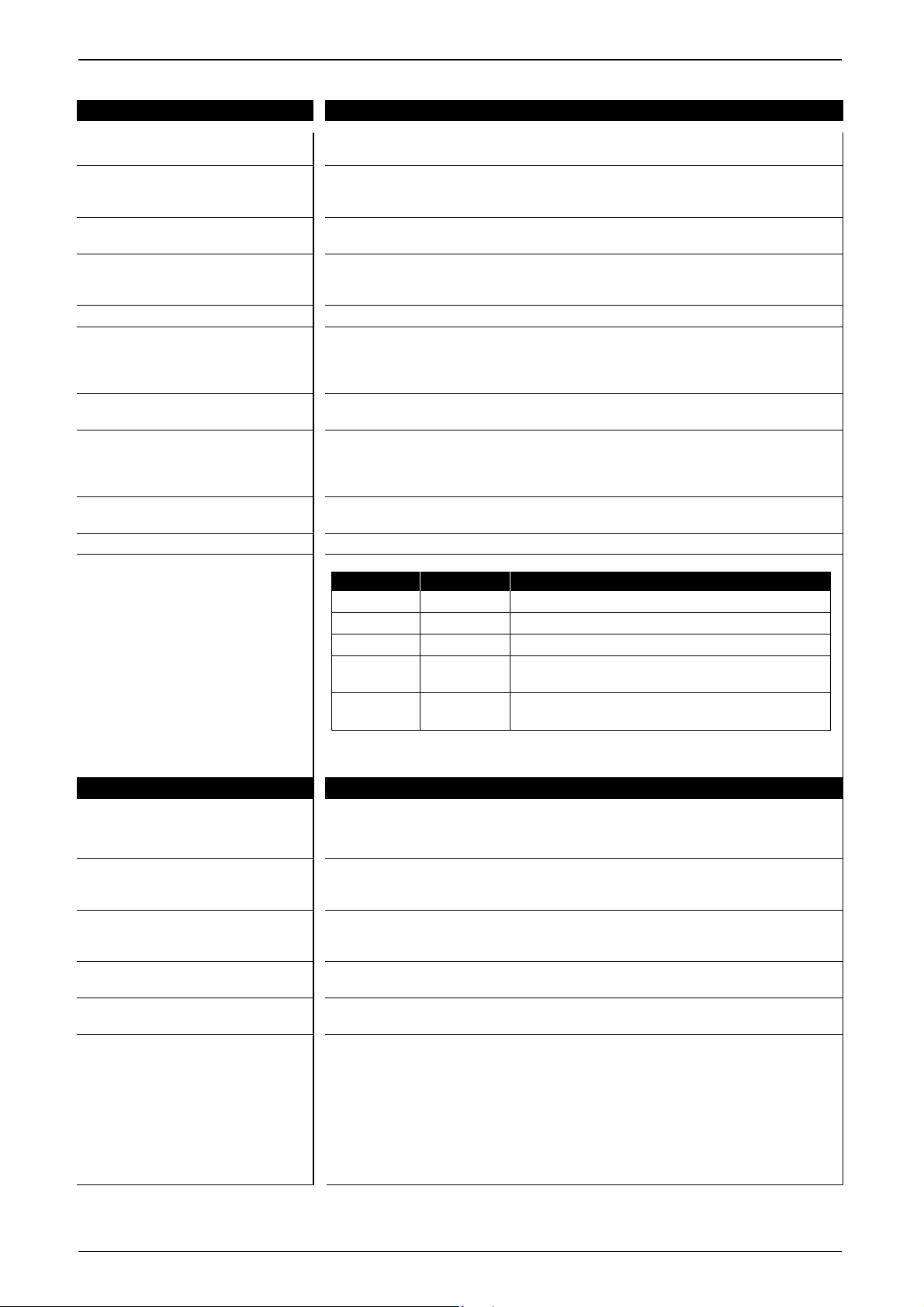
CR0302 Anschlussbelegung
Erläuterung der Abkürzungen:
A = analog
BH = binär (High Side)
BL = binär (Low Side)
FRQ/CYL = Frequenzeingänge
IL = Impuls (Low Side)
PH = PWM (High Side)
PWM = Puls-weiten-modulierte Signale
RxD = serielle Schnittstelle (Empfangsdaten)
TxD = serielle Schnittstelle (Sendedaten)
Page 10

CABINETCONTROLLER CR0302
PAGE 10
Safety instructions
This description is part of the unit. It contains texts and drawings
concerning the correct handling of the controller and must be
read before installation or use.
Observe the information of the description. Non-observance of the notes,
operation which is not in accordance with use as prescribed below, wrong
installation or handling can result in serious harm concerning the safety of
persons and plant.
The instructions are for authorised persons according to the EMC and low
voltage guidelines. The controllers must be installed and commissioned by a
skilled electrician (programmer or service technician).
If the unit is not supplied by the mobile on-board system (12/24 V battery
operation) it must be ensured that the external voltage is generated and supplied according to the criteria for safety extra-low voltage (SELV) as this is supplied without further measures to the connected controller, the sensors, and
the actuators.
The wiring of all signals in connection with the SELV circuit of the unit must
also comply with the SELV criteria (safe extra-low voltage, safe electrical separation from other electric circuits).
If the supplied SELV voltage has an external connection to ground (SELV
becomes PELV) the responsibility lies with the user and the respective national
regulations for installation must be complied with. All statements in these
operating instructions refer to the unit the SELV voltage of which is not
grounded.
The terminals may only be supplied with the signals indicated in the technical
data or on the unit label and only the approved accessories of ifm electronic
gmbh may be connected.
The unit can be operated within a wide temperature range according to the
technical specification indicated below. Due to the additional self-heating the
housing walls can have high perceptible temperatures when touched in hot
environments.
In case of malfunctions or uncertainties please contact the manufacturer.
Tampering with the unit can lead to considerable risks for the safety of persons and plant. It is not permitted and leads to the exclusion of any liability
and warranty claims.
Page 11

Contents
1. Function and features page 11
2. Programming page 11
3. Mounting page 12
4. Electrical connection page 12
5. Maintenance, repair and disposal page 12
6. Approvals/standards page 12
Technical data (data sheets 1...5)
Dimensions, mechanics, electronics page 13
Operating status (status LED) page 14
Test standards and regulations page 14
Characteristics of the inputs/outputs page 15
Wiring page 17
1. Function and features
The freely programmable controllers of the "CabinetController R 360" series are
rated for use under difficult conditions (e.g. extended temperature range, strong
vibration, intensive EMC interference).
They are thus suited for direct mounting into machines in mobile and rugged
applications. Due to their specification the inputs and outputs are especially rated
for this use. Integrated hardware and software functions (operating system) offer
high protection of the machine.
The controllers can be used as CANopen master.
The controllers "CabinetController R 360" are not approved for safety-relevant tasks in the field of safety of persons.
2. Programming
The application software can be easily created by the user with the programming
system CODESYS according to IEC 61131-3.
In addition to the programming system the complete system manual is required
to program the controller.
If this manual is not available, please contact one of the ifm branch offices overleaf for your free copy. The system manual (pdf format) can also be downloaded
from the web (www.ifm.com)..
➔ System manual R360; English (order no. EC2041)
➔ Data sheet direct ➔ CR0302 ➔ Additional data
The user is responsible for the safe functioning of the application programs
which he creates himself. If necessary, he must additionally obtain an
approval according to the corresponding national regulations by the corresponding testing and supervisory organisations.
Internet
Request
ENGLISH
CABINETCONTROLLER CR0302
PAGE 11
Page 12

CABINETCONTROLLER CR0302
PAGE 12
3. Mounting
The controller is to be mounted in a dry and enclosed environment (e.g. control
panel of the driver's cab, separate control boxes etc.).
It is mounted with 4 screws M4 x L.
4. Electrical connection
To protect the whole system (wiring and controller) the individual electric circuits
must be protected.
5. Maintenance, repair and disposal
As the Controller does not contain any components which must be maintained
by the user, the housing must not be opened. The maintenance of the controller
may only be carried out by the manufacturer. The disposal must be carried out
according to the corresponding national environmental regulations.
6. Approvals/standards
Test standards and provisions ➔ Technical data.
The CE Declaration of Conformity and the E1 approval are available at:
➔ Data sheet direct ➔ CR0302 ➔ Approvals
www.ifm.com
Designation Potential Connector :Pin no. Fuse
supply voltage U
B
X1:01 max. 2 A T
supply voltage digital outputs U
COM01/02
X3:05/10 max. 16 A
U
COM03
X5:02
Page 13

ENGLISH
CABINETCONTROLLER CR0302
PAGE 13
223
134
108
198
LED
Ø 4,5
X2 X4 X3
X5
X1
RS232
2
1
ifm electronic gmbh • Friedrichstraße 1 • 45128 Essen
05.11.2014
CR0302
Mobile controller
CabinetController
24 inputs
12 outputs
Programming
to IEC 61131-3
Operating voltage
10...32 V DC
We reserve the right to make technical alterations without prior notice. CR0302 / page 1
Technical data usable as CANopen master or intelligent I/O module
24 inputs (8 analogue / 16 digital) and 12 outputs (12 digital)
Design PCB without housing
(for mechanical protection potted in a potting tub)
Dimensions (l x w x h) 223 x 134 x 33 mm
Mounting fixing via 4 bore holes (Ø 4.5 mm)
Connections AMP crimp connector to be clipped into place and thus vibration-resistant,
protected against reverse polarity (AMP Junior Timer contacts)
Inputs / outputs 2 x 10 pins, 2 x 18 pins
Operating voltage and CAN bus 1 x 6 pins
Programming, TEST D-Sub socket, 9 pins
Weight 0.49 kg
Operating temperature – 40...85 °C (depending on the load)
Storage temperature – 40...85 °C
Protection IP 20
Inputs 24
possible configurations
Outputs 12
possible configurations
Accessories order no. EC2075
(to be ordered separately) connector set for CabinetController, consisting of:
AMP crimp housing, 1 x 6 pins, 2 x 10 pins, 3 x 18 pins
incl. crimp contacts (Junior Power Timer)
order no. EC2076
RS 232 programming adapter for the connection of U
B
to the TEST input
Amount Signal Type
8 analogue 0...10/32 V DC, 0...20 mA or ratiometric A
or
digital as binary voltage input B
L
8 digital for positive sensor signals, with diagnostic capability B
L
4 digital for positive sensor signals, with diagnostic capability B
L
or
frequency pulse inputs, max. 30 kHz I
L
4 digital for positive / negative sensor signals B
L/H
Amount Signal Type
4 digital positive switching (high side) B
H
or
PWM PWM frequency max. 250 Hz PWM
4 digital positive switching (high side) B
H
4 digital positive switching (high side) B
H
Abbreviations
A = analogue
B
H
= binary high side
B
L
= binary low side
I
L
= pulse low side
PWM = pulse width modulation
1) row of LEDs (10 segments) 2) DIP switch (8 segments)
Page 14

CABINETCONTROLLER CR0302
PAGE 14
ifm electronic gmbh • Friedrichstraße 1 • 45128 Essen
05.11.2014We reserve the right to make technical alterations without prior notice. CR0302 / page 2
CR0302 Technical data
Operating voltage U
B
10...32 V DC
Overvoltage 36 V for t ≤ 10 s
Undervoltage detection for U
B
≤ 9,5 V
Auto save for UB≤ 9,0 V
Current consumption ≤ 100 mA (without external load at 24 V DC)
external fuse with max. 10 A
CAN interface CAN interface 2.0 B, ISO 11898
Baud rate 50 Kbits/s...1 Mbit/s (default setting 125 Kbits/s)
Communication profile CANopen, CiA DS 301 version 3.0, CiA DS 401 version 1.4
Node ID (CANopen) hex 20 (= dec 32)
Serial interface RS 232C
Baud rate 9.6 / 19.2 / 28.8 / 38.4 / 57.6 kBit/s (default setting 57.6 Kbits/s)
Topology point-to-point (max. 2 participants); master-slave connection
Protocol predefined ifm protocol (INTELHEX)
Processor CMOS microcontroller 16 bits C167C
pulse frequency 20 MHz
Memory
Program memory 192 Kbytes Flash
Data memory 48 Kbytes SRAM, 32 Kbytes Flash, 4 Kbytes EEPROM
Data memory (auto save memory) 256 bytes (protected in case of power failure)
Indicators / input elements 10-segment row of LEDs
(freely configurable) 8-segment DIP switch
Status LED two-colour LED (red / green)
Operating states (status LED)
Test standards and regulations
Climatic test damp heat to EN 60068-2-30, test Db
(≤ 95% rel. humidity, non-condensing)
protection test to EN 60529
Mechanical resistance vibration to EN 60068-2-6, test Fc
shock to EN 60068-2-27, test Ea
bump to EN 60068-2-29, test Eb
Immunity to to ISO 7637-2: 2004, pulses 2a, 3a, 3b, severity level 4, function state A
conducted interference to ISO 7637-2: 2004, pulse 5, severity level 1, function state A
to ISO 7637-2: 2004, pulse 1, 2b, severity level 4, function state C
Immunity to interfering fields according to UN/ECE-R10 at 100 V/m (E1 type approval)
and EN 61000-6-4 (CE)
Interference emission according to UN/ECE-R10 (E1 type approval)
and EN 61000-6-2 (CE)
LED colour Status Description
– off no operating voltage
orange 1 x on initialisation or reset checks
green 5 Hz no operating system loaded
green 2.0 Hz Run
on Stop
red 2.0 Hz Run with error
on fatal error or stop with error
Page 15

ENGLISH
CABINETCONTROLLER CR0302
PAGE 15
CR0302 Characteristics of the inputs
Analogue inputs ■ Voltage inputs
X2:01...10, A_IN 00...A_IN07 input voltage 0...10 V or 0...32 V
can be configured as ... resolution 10 bits
accuracy ± 1% FS
input resistance 78.4 kΩ (0...10 V), 46.6 kΩ (0...32 V)
input frequency 50 Hz
■ Current inputs, with diagnostic capability
input current 0...20 mA
resolution 10 bits
accuracy ± 1% FS
input resistance 400 Ω
input frequency 50 Hz
At a current of > 23 mA the pair of channels is switched to the voltage input!
■ Voltage inputs, 0...32 V, ratiometric
function (U
IN
÷ UB) x 1000 ‰
value range 0...1000 ‰
■ Binary voltage inputs for positive sensor signals
The analogue inputs A_IN 00...07 are configured / switched in pairs!
The following inputs are combined in pairs: 0+4, 1+5, 2+6, 3+7
Digital inputs ■ Digital inputs for positive sensor signals, with diagnostic capability
X4:01...08, IN 00...IN07 switch-on level > 0.6 U
B
can be configured as ... switch-off level < 0.3 U
B
input resistance 3.21 kΩ
input frequency 50 Hz
Digital inputs ■ Digital inputs for positive sensor signals, with diagnostic capability
X4:11...14, IN 08...IN11 switch-on level > 0.6 U
B
can be configured as ... switch-off level < 0.3 U
B
input resistance 3.16 kΩ
input frequency 50 Hz
■ Frequency inputs for positive sensor signals, with diagnostic capability
switch-on level 0.4...0.7 U
B
switch-off level 0.2...0.24 U
B
input resistance 3.16 kΩ
measuring range 0...2 kHz oder 1...30 kHz
Digital inputs ■ Digital inputs for positive sensor signals
X4:15...18, IN 12...IN15 switch-on level > 0.6 U
B
can be configured as ... switch-off level < 0.3 U
B
input resistance 3.21 kΩ
input frequency 50 Hz
■ Digital inputs for negative sensor signals
switch-on level < 0.2 U
B
switch-off level > 0.5 U
B
input resistance 3.21 kΩ
input frequency 50 Hz
The digital inputs IN 12...15 are configured / switched in pairs!
The following inputs are combined in pairs: 12+13, 14+15
Test input During the test mode (e.g. programming) the TEST input must be connected to U
B
RS 232, D-Sub plug, pin 09 (10...32 V DC).
For the "RUN" mode the TEST input must not be connected.
also see wiring, page 5
ifm electronic gmbh • Friedrichstraße 1 • 45128 Essen
05.11.2014We reserve the right to make technical alterations without prior notice. CR0302 / page 3
Page 16

CABINETCONTROLLER CR0302
PAGE 16
CR0302 Characteristics of the outputs
Digital outputs ■ Semi conductor outputs, positive switching (high side), with diagnostic capability
X3:01...04, OUT 00...OUT03 short-circuit and overload protected
can be configured as ... switching voltage 10...32 V DC
switching current max. 2 A
■ PWM outputs
PWM frequency max. 250 Hz
setting resolution 0,1 %
load current max. 2 A
The outputs 0...3 are combined and have a common U
COM
connection.
Digital outputs ■ Semi conductor outputs, positive switching (high side),
X3:06...09, OUT 04...OUT07 short-circuit and overload protected
switching voltage 10...32 V DC
switching current max. 2 A
The outputs 4...7 are combined and have a common U
COM
connection.
Digital outputs ■ Semi conductor outputs, positive switching (high side),
X5:01...18, OUT 08...OUT11 short-circuit and overload protected
Schaltspannung 10...32 V DC
Schaltstrom max. 2 A
The outputs 8...11 are combined and have a common U
COM
connection.
External free-wheeling diode To protect the outputs free-wheeling diodes must be connected in parallel with the
load in the case of high switch-off energies (inductive or capacitive loads).
also see wiring, page 5
ifm electronic gmbh • Friedrichstraße 1 • 45128 Essen
05.11.2014We reserve the right to make technical alterations without prior notice. CR0302 / page 4
Page 17

ENGLISH
CABINETCONTROLLER CR0302
PAGE 17
ifm electronic gmbh • Friedrichstraße 1 • 45128 Essen
05.11.2014We reserve the right to make technical alterations without prior notice. CR0302 / page 5
X2
Analog-Eingänge
X4
Digital-Eingänge
X3
Digital-Ausgänge
X5
Digital-Ausgänge
X1
Betriebsspannung
CAN-Bus
RS 232
Programmierung
TEST-Eingang
1,00 A
Multifuse
02
RxD
03
TxD
05
GND
06
UB
09
TEST
01
02
03
A
A
A
A_IN00
A_IN01
A_IN02
04
A A_IN 03
05
UB
06
GND
07
A A_IN 04
08
A A_IN 05
09
A A_IN 06
10
A A_IN 07
01
02
03
BL
BL
BL
IN00
IN01
IN02
04
BL IN03
05
BL IN04
06
BL IN05
07
BL IN06
08
BL IN07
09
UB
10
GND
11
BL/IL IN08
12
BL/IL IN09
13
BL/IL IN10
14
BL/IL IN11
15
BL/BH IN 12
16
BL/BH IN 13
17
BL/BH IN 14
18
BL/BH IN 15
01
UB
02
GND
03
CAN_L
04
CAN_H
05
CAN_L
06
CAN_H
01
02
03
BH/PH
BH/PH
BH/PH
OUT00
OUT01
OUT02
04
BH/PH OUT03
05
UCOM01
06
BH OUT04
07
BH OUT05
08
BH OUT06
09
BH OUT07
10
UCOM02
PWM0
PWM1
PWM2
PWM3
FRQ0 / CYL0
FRQ1 / CYL1
FRQ2 / CYL2
FRQ3 / CYL3
Steckerbelegung
(Ansicht von oben auf Stiftseite)
1
3
5
2
4
6
01
02
03
n.c.
U
COM 03
n.c.
04
BH OUT08
05
n.c.
06
n.c.
07
n.c.
08
BH OUT09
09
n.c.
10
n.c.
11
n.c.
12
BH OUT10
13
n.c.
14
n.c.
15
n.c.
16
BH OUT11
17
n.c.
18
n.c.
CR0302 Wiring
Explanation of the abbreviations:
A = analogue
BH = binary (high side)
BL = binary (low side)
FRQ/CYL = frequency inputs
IL = pulse (low side)
PH = PWM (high side)
PWM = pulse width modulated signals
RxD = serial interface (data received)
TxD = serial interface (data transmitted)
X2
analogue inputs
X4
digital inputs
X3
digital outputs
X5
digital outputs
X1
operating voltage
CAN bus
RS 232
programming
TEST input
pin connection
(view from the top on pin side)
 Loading...