

Page 1

Original Programming Manual
CabinetController
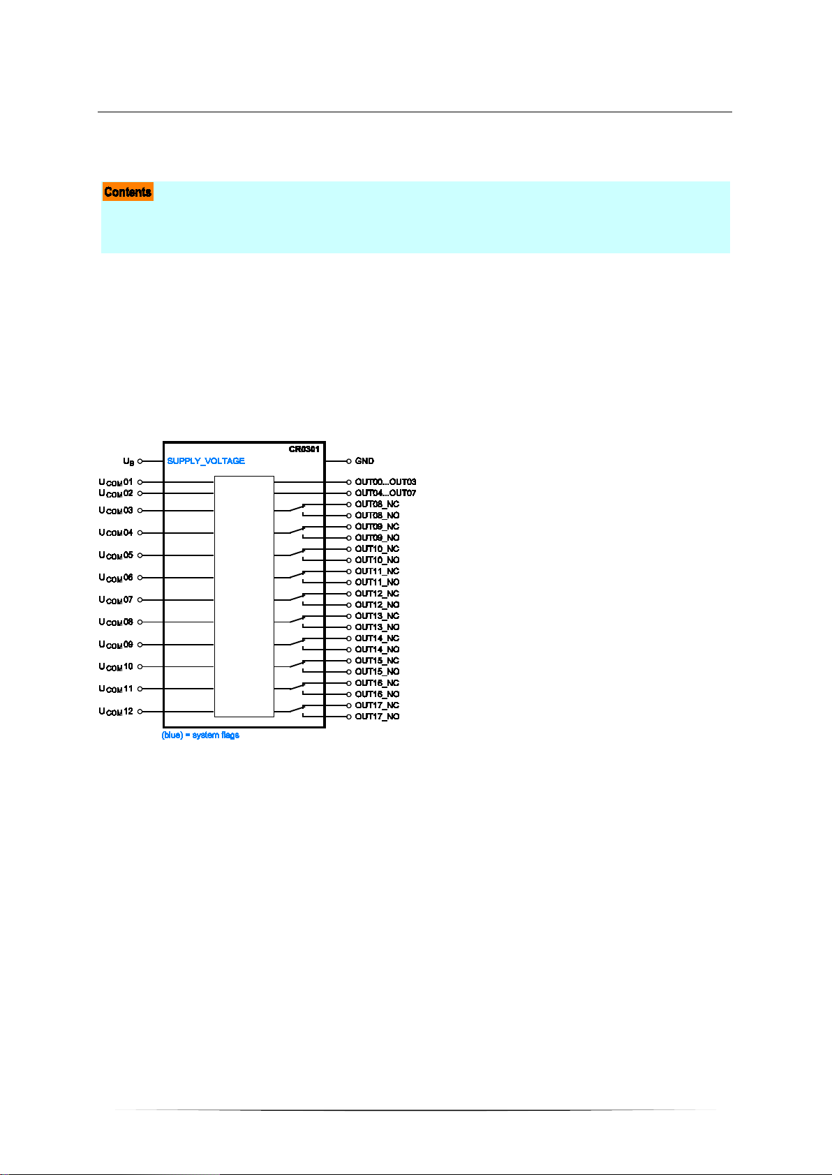
CR0301
Runtime system V05
CODESYS® > V2.3.9.33 (< V 3.0)
English
7391083_01_UK 2016-04-21
1
Page 2

ifm Programming Manual ecomatmobile CabinetController (CR0301) Runtime System V05 2016-04-21
Contents
Contents
1 About this manual 4
1.1 Copyright .............................................................................................................................. 4
1.2 Overview: documentation modules for ecomatmobile devices ............................................ 5
1.3 CODESYS programming manual ........................................................................................ 5
1.4 What do the symbols and formats mean? ........................................................................... 6
1.5 How is this documentation structured? ................................................................................ 7
1.6 History of the instructions (CR030n) .................................................................................. 8
2 Safety instructions 9
2.1 Please note! ......................................................................................................................... 9
2.2 What previous knowledge is required? ..............................................................................10
2.3 Start-up behaviour of the controller....................................................................................10
2.4 Notes: serial number ..........................................................................................................11
2.5 Notes: TEST inputs ............................................................................................................11
3 System description 12
3.1 Information about the device ..............................................................................................12
3.2 Hardware description .........................................................................................................12
3.2.1 Hardware structure ..................................................................................................................... 13
3.2.2 Monitoring concept ..................................................................................................................... 15
3.2.3 Inputs (technology) ..................................................................................................................... 17
3.2.4 Outputs (technology) .................................................................................................................. 21
3.2.5 Note on wiring ............................................................................................................................ 24
3.2.6 Safety instructions about Reed relays ........................................................................................ 24
3.2.7 Status LED ................................................................................................................................. 25
3.3 Interface description ...........................................................................................................26
3.3.1 Serial interface ........................................................................................................................... 26
3.3.2 CAN interfaces ........................................................................................................................... 27
3.4 Software description ..........................................................................................................28
3.4.1 Software modules for the device ................................................................................................ 28
3.4.2 Programming notes for CODESYS projects ............................................................................... 31
3.4.3 Operating states ......................................................................................................................... 35
3.4.4 Operating modes ........................................................................................................................ 39
3.4.5 Performance limits of the device ................................................................................................ 41
4 Configurations 42
4.1 Set up the runtime system .................................................................................................42
4.1.1 Reinstall the runtime system ...................................................................................................... 43
4.1.2 Update the runtime system ......................................................................................................... 44
4.1.3 Verify the installation .................................................................................................................. 44
4.2 Set up the programming system ........................................................................................45
4.2.1 Set up the programming system manually ................................................................................. 45
4.2.2 Set up the programming system via templates ........................................................................... 47
4.3 Function configuration of the inputs and outputs ...............................................................48
4.3.1 Configure inputs ......................................................................................................................... 49
4.3.2 Configure outputs ....................................................................................................................... 52
4.4 Note on wiring ....................................................................................................................54
4.5 Safety instructions about Reed relays ...............................................................................54
2
Page 3

ifm Programming Manual ecomatmobile CabinetController (CR0301) Runtime System V05 2016-04-21
Contents
5 ifm function elements 55
5.1 ifm libraries for the device CR0301 ....................................................................................55
5.1.1 Bibliothek ifm_CR0301_V05yyzz.LIB ......................................................................................... 56
5.1.2 Library ifm_CR0301_CANopenMaster_V04yynn.LIB ................................................................. 58
5.1.3 Library ifm_CR0301_CANopenSlave_V04yynn.LIB ................................................................... 58
5.1.4 Library ifm_CAN1_EXT_Vxxyyzz.LIB ......................................................................................... 59
5.1.5 Bibliothek ifm_J1939_1_Vxxyyzz.LIB ......................................................................................... 59
5.2 ifm function elements for the device CR0301 ....................................................................60
5.2.1 Function elements: CAN layer 2 ................................................................................................. 60
5.2.2 Function elements: CANopen master ......................................................................................... 76
5.2.3 Function elements: CANopen slave ........................................................................................... 86
5.2.4 Function elements: CANopen SDOs .......................................................................................... 94
5.2.5 Function elements: SAE J1939 .................................................................................................. 99
5.2.6 Function elements: serial interface ........................................................................................... 111
5.2.7 Function elements: Optimising the PLC cycle via processing interrupts .................................. 116
5.2.8 Function elements: processing input values ............................................................................. 122
5.2.9 Function elements: adapting analog ue val ues ......................................................................... 127
5.2.10 Function elements: counter functions for frequency and period measurement ........................ 130
5.2.11 Function elements: PWM functions .......................................................................................... 140
5.2.12 Function elements: controllers .................................................................................................. 149
5.2.13 Function elements: softwar e reset ............................................................................................ 158
5.2.14 Function elements: measuring / setting of time ........................................................................ 160
5.2.15 Function elements: saving, rea ding and conv ert ing data in the memory .................................. 163
5.2.16 Function elements: data access and data check ...................................................................... 170
6 Diagnosis and error handling 177
6.1 Diagnosis .........................................................................................................................177
6.2 Fault .................................................................................................................................177
6.3 Reaction in case of an error .............................................................................................178
6.4 Reaction in case of a system error ..................................................................................178
6.5 CAN / CANopen: errors and error handling .....................................................................178
7 Appendix 179
7.1 System flags .....................................................................................................................179
7.1.1 System flags: CAN ................................................................................................................... 180
7.1.2 System flags: error flags ........................................................................................................... 180
7.1.3 System flags: status LED ......................................................................................................... 181
7.1.4 System flags: voltages.............................................................................................................. 181
7.1.5 System flags: inputs and outputs .............................................................................................. 182
7.1.6 System flags: system ............................................................................................................... 182
7.2 Address assignment and I/O operating modes ................................................................183
7.2.1 Addresses / variables of the I/Os .............................................................................................. 183
7.2.2 Possible operating modes inp uts/o utpu t s ................................................................................. 187
7.3 Error tables .......................................................................................................................190
7.3.1 Error flags ................................................................................................................................. 190
7.3.2 Errors: CAN / CANopen............................................................................................................ 190
8 Glossary of Terms 191
9 Index 204
10 Notizen • Notes • Notes 208
11 ifm weltweit • ifm worldwide • ifm à l’échelle internationale 213
3
Page 4

ifm Programming Manual ecomatmobile CabinetController (CR0301) Runtime System V05 2016-04-21
History of the instructions (CR030n) ................................................................................................... 8
About this manual Copyright
1 About this manual
Copyright ............................................................................................................................................... 4
Overview: documentation modules for ecomatmobile devices ............................................................. 5
CODESYS programming manual .......................................................................................................... 5
What do the symbols and formats mean? ............................................................................................. 6
How is this documentation structured? ................................................................................................. 7
>
1.1 Copyright
6088
© All rights reserved by ifm electronic gmbh. No part of this manual may be reproduced and used
without the consent of ifm electronic gmbh.
All product names, pictures, companies or other brands used on our pages are the property of the respective rights owners:
• AS-i is the property of the AS-International Association, (→ www.as-interface.net
• CAN is the property of the CiA (CAN in Automation e.V.), Germany (→ www.can-cia.org)
• CODESYS™ is the property of the 3S – Smart Software Solutions GmbH, Germany (→ www.codesys.com)
• DeviceNet™ is the property of the ODVA™ (Open DeviceNet Vendor Association), USA (→ www.odva.org)
• EtherNet/IP® is the property of the →ODVA™
®
• IO-Link
(→ www.io-link.com) is the property of the →PROFIBUS Nutzerorganisation e.V., Germany
• ISOBUS is the property of the AEF – Agricultural Industry Electronics Foundation e.V., Deutschland
(→ www.aef-online.org)
• Microsoft® is the property of the Microsoft Corporation, USA (→ www.microsoft.com)
• PROFIBUS® is the property of the PROFIBUS Nutzerorganisation e.V., Germany (→ www.profibus.com)
• PROFINET® is the property of the →PROFIBUS Nutzerorganisation e.V., Germany
®
• Windows
is the property of the →Microsoft Corporation, USA
)
202
4
Page 5

ifm Programming Manual ecomatmobile CabinetController (CR0301) Runtime System V05 2016-04-21
About this manual Overview: documentation modules for ecomatmobile devic es
>
1.2 Overview: documentation m odules for ecomatmobile devices
The documentation for ecomatmobile devices consists of the following modules:
1. Data sheet
Contents Technical data in a table
Source → www.ifm.com > select your country > [Data sheet search] > CR0301 > [Technical data in PDF format]
2. Installation instructions / operating instructions
Contents Instructions for installation, electrical installation, (commissioning*), technical data
Source The instructions are supplied with the device
They are also found on ifm's homepage:
→ www.ifm.com
3. Programming manual + online help
Contents Description of the configuration and the functions of the device software
Source → www.ifm.com > select your country > [Data sheet search] > CR0301 > [Operating instructions]
4. System manual "Know-how ecomatmobile"
> select your country > [Data sheet search] > CR0301 > [Operating instructions]
17405
Contents Know-how about the following topics:
• Overview Templates and demo programs
• CAN, CANopen
• Control outputs
• User flash memory
• Visualisations
• Overview of the files and libraries used
Source → www.ifm.com > select your country > [Data sheet search] > CR0301 > [Operating instructions]
5. System manual "The ISOBUS in the ifm controller"
Contents Description of the configuration and the functions of the ISOBUS software in the device
Source → www.ifm.com > select your country > [Data sheet search] > CRnnnn > [Operating instructions]
thereby "CRnnnn" stands for the articel numbers of the devices which are pre-installed with ISOBUS
*) The descriptions in brackets are only included in the instructions of certain devices.
>
1.3 CODESYS programming manual
17542
In the additional "Programming Manual for CODESYS V2.3" you obtain more details about the use of
the programming system.
This manual can be downloaded free of charge from ifm's website:
→ www.ifm.com
You also find manuals and online help for ecomatmobile at:
→ ecomatmobile DVD "Software, tools and documentation"
> Select your country > [Service] > [Download] > [Systems for mobile machines]
5
Page 6

ifm Programming Manual ecomatmobile CabinetController (CR0301) Runtime System V05 2016-04-21
About this manual What do the sy m bols and formats mean?
>
1.4 What do the symbols and formats mean?
The following symbols or pictograms illustrate the notes in our instructions:
WARNING
Death or serious irreversible injuries may result.
CAUTION
Slight reversible injuries may result.
NOTICE
Property damage is to be expected or may result.
Important notes concerning malfunctions or disturbances
Other remarks
► ... Request for action
203
> ... Reaction, result
→ ... "see"
abc Cross-reference
123
0x123
0b010
[...] Designation of pushbuttons, buttons or indications
Decimal number
Hexadecimal number
Binary number
6
Page 7

ifm Programming Manual ecomatmobile CabinetController (CR0301) Runtime System V05 2016-04-21
About this manual How is this documentation structured?
>
1.5 How is this documentation str uctured?
This documentation is a combination of different types of manuals. It is for beginners and also a
reference for advanced users. This document is addressed to the programmers of the applications.
How to use this manual:
• Refer to the table of contents to select a specific subject.
• Using the index you can also quickly find a term you are looking for.
• At the beginning of a chapter we will give you a brief overview of its contents.
• Abbreviations and technical terms → Appendix.
In case of malfunctions or uncertainties please contact the manufacturer at:
→ www.ifm.com
We want to become even better! Each separate section has an identification number in the top right
corner. If you want to inform us about any inconsistencies, indicate this number with the title and the
language of this documentation. Thank you very much for your support!
We reserve the right to make alterations which can result in a change of contents of the
documentation. You can find the current version on ifm's websi te at:
→ www.ifm.com
> Select your country > [Contact].
> Select country > [Data sheet search] > (Article no.) > [Operating instructions]
204
1508
7
Page 8

ifm Programming Manual ecomatmobile CabinetController (CR0301) Runtime System V05 2016-04-21
About this manual History of t he instructions (CR030n)
>
1.6 History of the instructions (CR030n)
9181
What has been changed in this manual? An overview:
Date Theme Change
2010-09-09 PID2 (FB) parameters of the inputs corrected
2010-11-10 Terminating resistors correction in topic 1244
2011-02-14 TIMER_READ_US (FB) conversion of max. counter value corrected
2011-04-05 Memory POUs FRAMREAD, FRAMWRITE,
FLASHREAD, FLASHWRITE
2011-04-13 CANopen overview new: CANopen tables in the appendix
2011-04-14 CR0303 several corrections: - device has an own hydraulic library
2011-05-24 CR0303: memory FBs FRAMREAD, FRAMWRITE permitted values of the parameters SRC, DST
2012-01-09 Memory modules FRAMREAD, FRAMWRITE Swapped parameters SRC, DST in the table
2012-10-04 diverse corrections
2013-06-24 various new document structure
2014-04-28 Various function blocks More precise description of the function block input
2014-06-30 Name of the documentation "System manual" renamed as "Programming manual"
2014-07-18 CR0303: Error flag Wrong: ERROR_A_INx
2014-07-31 FB PHASE Description of parameters of outputs C, ET corrected
2014-08-26 Description of inputs, outputs highside / lowside replaced by positive / negative
2015-01-13 Structure of documentation for error codes, system
flags
2015-03-10 Available memory Description improved
2015-05-26 FB J1939_x_GLOBAL_REQUEST More precise description
2015-06-10 Various function blocks Description of the FB input CHANNEL corrected
>
permitted values of the parameters SRC, LEN, DST
- some system flags do not exist
- IEC addresses of in- and outputs
- configuration of the inputs
- set the status LED in the application program
corrected
"Permissible values"
CHANNEL
Correct: ERROR_Ix
switching
• error flags:
now only in the appendix, chapter System flags
• CAN / CANopen errors and error handling:
now only in the system manual "Know-How"
• error codes, EMCY codes:
now in the appendix, chapter Error tables
8
Page 9

ifm Programming Manual ecomatmobile CabinetController (CR0301) Runtime System V05 2016-04-21
Notes: TEST inputs ............................................................................................................................. 11
Safety instructions Please note!
2 Safety instructions
Please note! ........................................................................................................................................... 9
What previous knowledge is required? ............................................................................................... 10
Start-up behaviour of the controller ..................................................................................................... 10
Notes: serial number ........................................................................................................................... 11
>
213
2.1 Please note!
214
11212
No characteristics are warranted with the information, notes and examples provided in this manual.
With the drawings, representations and examples given no responsibility for the system is assumed
and no application-specific particularities are taken into account.
► The manufacturer of the machine/equipment is responsible for ensuring the safety of the
machine/equipment.
► Follow the national and international regulations of the country in which the machine/installation is
to be placed on the market!
WARNING
Non-observance of these instructions can lead to property damage or personal injury.
ifm electronic gmbh does not assume any liability in this regard.
► The acting person must have read and understood the safety instructions and the corresponding
chapters in this manual before working on and with this device.
► The acting person must be authorised to work on the machine/equipment.
► The acting person must have the qualifications and training required to perform this work.
► Adhere to the technical data of the devices!
You can find the current data sheet on ifm's homepage at:
→ www.ifm.com
in PDF format]
► Note the installation and wiring information as well as the functions and features of the devices!
→ supplied installation instr uc tions or on ifm's homepage:
→ www.ifm.com
instructions]
► Please note the corrections and notes in the release notes for the existing documentation,
available on the ifm website:
→ www.ifm.com
instructions]
> Select your country > [Data sheet search] > (article number.) > [Technical data
> Select your country > [Data sheet search] > (article number.) > [Operating
> Select your country > [Data sheet search] > (article number.) > [Operating
5020
NOTICE
The driver module of the serial interface can be damaged!
Disconnecting or connecting the serial interface while live can cause undefined states which damage
the driver module.
► Do not disconnect or connect the serial interface while live.
9
Page 10

ifm Programming Manual ecomatmobile CabinetController (CR0301) Runtime System V05 2016-04-21
Safety instructions What previous k nowledge is required?
>
2.2 What previous knowledge is required?
215
This document is intended for people with knowledge of control technology and PLC programming
with IEC 61131-3.
To program the PLC, the people should also be familiar with the CODESYS software.
The document is intended for specialists. These specialists are people who are qualified by their
training and their experience to see risks and to avoid possible hazards that may be caused during
operation or maintenance of a product. The document contains information about the correct handling
of the product.
Read this document before use to familiarise yourself with operating conditions, installation and
operation. Keep the document during the entire duration of use of the device.
Adhere to the safety instructions.
>
2.3 Start-up behaviour of the controller
6827
15233
11575
WARNING
Danger due to unintentional and dangerous start of machine or plant sections!
► When creating the program, the programmer must ensure that no unintentional and dangerous
start of machines or plant sections after a fault (e.g. e-stop) and the following fault elimination can
occur!
Realise restart inhibit.
► In case of an error, set the outputs concerned to FALSE in the program!
A restart can, for example, be caused by:
• voltage restoration after power failure
• reset after watchdog response because of too long a cycle time
• error elimination after an E-stop
To ensure a safe behaviour of the controller:
► Monitor the voltage supply in the application program.
► In case of an error switch off all relevant outputs in the application program.
► Monitor actuators which can cause hazardous movements in the application program (feedback).
► Monitor relay contacts which can cause hazardous movements in the application program
(feedback).
► If necessary, ensure that welded relay contacts in the application project cannot trigger or continue
hazardous movements.
10
Page 11

ifm Programming Manual ecomatmobile CabinetController (CR0301) Runtime System V05 2016-04-21
Safety instructions Notes: serial number
>
2.4 Notes: serial number
20780
► In the user's production facility, draw a diagram of the controller network in the machine. Enter the
serial number of each controller installed into the network diagram.
► Before downloading a software component, read out this serial number and check the network
diagram to make sure that you are accessing the right controller.
>
2.5 Notes: TEST inputs
20781
► The TEST inputs of all the controllers in the machine should be wired individually and marked
clearly so that they can be properly allocated to the controllers.
► During a service access only activate the TEST input of the controller to be accessed.
>
11
Page 12

ifm Programming Manual ecomatmobile CabinetController (CR0301) Runtime System V05 2016-04-21
Software description ............................................................................................................................ 28
Status LED .......................................................................................................................................... 25
System description Information ab o ut the dev ic e
3 System description
Information about the device ............................................................................................................... 12
Hardware description........................................................................................................................... 12
Interface description ............................................................................................................................ 26
>
3.1 Information about the device
This manual describes of the ecomatmobile family for mobile machines of ifm electronic gmbh:
• CabinetController: CR0301, CR0302
>
3.2 Hardware description
Hardware structure .............................................................................................................................. 13
Monitoring concept .............................................................................................................................. 15
Inputs (technology) .............................................................................................................................. 17
Outputs (technology) ........................................................................................................................... 21
Note on wiring ...................................................................................................................................... 24
Safety instructions about Reed relays ................................................................................................. 24
975
1310
14081
12
Page 13
ifm Programming Manual ecomatmobile CabinetController (CR0301) Runtime System V05 2016-04-21
Available memory ................................................................................................................................ 14
System description Hardware des cription
>
3.2.1 Hardware structure
Conditions ............................................................................................................................................ 13
Prinziple block diagram ....................................................................................................................... 13
>
Conditions
The device does not start until sufficient voltage is applied to the supply connection VBBs.
A voltage > 10 V is deemed sufficient.
Permissible operating voltage → data sheet
>
Prinziple block diagram
15332
19971
20848
Figure: Block diagram of the supply
13
Page 14

ifm Programming Manual ecomatmobile CabinetController (CR0301) Runtime System V05 2016-04-21
System description Hardware des cription
>
Available memory
>
FLASH-Speicher
13736
14024
FLASH memory (non-volatile, slow memory)
512 kByte
overall existing in the device
Thereof the following memory areas are reserved for ...
maximum size of the application program 192 kByte
data other than the application program
48 kByte
user can write data such as files, bitmaps, fonts
data other than the application program
read data with FLASHREAD (→ page 167
) or write data with FLASHWRITE
16 kByte
(→ page 168)
(files: 128 bytes less for header)
The remaining rest of the memory is reserved for system internal purposes.
>
SRAM
SRAM (volatile, fast memory)
overall existing in the device
SRAM indicates here all kinds of volatile and fast memories.
Thereof the following memory areas are reserved for ...
data reserved by the application program 48 kByte
The remaining rest of the memory is reserved for system internal purposes.
>
256 kByte
18705
EEPROM
EEPROM (non-volatile, slow memory)
overall existing in the device
Thereof the following memory areas are reserved for ...
variables in the application program, declared as VAR_RETAIN 256 Byte
remanent memory freely available to the user
Access is made via E2READ (→ page 165) and E2WRITE (→ page 166)
4 kByte
3 840 Byte
3957
14
Page 15

ifm Programming Manual ecomatmobile CabinetController (CR0301) Runtime System V05 2016-04-21
One-time mechanisms ........................................................................................................................ 16
System description Hardware des cription
>
3.2.2 Monitoring conce pt
The controller monitors the supply voltages and the system error flags.
Depending on the status...
• the controller switches off completely
> the program stops
> the outputs become currentless and change to logic "0"
> the status LED goes out
>
Monitoring and securing mechanisms
After application of the supply voltage................................................................................................. 15
If runtime system / application is running ............................................................................................ 16
If the TEST pin is not active ................................................................................................................ 16
For the these devices the following monitoring activities are automatically carried out:
>
19973
3926
After application of the supply voltage
After application of the supply voltage (controller is in the boot loader) the following tests are carried
out in the device:
> RAM test (one-time)
> supply voltage
> system data consistency
> CRC of the boot loader
> if exists and is started: CRC of the runtime system
> if exists and is started: CRC of the application program
> memory error:
• If the test is running: flag ERROR_MEMORY = TRUE
(can be evaluated as from the first cycle).
• If the test is not running: red LED is lit.
3927
15
Page 16

ifm Programming Manual ecomatmobile CabinetController (CR0301) Runtime System V05 2016-04-21
System description Hardware des cription
>
If runtime system / application is running
then the following tests are cyclically carried out:
> Triggering of the watchdog (100 ms)
Then continuous program check watchdog
> Continuous temperature check
In case of a fault: system flag ERROR_TEMPERATURE = TRUE
> Continuous voltage monitoring
In case of a fault: system flag ERROR_POWER = TRUE or ERROR_VBBR = TRUE
> Continuous CAN bus monitoring
> Continuous system data monitoring:
- program loaded
- operating mode RUN / STOP,
- runtime system loaded,
- node ID,
- baud rate of CAN and RS232.
> In the operating mode RUN:
Cyclical I/O diagnosis:
- short circuit,
- wire break,
- overload (current) of the inputs and outputs,
- cross fault (only for SafetyController).
>
3928
If the TEST pin is not active
> Write protection for system data in FRAM ¹), e.g.:
• runtime system loaded,
• calibration data.
Implemented via hardware and software.
> Write protection for application program (in the flash memory)
> DEBUG mode
¹) FRAM indicates here all kinds of non-volatile and fast memories.
>
One-time mechanisms
> CRC monitoring during download or upload.
> It must be checked that the runtime system and the application are assigned to the same device.
3929
3930
16
Page 17
ifm Programming Manual ecomatmobile CabinetController (CR0301) Runtime System V05 2016-04-21
Input group IN12...IN15 ....................................................................................................................... 20
System description Hardware des cription
>
3.2.3 Inputs (tec hnol ogy)
Analogue inputs ................................................................................................................................... 17
Binary inputs ........................................................................................................................................ 18
Input group ANALOG0...7 ................................................................................................................... 19
Input group IN00...IN07 ....................................................................................................................... 19
Input group IN08...IN11 / FRQ00...FRQ03 .......................................................................................... 19
>
14090
Analogue inputs
2426
The analogue inputs can be configured via the application program. The measuring range can be set
as follows:
• current input 0...20 mA
• voltage input 0...10 V
• voltage input 0...32 V
The voltage measurement can also be carried out ratiometrically (0...1000 ‰, adjustable via f unction
blocks). This means potentiometers or joysticks can be evaluated without additional reference voltage.
A fluctuation of the supply voltage has no influence on this measured value.
As an alternative, an analogue channel can also be evaluated binarily.
In case of ratiometric measurement the connected sensors should be supplied with VBBs of the
device. So, faulty measurements caused by offset voltage are avoided.
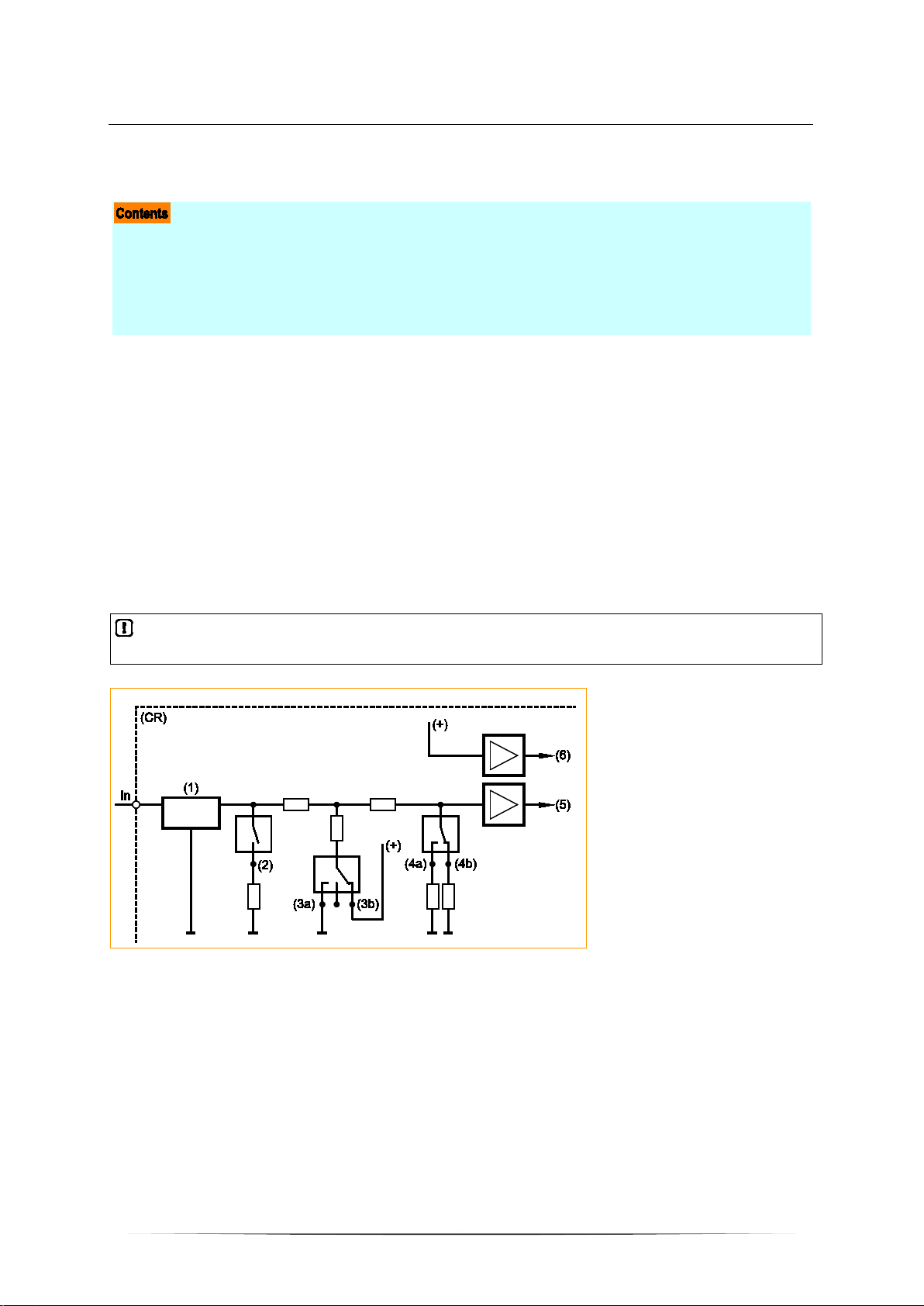
In = pin multifunction input n
(CR) = device
(1) = input filter
(2) = analogu e current measuring
(3a) = binary -input plus switching
(3b) = binary -input minus switching
(4a) = analog ue voltage meas ur ing 0. .. 10 V
(4b) = analog ue voltage measuring 0.. .32 V
(5) = voltage
(6) = reference voltage
8971
Figure: principle block diagram multifunction input
17
Page 18
ifm Programming Manual ecomatmobile CabinetController (CR0301) Runtime System V05 2016-04-21
System description Hardware des cription
>
Binary inputs
The binary input can be operated in following modes:
• binary input plus switching (BL) for positive sensor signal
• binary input minus switching (BH) for negative sensor signal
Depending on the device the binary inputs can configured differently. In addition to the protective
mechanisms against interference, the binary inputs are internally evaluated via an analogue stage.
This enables diagnosis of the input signals. But in the application software the switching signal is
directly available as bit information
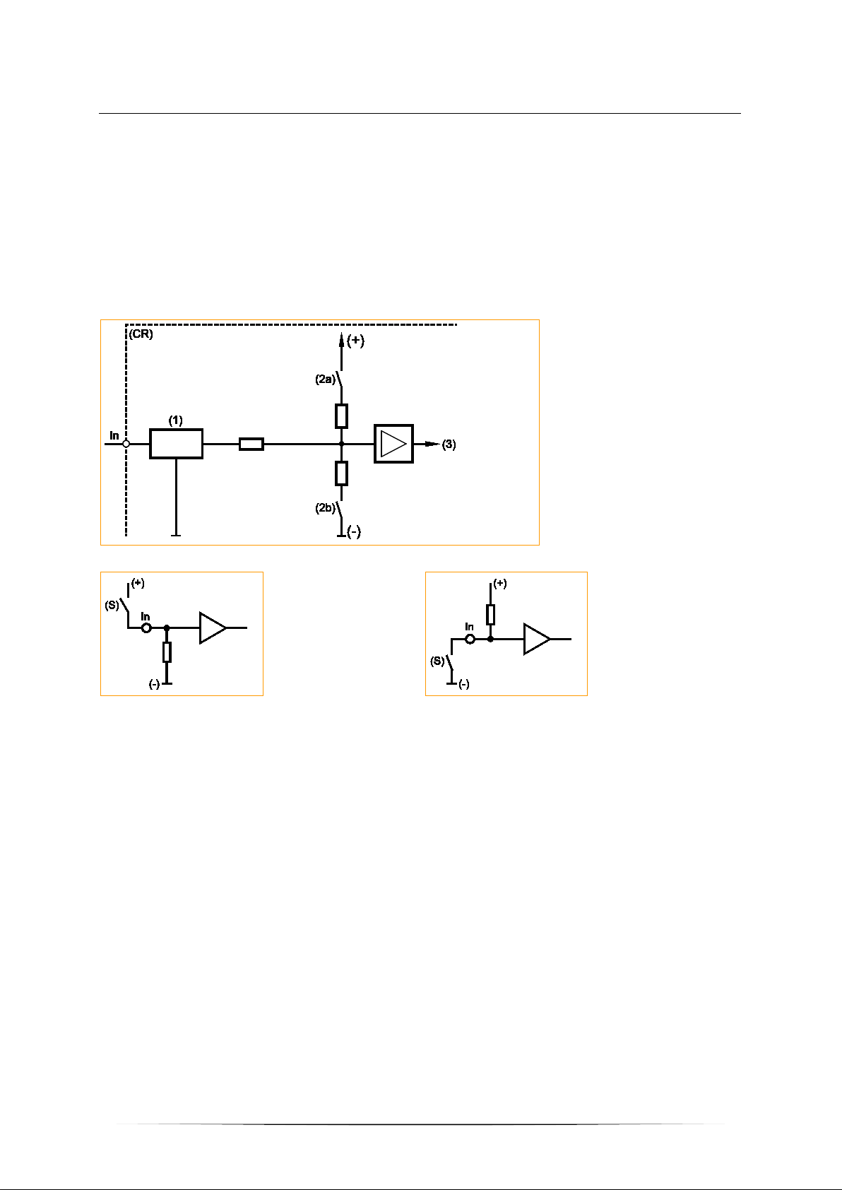
In = pin binary-input n
(CR) = device
(1) = input filter
(2a) = input minus switchi ng
(2b) = input plus switching
(3) = voltage
1015
7345
Figure: basic circuit of binary input minus switching / plus switching for negative and positive sensor signals
In = pin binary input n
(S) = sensor
Basic circuit of binary input plus switching (BL)
for positive sensor signal:
Input = open signal = low (GND)
For some of these inputs (→ data sheet) the potential can be selected to which it will be switched.
Basic circuit of binary input minus switching (BH)
for negative sensor signal:
Input = open signal = high (supply)
In = pin binary input n
(S) = sensor
18
Page 19

ifm Programming Manual ecomatmobile CabinetController (CR0301) Runtime System V05 2016-04-21
System description Hardware des cription
>
Input group ANALOG0...7
20856
These inputs are a group of multifunction channels.
These inputs can be used as follows (each input separately configurable):
• analogue input 0...20 mA
• analogue input 0...10 V
• analogue input 0...32 V
• voltage measurement ratiometric 0...1000 ‰ von 32 V
• binary input plus switching (BL) for positive sensor signal (with/without diagnosis)
→ chapter Possible operating modes inputs/outputs (→ page 187
All inputs show the same behaviour concerning function and diagnosis.
► Configuration of each input is made via the application program:
• configuration byte ANALOGxy_MODE
• FB INPUT_ANALOG (→ page 123
) > input MODE
If the analogue inputs are configured for current measurement, the device switches to the safe voltage
measurement range (0...32V DC) and the corresponding error bit in the flag byte ERROR_A_INx is set
when the final value (> 23 mA) is exceeded.
> When the value is again below the limit value, the input automatically switches back to the current
measurement range.
>
)
Input group IN00...IN07
19976
These inputs are a group of multifunction channels.
These inputs can be used as follows (each input separately configurable):
• binary input plus switching (BL) for positive sensor signal (with/without diagnosis)
→ chapter Possible operating modes inputs/outputs (→ page 187
)
► Configuration of each input is made via the application program :
• configuration byte INxx_MODE
Sensors with diagnostic capabilities to NAMUR can be evaluated.
>
Input group IN08...IN11 / FRQ00...FRQ03
19979
These inputs are a group of multifunction channels.
These inputs can be used as follows (each input separately configurable):
• binary input plus switching (BL) for positive sensor signal (with/without diagnosis)
• fast input for e.g. incremental encoders and frequency or interval measurement
→ chapter Possible operating modes inputs/outputs (→ page 187
Sensors with diagnostic capabilities to NAMUR can be evaluated.
► Configuration of each input is made via the application program:
• configuration byte INxx_MODE
• Fast inputs with the following FBs:
FAST_COUNT (→ page 131) Counter block for fast input pulses
FREQUENCY (→ page 132) Measures th e frequency of the signal arriving at the selected channel
INC_ENCODER (→ page 133) Up/down counter function for the evaluation of encoders
PERIOD (→ page 135) Measures the frequency and the cycle period (cycle time) in [µs] at the indicated ch annel
PERIOD_RATIO (→ page 137) Measures the frequency and the cycle period (cycle time) in [ µ s] during th e indicated p eriods at
PHASE (→ page 139) Reads a pair of channels with fast inputs and compares the phase position of the signals
the indicate d channel. In addition, the mark-to-space ratio is indicated in [‰].
)
19
Page 20

ifm Programming Manual ecomatmobile CabinetController (CR0301) Runtime System V05 2016-04-21
System description Hardware des cription
>
Input group IN12...IN15
These inputs are a group of multifunction channels.
These inputs can be used as follows (each input separately configurable):
• binary input plus switching (BL) for positive sensor signal
• binary input minus switching (BH) for negative sensor signal
→ chapter Possible operating modes inputs/outputs (→ page 187
Sensors with diagnostic capabilities to NAMUR can be evaluated.
All inputs show the same behaviour concerning function and diagnosis.
Detailed description → chapter Address assignment inputs / outputs
► Configuration of each input is made via the application program:
• inputs IN12+IN13 via configuration byte IN12_13_MODE
• inputs IN14+IN15 via configuration byte IN14_15_MODE
)
20858
20
Page 21
ifm Programming Manual ecomatmobile CabinetController (CR0301) Runtime System V05 2016-04-21
Output group OUT11...OUT17 ............................................................................................................ 23
System description Hardware des cription
>
3.2.4 Outputs (technology)
Binary outputs ...................................................................................................................................... 21
PWM outputs ....................................................................................................................................... 22
Output group OUT00...OUT03 ............................................................................................................ 22
Output group OUT04...OUT07 ............................................................................................................ 23
Output group OUT08...OUT10 ............................................................................................................ 23
>
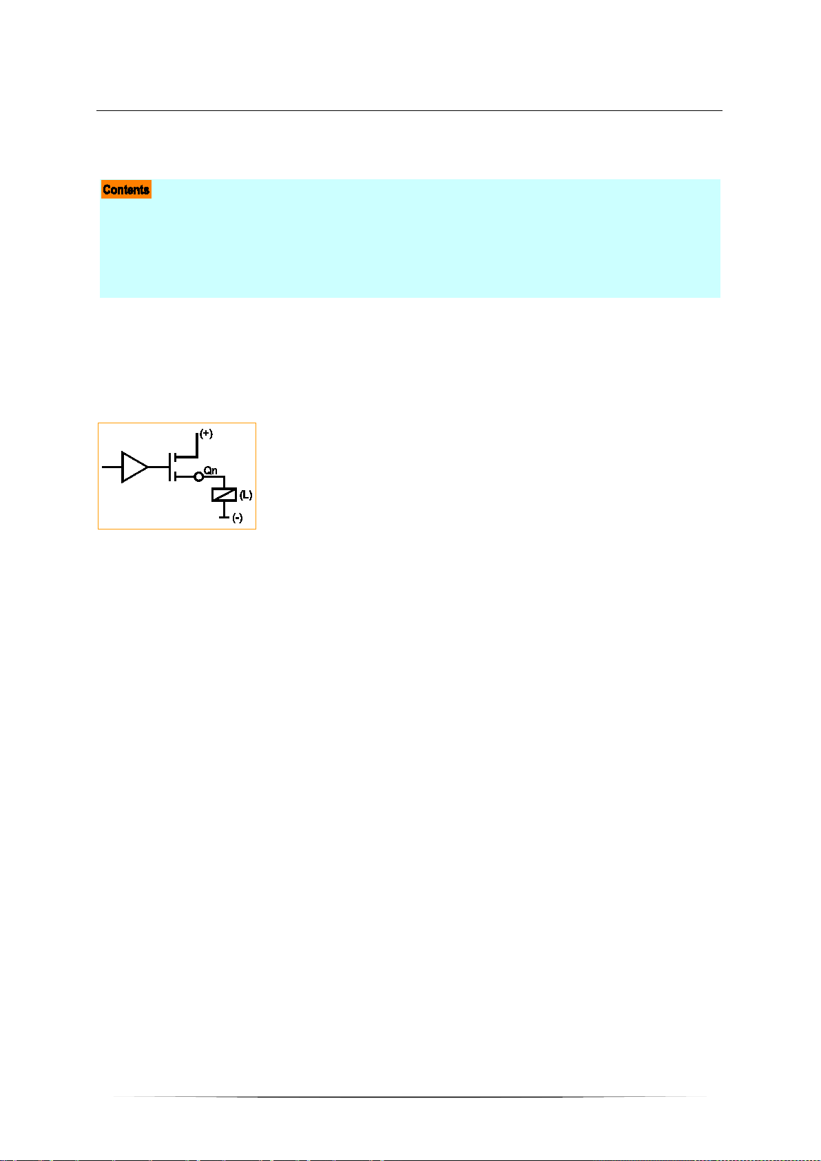
Binary outputs
The following operating modes are possible for the device outputs (→ data sheet):
• binary output, plus switching (BH), short-circuit proof, overload protected
Qn = pin output n
(L) = load
Basic circuit of output plus switching (BH)
for positive output signal
14093
19986
15451
21
Page 22

ifm Programming Manual ecomatmobile CabinetController (CR0301) Runtime System V05 2016-04-21
System description Hardware des cription
>
PWM outputs
The following operating modes are possible for the device outputs (→ data sheet):
• PWM output, plus switching (BH) without diagnostic function
Qn = pin output n
(L) = load
Basic circuit of output plus switching (BH)
for positive output signal
>
Output group OUT00...OUT03
These outputs are a group of multifunction channels.
These outputs provide several function options (each output separately configurable):
• binary output, plus switching (BH), short-circuit proof, overload protected
• analogue output with Pulse Width Modulation (PWM)
→ chapter Possible operating modes inputs/outputs (→ page 187
► Configuration of each output is made via the application program:
PWM outputs: selectively
→ FB PWM (→ page 141
)
→ FB PWM100 (→ page 145)
→ FB PWM1000 (→ page 147)
)
14095
15451
20860
► For the limit values please make sure to adhere to the data sheet!
22
Page 23

ifm Programming Manual ecomatmobile CabinetController (CR0301) Runtime System V05 2016-04-21
System description Hardware descripti on
>
Output group OUT04...OUT07
These outputs are a group of channels with a single specified function.
These outputs have the following fixed setting:
• binary output, plus switching (BH), short-circuit proof, overload protected
→ chapter Possible operating modes inputs/outputs (→ page 187
► For the limit values please make sure to adhere to the data sheet!
>
)
Output group OUT08...OUT10
These outputs are a group of channels with a single specified function.
These outputs have the following fixed setting:
• binary output with relay (change-over contacts)
• The outputs have no current measurement, no overload detection.
► For the limit values please make sure to adhere to the data sheet!
>
Output group OUT11...OUT17
These outputs are a group of channels with a single specified function.
These outputs have the following fixed setting:
• binary output with relay (change-over contacts)
• The outputs have no current measurement, no overload detection.
20863
20865
20867
► For the limit values please make sure to adhere to the data sheet!
23
Page 24

ifm Programming Manual ecomatmobile CabinetController (CR0301) Runtime System V05 2016-04-21
System description Hardware des cription
>
3.2.5 Note on wiring
1426
The wiring diagrams (→ installation instructions of the devices, chapter "Wiring") describe the standard
device configurations. The wiring diagram helps allocate the input and output channels to the IEC
addresses and the device terminals.
The individual abbreviations have the following meaning:
A Analogue input
BH Binary high side input: minus switching for negative sensor signal
BL Binary low side input: plus switching for positive sensor signal
CYL Input period measurement
ENC Input encoder signals
FRQ Frequency input
H bridge Output with H-bridge function
PWM
PWMi PWM output with current measurement
IH Pulse/counter input, high side: minus switching for negative sensor signal
IL Pulse/counter input, low side: plus switching for positive sensor signal
R Read back channel for one output
Binary high side output: plus switching for posit i ve output signal
Binary low side output: minus switching for negative output signal
Pulse-width modulated signal
Allocation of the input/output channels: → Catalogue, mounting instructions or data sheet
>
3.2.6 Safety instructions about Reed relays
For use of non-electronic switches please note the following:
Contacts of Reed relays may be clogged (reversibly) if connected to the device inputs without
series resistor.
► Remedy: Install a series resistor for the Reed relay:
Series resistor = max. input voltage / permissible current in the Reed relay
Example: 32 V / 500 mA = 64 Ohm
► The series resistor must not exceed 5 % of the input resistance RE of the device input (→ data
sheet). Otherwise, the signal will not be detected as TRUE.
Example:
RE = 3 000 Ohm
⇒ max. series resistor = 150 Ohm
7348
24
Page 25
ifm Programming Manual ecomatmobile CabinetController (CR0301) Runtime System V05 2016-04-21
System description Hardware des cription
>
3.2.7 Status LED
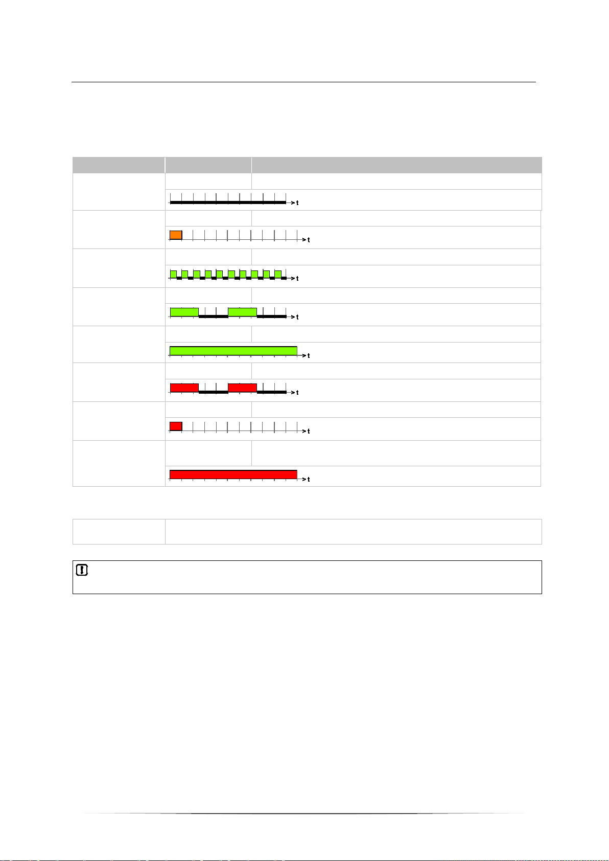
The operating states are indicated by the integrated status LED (default setting).
LED colour Display Description
Permanently off No operat i ng voltage
Off
Briefly on Initialisation or reset checks
Orange
(time frame = 200 ms)
Flashing with 5 Hz TEST=TRUE: no runtim e system loaded
Green
(time frame = 200 ms)
Flashing with 2 Hz Application = RUN
Green
(time frame = 200 ms)
Permanently on Appl i cation = STOP
Green
Flashing with 2 Hz Application = RUN with error
Red
(time frame = 200 ms)
Briefly on FATAL ERROR
Red
(time frame = 200 ms)
Permanently on
Red
TEST=TRUE: Application = STOP and FATAL ERROR
TEST=FALSE: ERROR STOP / SYSTEM STOP
1437
The status LED can be changed by the programming system for the operating states STOP and RUN.
To do so, the following system variable is used:
LED_MODE Flashing frequency from the data structure "LED_MODES"
permissible: LED_2HZ, LED_1HZ, LED_05HZ, LED_0HZ (constant)
If the flashing mode is changed in the application program, the default setting table is no longer
valid.
25
Page 26

ifm Programming Manual ecomatmobile CabinetController (CR0301) Runtime System V05 2016-04-21
CAN interfaces .................................................................................................................................... 27
System description Interface description
>
3.3 Interface description
Serial interface ..................................................................................................................................... 26
>
3.3.1 Serial interface
This device features a serial interface.
The serial interface can generally be used in combination with the following functions:
• program download
• debugging
• free use of the application
NOTE
The serial interface is not available to the user by default, because it is used for program download
and debugging.
The interface can be freely used if the user sets the system flag bit SERIAL_MODE=TRUE.
Debugging of the application program is then only possible via one of the 4 CAN interfaces.
Connections and data → data sheet
14098
14099
12998
26
Page 27

ifm Programming Manual ecomatmobile CabinetController (CR0301) Runtime System V05 2016-04-21
Available CAN interfaces and CAN protocols ..................................................................................... 27
System description Interface description
>
3.3.2 CAN interfaces
Connections and data → data sheet
>
Available CAN interfaces and CAN protocols
The following CAN interfaces and CAN protocols are available in this ecomatmobile device:
14101
20872
CAN interface
Default download ID
CAN protocols
Standard baud rate = 125 kBit/s
CAN 1 CAN 2 CAN 3 CAN 4
ID 127 ID 126 ID 125 ID 124
CAN Layer 2
CANopen
Interface does not
exist
Interface does not
exist
Interface does not
SAE J1939
exist
27
Page 28

ifm Programming Manual ecomatmobile CabinetController (CR0301) Runtime System V05 2016-04-21
Performance limits of the device ......................................................................................................... 41
Libraries ............................................................................................................................................... 30
System description Software descripti o n
>
3.4 Software description
Software modules for the device ......................................................................................................... 28
Programming notes for CODESYS projects ....................................................................................... 31
Operating states .................................................................................................................................. 35
Operating modes ................................................................................................................................. 39
>
3.4.1 Software modules for the device
Bootloader ........................................................................................................................................... 29
Runtime system ................................................................................................................................... 29
Application program............................................................................................................................. 29
The software in this device communicates with the hardware as below:
software module Can user change the module? By means of what tool?
Application program
with libraries
Runtime system *)
Bootloader no --(Hardware) no ---
*) The runtime system version number must correspond to the target version number in the CODESYS target system setting.
→ chapter Set up the target (→ page 45
Below we describe this software module:
)
yes
Upgrade yes
Downgrade yes
CODESYS,
MaintenanceTool
MaintenanceTool
14107
14110
28
Page 29

ifm Programming Manual ecomatmobile CabinetController (CR0301) Runtime System V05 2016-04-21
System description Software description
>
Bootloader
14111
On delivery ecomatmobile controllers only contain the boot loader.
The boot loader is a start program that allows to reload the runtime system and the application
program on the device.
The boot loader contains basic routines...
• for communication between hardware modules,
• for reloading the operating system.
The boot loader is the first software module to be saved on the device.
>
Runtime system
14112
Basic program in the device, establishes the connection between the hardware of the device and the
application program.
On delivery, there is normally no runtime system loaded in the controller (LED flashes green at 5 Hz).
Only the bootloader is active in this operating mode. It provides the minimum functions for loading the
runtime system, among others support of the interfaces (e.g. CAN).
Normally it is necessary to download the runtime system only once. Then, the application program can
be loaded into the controller (also repeatedly) without affecting the runtime system.
The runtime system is provided with this documentation on a separate data carrier. In addition, the
current version can be downloaded from the website of ifm electronic gmbh:
→ www.ifm.com
>
> Select your country > [Service] > [Download]
Application program
14118
Software specific to the application, implemented by the machine manufacturer, generally containing
logic sequences, limits and expressions that control the appropriate inputs, outputs, calculations and
decisions.
8340
WARNING
The user is responsible for the reliable function of the application programs he designed. If necessary,
he must additionally carry out an approval test by corresponding supervisory and test organisations
according to the national regulations.
29
Page 30

ifm Programming Manual ecomatmobile CabinetController (CR0301) Runtime System V05 2016-04-21
System description Software descripti o n
>
Libraries
20880
ifm electronic offers several libraries (*.LIB) to match each device containing program modules for
the application program. Examples:
Library Usage
ifm_CR0301_Vxxyyzz.LIB Device-specific library
ifm_CR0301_CANopenMaster_Vxxyyzz.LIB (optional)
ifm_CR0301_CANopenSlave_Vxxyyzz.LIB (optional)
ifm_CAN1_EXT_Vxxyyzz.LIB (optional)
ifm_CR0301_J1939_1_Vxxyyzz.LIB (optional)
Details: → chapter ifm libraries for the device CR0301 (→ page 55)
Must always be contained in the application program!
if the CAN interface of the device is to be operated as a
CANopen master
if the CAN interface of the device is to be operated as a
CANopen-Slave
if the CAN interface of the device is to operate on 29 bits
if theCAN interface of the device is to communicate with a motor
control
30
Page 31

ifm Programming Manual ecomatmobile CabinetController (CR0301) Runtime System V05 2016-04-21
Using ifm downloader .......................................................................................................................... 34
System description Software descripti o n
>
3.4.2 Programming notes for CODESYS projects
FB, FUN, PRG in CODESYS .............................................................................................................. 31
Calculations and conversions in the application program ................................................................... 32
Note the cycle time! ............................................................................................................................. 32
Creating application program .............................................................................................................. 33
Save boot project................................................................................................................................. 34
Here you receive tips how to program the device.
► See the notes in the CODESYS programming manual
→ www.ifm.com
→ ecomatmobile DVD "Software, tools and documentation".
>
FB, FUN, PRG in CODESYS
In CODESYS we differentiate between the following types of function elements:
FB = function block
• An FB can have several inputs and several outputs.
• An FB may be called several times in a project.
• An instance must be declared for each call.
• Permitted: Call FB and FUN in FB.
FUN = function
• A function can have several inputs but only one output.
• The output is of the same data type as the function itself.
PRG = program
• A PRG can have several inputs and several outputs.
• A PRG may only be called once in a project.
• Permitted: Call PRG, FB and FUN in PRG.
> select your country > [Data sheet search] > CR0301 > [Operating instructions]
7426
8473
NOTE
Function blocks must NOT be called in functions!
Otherwise: During execution the application program will crash.
All function elements must NOT be called recursively, nor indirectly!
An IEC application must contain max. 8,000 function elements!
Background:
All variables of functions...
• are initialised when called and
• become invalid after return to the caller.
Function blocks have 2 calls:
• an initialisation call and
• the actual call to do something.
Consequently that means for the FB call in a function:
• every time there is an additional initialisation call and
• the data of the last call gets lost.
31
Page 32

ifm Programming Manual ecomatmobile CabinetController (CR0301) Runtime System V05 2016-04-21
System description Software descripti o n
>
Calculations and conversions in the application program
20779
NOTE
If the following elements are required in the application program:
• mathematical functions (e.g. ATAN),
• calculations,
• conversions (e.g. REAL_TO_BYTE),
then the following applies to the values at the inputs and outputs of the corresponding operators:
► Strictly observe the admissible value range in each individual case!
> Otherwise, this may cause an FPU error in the controller.
Examples:
20777
The value of the target format that can max. represented is exceeded.
Example:
REAL_TO_INT (12345678.3)
> INT is limited to -32768...+32767 (only integers)
An existing real number is obviously in the value range of the target format.
In reality, however, the number is outside the target format (because of the internal representation of
the real number).
Example:
DW := REAL_TO_DWORD (4294967295.0);
> The most accurate representation of 4294967295 in REAL is 4.294967296E9
> Therefore the value exceeds the max. permissible value of the target format by 1.
> DWORD is limited to 0...4294967295.
>
20778
Note the cycle time!
For the programmable devices from the controller family ecomatmobile numerous functions are
available which enable use of the devices in a wide range of applications.
As these units use more or fewer system resources depending on their complexity it is not always
possible to use all units at the same time and several times.
NOTICE
Risk that the device acts too slowly!
Cycle time must not become too long!
► When designing the application program the above-mentioned recommendations must be
complied with and tested.
► If necessary, the cycle time must be optimised by restructuring the software and the system set-
up.
8006
32
Page 33

ifm Programming Manual ecomatmobile CabinetController (CR0301) Runtime System V05 2016-04-21
System description Software descripti o n
>
Creating application program
The application program is generated by the CODESYS programming system and loaded in the
controller several times during the program development for testing:
In CODESYS: [Online] > [Login] > load the ne w progra m.
For each such download via CODESYS the source code is translated again. The result is that each
time a new checksum is formed in the controller memory. This process is also permissible for safety
controllers until the release of the software.
8007
Graphics: Creation and distribution of the software
33
Page 34

ifm Programming Manual ecomatmobile CabinetController (CR0301) Runtime System V05 2016-04-21
System description Software descripti o n
>
Save boot project
Always save the related boot project together with your application project in the device. Only then
will the application program be available after a power failure in the device.
NOTE
Note: The boot project is slightly larger than the actual program.
However: Saving the boot project in the device will fail if the boot project is larger than the available
IEC code memory range. After power-on the boot project is deleted or invalid.
► CODESYS menu [Online] > [Create boot project]
This is necessary after each change!
> After a reboot, the device starts with the boot project last saved.
> If NO boot project was saved:
• The device remains in the STOP operation after reboot.
• The application program is not (no longer) available.
• The LED lights green.
>
7430
Using ifm downloader
8008
The ifm downloader serves for easy transfer of the program code from the programming station to the
controller. As a matter of principle each application software can be copied to the controllers using the
ifm downloader. Advantage: A programming system with CODESYS licence is not required.
Here you will find the current ifm downloader (min. V06.18.26):
ecomatmobile DVD "Software, tools and documentation" under the tab 'R360 tools [D/E]'
34
Page 35

ifm Programming Manual ecomatmobile CabinetController (CR0301) Runtime System V05 2016-04-21
SYSTEM STOP state .......................................................................................................................... 38
System description Software descripti o n
>
3.4.3 Operating states
Operating states: runtime system is not available ............................................................................... 35
Operating states: application program is not available ....................................................................... 36
Operating states: application program is available ............................................................................. 37
Bootloader state .................................................................................................................................. 38
INIT state (Reset) ................................................................................................................................ 38
STOP state .......................................................................................................................................... 38
RUN state ............................................................................................................................................ 38
After power on the ecomatmobile device can be in one of five possible operating states:
• BOOTLOADER
• INIT
• STOP
• RUN
• SYSTEM STOP (after ERROR STOP)
>
Operating states: runtime system is not available
14120
19217
Figure: operating states (here: runtime system is not available)
35
Page 36

ifm Programming Manual ecomatmobile CabinetController (CR0301) Runtime System V05 2016-04-21
System description Software descripti o n
>
Operating states: application program is not available
19218
Figure: operating states (here: application program is not available)
36
Page 37

ifm Programming Manual ecomatmobile CabinetController (CR0301) Runtime System V05 2016-04-21
System description Software descripti o n
>
Operating states: application program is available
19219
Figure: operating states (here: application program is available)
37
Page 38

ifm Programming Manual ecomatmobile CabinetController (CR0301) Runtime System V05 2016-04-21
System description Software descripti o n
>
Bootloader state
No runtime system was loaded. The ecomatmobile controller is in the boot loading state. Before
loading the application software the runtime system must be downloaded.
> The LED flashes green (5 Hz).
>
INIT state (Reset)
Premise: a valid runtime system is installed.
This state is passed through after every power on reset:
> The runtime system is initialised.
> Various checks are carried out, e.g. waiting for correctly power supply voltage.
> This temporary state is replaced by the RUN or STOP state.
> The LED lights yellow.
Change out of this state possible into one of the following states:
• RUN
• STOP
>
1080
1076
STOP state
This state is reached in the following cases:
• From the RESET state if:
• no program is loaded or
• the last state before the RESET state was the STOP state
• From the RUN state by the STOP command
• only for the operating mode = Test (→ chapter TEST mode)
> The LED lights green.
>
RUN state
This state is reached in the following cases:
• From the RESET state if:
• the last state before the RESET state was the RUN state
• From the STOP state by the RUN command
• only for the operating mode = Test (→ chapter TEST mode)
> The LED flashes green (2 Hz).
>
SYSTEM STOP state
The ecomatmobile controller goes to this state if a non tolerable error (ERROR STOP) was found.
This state can only be left by a power-off-on reset.
> The LED lights red.
1078
1077
19222
38
Page 39

ifm Programming Manual ecomatmobile CabinetController (CR0301) Runtime System V05 2016-04-21
NOTICE
System description Software descripti o n
>
3.4.4 Operating modes
1083
Independent of the operating states the ecomatmobile controller can be operated in different modes.
>
TEST mode
20876
NOTICE
Loss of the stored software possible!
In the test mode there is no protection of the stored runtime system and application software.
14892
NOTE
> Connect the TEST connection to the supply voltage only AFTER you have connected the OPC
client!
This operating mode is achieved by applying a high level (supply voltage) to the test input
(→ installation instructi ons, c hapter " wiring ").
The controller can now receive commands via one of the interfaces in the RUN or STOP mode and,
for example, communicate with the programming system.
Only in the TEST mode, the software can be downloaded to the controller.
The state of the application program can be queried via the flag TEST.
Summary Test input is active:
• Programming mode is enabled
• Software download is possible
• Status of the application program can be queried
• Protection of stored software is not possible
Zerstörung des EEPROMs möglich!
Der Test-Eingang darf nicht permanent aktiviert werden, weil sonst die zulässigen Schreibzyklen im
EEPROM überschritten we rden.
>
Notes: TEST inputs
► The TEST inputs of all the controllers in the machine should be wired individually and marked
clearly so that they can be properly allocated to the controllers.
► During a service access only activate the TEST input of the controller to be accessed.
20781
39
Page 40

ifm Programming Manual ecomatmobile CabinetController (CR0301) Runtime System V05 2016-04-21
System description Software descripti o n
>
SERIAL_MODE
1085
The serial interface is available for the exchange of data in the application. Debugging the application
software is then only possible via the CAN interface.
This function is switched off as standard (FALSE). Via the flag SERIAL_MODE the state can be
controlled and queried via the application program or the programming system.
→ chapter Function elements: serial interface (→ page 111
>
)
DEBUG mode
1086
If the input DEBUG of SET_DEBUG (→ page 174) is set to TRUE, the programming system or the
downloader, for example, can communicate with the controller and execute some special system
commands (e.g. for service functions via the GSM modem CANremote).
In this operating mode a software download is not possible because the test input (→ chapter TEST
mode) is not connected to supply voltage.
40
Page 41

ifm Programming Manual ecomatmobile CabinetController (CR0301) Runtime System V05 2016-04-21
NOTICE
System description Software descripti o n
>
3.4.5 Performance limits of the device
Note the limits of the device! → Data sheet
>
Above-average stress
The following FBs, for example, utilise the system resources above average:
Function block Above average load
FREQUENCY,
PERIOD,
PERIOD_RATIO,
PHASE
CAN interface High baud rate (> 250 kbits) with a high bus load
PWM,
PWM100,
PWM1000
INC_ENCODER Many encoder channels at the same time
The FBs listed above as examples trigger system interrupts. This means: each activation prolongs the
cycle time of the application program.
Use of several measuring channels with a high input frequency
Many PWM channels at the same time. In particular the channels as from 4
are much more time critical
7358
20878
1509
Risk that the controller works too slowly! Cycle time must not become too long!
► When the application program is designed the above-mentioned recommendations must be
complied with and tested. If necessary, the cycle time must be optimised by restructuring the
software and the system set-up.
>
Watchdog behaviour
In this device, a watchdog monitors the program runtime of the CODESYS application.
If the maximum watchdog time (100...200 ms) is exceeded:
> the device performs a reset and reboots
>
1490
41
Page 42

ifm Programming Manual ecomatmobile CabinetController (CR0301) Runtime System V05 2016-04-21
Safety instructions about Reed relays ................................................................................................. 54
Verify the installation ........................................................................................................................... 44
Configurations Set up the runtime system
4 Configurations
Set up the runtime system ................................................................................................................... 42
Set up the programming system ......................................................................................................... 45
Function configuration of the inputs and outputs ................................................................................ 48
Note on wiring ...................................................................................................................................... 54
The device configurations described in the corresponding installation instructions or in the Appendix
(→ page 179
requested specifications of most applications.
Depending on the customer requirements for series use it is, however, also possible to use other
device configurations, e.g. with resp ec t to the inputs /o utputs and ana lo gue chan n els.
>
4.1 Set up the runtime system
Reinstall the runtime system ............................................................................................................... 43
Update the runtime system ................................................................................................................. 44
) to this documentation are used for standard devices (stock items). They fulfil the
1016
14091
42
Page 43

ifm Programming Manual ecomatmobile CabinetController (CR0301) Runtime System V05 2016-04-21
Configurations Set up the runtime system
>
4.1.1 Reinstall the runtime system
14092
2733
On delivery of the ecomatmobile device no runtime system is normally loaded (LED flashes green at
5 Hz). Only the bootloader is active in this operating mode. It provides the minimum functions for
loading the runtime system (e.g. RS232, CAN).
Normally it is necessary to download the runtime system only once. The application program can then
be loaded to the device (also several times) without influencing the runtime system.
The runtime system is provided with this documentation on a separate data carrier. In addition, the
current version can be downloaded from the website of ifm electronic gmbh at:
→ www.ifm.com
> Select your country > [Service] > [Download]
2689
NOTE
The software versions suitable for the selected target must always be used:
• runtime system (ifm_CR0301_Vxxyyzz.H86),
• PLC configuration (ifm_CR0301_Vxx.CFG),
• device library (ifm_CR0301_Vxxyyzz.LIB ) and
• the further files.
V
xx: 00...99
yy: 00...99
zz: 00...99
version
target version number
release number
patch number
The basic file name (e.g. "CR0301") and the software version number "xx" (e.g. "02") must always
have the same value! Otherwise the device goes to the STOP mode.
The values for "yy" (release number) and "zz" (patch number) do not have to match.
4368
The following files must also be loaded:
• the internal libraries (created in IEC 1131) required for the project,
• the configuration files (*.CFG) and
• the target files (*.TRG).
It may happen that the target system cannot or only partly be programmed with your currently
installed vers ion of CODESYS. In such a case, please contact the technical support department of ifm
electronic gmbh.
The runtime system is transferred to the device using the separate program "ifm downloader". (The
downloader is on the ecomatmobile DVD "Software, tools and documentation" or can be downloaded
from ifm's website, if necessary): → www.ifm.com
> Select your country > [Service] > [Download].
Normally the application program is loaded to the device via the programming system. But it can also
be loaded using the ifm downloader if it was first read from the device (→ upload).
43
Page 44

ifm Programming Manual ecomatmobile CabinetController (CR0301) Runtime System V05 2016-04-21
Configurations Set up the runtime system
>
4.1.2 Update the runtime system
13269
An older runtime system is already installed on the device. Now, you would like to update the runtime
system on the device?
14158
NOTICE
Risk of data loss!
When deleting or updating the runtime system all data and programs on the device are deleted.
► Save all required data and programs before deleting or updating the runtime system!
For this operation, the same instructions apply as in the previous chapter 'Reinstall the runtime
system'.
>
4.1.3 Verify the installation
14512
14406
► After loading of the runtime system into the controller:
• check whether the runtime system was transmitted correctly!
• check whether the right runtime system is on the controller!
► 1st check:
use the ifm downloader or the maintenance tool to verify whether the correct version of the
runtime system was loaded:
• read out the name, version and CRC of the runtime system in the device!
• Manually compare this information with the target data!
► 2nd check (optional):
verify in the application program whether the correct version of the runtime system was loaded:
• read out the name and version of the runtime system in the device!
• Compare this data with the specified values!
The following FB serves for reading the data:
GET_IDENTITY (→ page 173) Reads the spec ific identifications stored in the device:
► If the application detects an incorrect version of a runtime system:
bring all safety functions into the safe state.
• hardware n ame and hardware version of the devic e
• name of the runtime system in the devi ce
• version and revision no. of the runti m e system in the device
• name of the a pplication (has previously been sav ed by means of SET_IDENTITY
(→ page 175
))
44
Page 45

ifm Programming Manual ecomatmobile CabinetController (CR0301) Runtime System V05 2016-04-21
Set up the programming system via templates ................................................................................... 47
Activate the PLC configuration (e.g. CR0033) .................................................................................... 46
Configurations Set up the programming sy stem
>
4.2 Set up the programming system
Set up the programming system manually .......................................................................................... 45
>
3968
4.2.1 Set up the programming system manually
Set up the target .................................................................................................................................. 45
>
Set up the target
When creating a new project in CODESYS the target file corresponding to the device must be loaded.
► Select the requested target file in the dialogue window [Target Settings] in the menu
[Configuration].
> The target file constitutes the interface to the hardware for the programming system.
> At the same time, several important libraries and the PLC configuration are loaded when selecting
the target.
► If necessary, in the window [Target settings] > tab [Network functionality] > activate [Support
parameter manager] and / or activate [Support network variables].
► If necessary, remove the loaded (3S) libraries or complement them by further (ifm) libraries.
► Always complement the appropriate device library ifm_CR0301_Vxxyyzz.LIB manually!
3963
2687
11379
45
Page 46

ifm Programming Manual ecomatmobile CabinetController (CR0301) Runtime System V05 2016-04-21
Configurations Set up the programming sy stem
>
Activate the PLC configuration (e.g. CR0033)
15824
During the configuration of the programming system (→ previous section) the PLC configuration was
also carried out automatically.
► The menu item [PLC Configuration] is reached via the tab [Resources].
Double-click on [PLC Configuration] to open the corresponding window.
► Click on the tab [Resources] in CODESYS:
► In the left column double-click on [PLC Configuration].
> Display of the current PLC configuration (example → following figure):
Based on the configuration the user can find the following in the program environment:
• all important system and error flags
Depending on the application and the application program, these flags must be processed and
evaluated. Access is made via their symbolic names.
• The structure of the inputs and outputs
These can directly be designated symbolically (highly recommended!) in the window [PLC
Configuration] (→ figure below) and are available in the whole project as [Global Variables].
46
Page 47

ifm Programming Manual ecomatmobile CabinetController (CR0301) Runtime System V05 2016-04-21
Configurations Set up the programming sy stem
>
4.2.2 Set up the programming system via templates
ifm offers ready-to-use templates (program templates), by means of which the programming system
can be set up quickly, easily and completely.
When installing the ecomatmobile DVD "Software, tools and documentation", projects with
templates have been stored in the program directory of your PC:
…\ifm electronic\CoDeSys V…\Projects\Template_DVD_V…
► Open the requested template in CODESYS via:
[File] > [New from template…]
> CODESYS creates a new project which shows the basic program structure. It is strongly
recommended to follow the shown procedure.
13745
970
47
Page 48

ifm Programming Manual ecomatmobile CabinetController (CR0301) Runtime System V05 2016-04-21
Configure outputs ................................................................................................................................ 52
Configurations Function configuration of the inputs and outputs
>
4.3 Function configuration of the inputs and outputs
Configure inputs .................................................................................................................................. 49
1394
For some devices of the ecomatmobile controller family, additional diagnostic functions can be
activated for the inputs and outputs. So, the corresponding input and output signal can be monitored
and the application program can react in case of a fault.
Depending on the input and output, certain marginal conditions must be taken into account when
using the diagnosis:
► It must be checked by means of the data sheet if the device used has the described input and
output groups (→ data sheet).
• Constants are predefined (e.g. IN_DIGITAL_H) in the device libraries (ifm_CR0301_Vxxyyzz.LIB
) for the configuration of the inputs and outputs.
For details → Possible operating modes inputs/outputs (→ page 187
).
48
Page 49

ifm Programming Manual ecomatmobile CabinetController (CR0301) Runtime System V05 2016-04-21
Fast inputs ........................................................................................................................................... 51
Configurations Function configuration of the inputs and outputs
>
4.3.1 Configure i nputs
Safety instructions about Reed relays ................................................................................................. 49
Analogue inputs: configuration and diagnosis ..................................................................................... 50
Binary inputs: configuration and diagnosis .......................................................................................... 51
Valid operating modes → chapter Possible operating modes inputs/outputs (→ page 187)
>
Safety instructions about Reed relays
For use of non-electronic switches please note the following:
Contacts of Reed relays may be clogged (reversibly) if connected to the device inputs without
series resistor.
► Remedy: Install a series resistor for the Reed relay:
Series resistor = max. input voltage / permissible current in the Reed relay
Example: 32 V / 500 mA = 64 Ohm
► The series resistor must not exceed 5 % of the input resistance RE of the device input (→ data
sheet). Otherwise, the signal will not be detected as TRUE.
Example:
RE = 3 000 Ohm
⇒ max. series resistor = 150 Ohm
3973
7348
49
Page 50

ifm Programming Manual ecomatmobile CabinetController (CR0301) Runtime System V05 2016-04-21
Configurations Function configuration of the inputs and outputs
>
Analogue inputs: configuration and diagnosis
20881
► Configuration can be carried out via the system variables ANALOGx_y_MODE (→ Appendix
(→ page 179)) or, preferably, via INPUT_ANALOG (→ page 123
carried out in pairs:
• ANALOG0 and ANALOG4
• ANALOG1 and ANALOG5
• ANALOG2 and ANALOG6
• ANALOG3 and ANALOG7
If the analogue inputs are configured for current measurement, the device switches to the safe voltage
measurement range (0...32V DC) and the corresponding error bit in the flag byte ERROR_A_INx is set
when the final value (> 23 mA) is exceeded.
> When the value is again below the limit value, the input automatically switches back to the current
measurement range.
> When the analogue input FBs are used, the diagnostic function is automatically activated.
> If for an input channel the limit value is exceeded, switching to the safe voltage range is also done
in pairs:
Example:
ANALOG0 > 23 mA
> ANALOG0 and ANALOG4 are switched to the safe range 0...32 V DC.
> The error bit is only set for the incorrect input value.
As an alternative, an analogue channel can also be evaluated binarily.
) (input MODE). In principle, it is
8971
Figure: principle block diagram multifunction input
In = pin multifunction input n
(CR) = device
(1) = input filter
(2) = analogu e current measuring
(3a) = binary -input plus switching
(3b) = binary -input minus switching
(4a) = analog ue voltage measuring 0.. .10 V
(4b) = analog ue voltage measuring 0.. .32 V
(5) = voltage
(6) = reference voltage
50
Page 51

ifm Programming Manual ecomatmobile CabinetController (CR0301) Runtime System V05 2016-04-21
Configurations Function configuration of the inputs and outputs
>
Binary inputs: configuration and diagnosis
20001
► Configuration of each input is made via the application program:
• configuration byte INxx_MODE
→ chapter Possible operating modes inputs/outputs (→ page 187
>
)
Fast inputs
20886
The devices dispose of fast counting/pulse inputs for an input frequency up to 30 kHz (→ data sheet).
If, for example, mechanical switches are connected to these inputs, there may be faulty signals in the
controller due to contact bouncing.
Furthermore it has to be noted whether the pulse inputs are designed for frequency measurement
(FRQx) and/or period measurement (CYLx) (→ data sheet).
Appropriate function blocks are e.g.:
On FRQx inputs:
FAST_COUNT (→ page 131) Counter block for fast input pulses
FREQUENCY (→ page 132) Measures th e frequency of the signal arriving at the selected c hannel
On CYLx inputs:
PERIOD (→ page 135) Measures the frequency and the cycle period (cycle time) in [µs] at the indicated ch annel
PERIOD_RATIO (→ page 137) Measures the frequency and the cycle period (cycle time) in [µs] during the indicated periods at
PHASE (→ page 139) Reads a pair of channels with fast inputs and compares the phase position of the signals
When using these units, the parameterised inputs and outputs are automatically configured, so the
programmer of the application does not have to do this.
>
the indicate d channel. In addition, the mark-to-space ratio is indi cated in [‰].
Use as binary inputs
The permissible high input frequencies also ensure the detection of faulty signals, e.g. bouncing
contacts of mechanical switches.
► If required, suppress the faulty signals in the application program!
3804
51
Page 52

ifm Programming Manual ecomatmobile CabinetController (CR0301) Runtime System V05 2016-04-21
PWM outputs ....................................................................................................................................... 53
Configurations Function configuration of the inputs and outputs
>
4.3.2 Configure outputs
Binary outputs: configuration and diagnosis ....................................................................................... 52
Valid operating modes → chapter Possible operating modes inputs/outputs (→ page 187)
>
Binary outputs: configuration and diagnosis
The following operating modes are possible for the device outputs (→ data sheet):
• binary output, plus switching (BH), short-circuit proof, overload protected
• binary output with relay (change-over contacts)
• These outputs are not able for diagnosis.
Qn = pin output n
(L) = load
3976
20884
15451
Basic circuit of output plus switching (BH)
for positive output signal
WARNING
Dangerous restart possible!
Risk of personal injury! Risk of material damage to the machine/plant!
If in case of a fault an output is switched off via the hardware, the logic state generated by the
application program is not changed.
► Remedy:
• Reset the output logic in the application program!
• Remove the fault!
• Reset the outputs depending on the situation.
>
Binary outputs: configuration
These outputs are a group of channels with a single specified function.
Permissible values → chapter Possible operating modes inputs/outputs (→ page 187
>
Binary outputs: Diagnostics
• These outputs are not able for diagnosis.
)
13975
20890
20888
52
Page 53

ifm Programming Manual ecomatmobile CabinetController (CR0301) Runtime System V05 2016-04-21
Configurations Function configuration of the inputs and outputs
>
PWM outputs
The following operating modes are possible for the device outputs (→ data sheet):
• PWM output, plus switching (BH) without diagnostic function
Qn = pin output n
(L) = load
Basic circuit of output plus switching (BH)
for positive output signal
WARNING
Property damage or bodily injury possible due to malfunctions!
For outputs in PWM mode:
• there are no diagnostic functions
• the overload protection OUT_OVERLOAD_PROTECTION is NOT active
14705
15451
15414
9980
NOTE
PWM outputs must NOT be operated in parallel, e.g. in order to increase the max. output current. The
outputs do not operate synchronously.
Otherwise the entire load current could flow through only one output. The current measurement would
no longer function.
>
Availability of PWM
20889
Device
CabinetController: CR0301, CR0302 4 --- 20...250
>
Number of available
PWM outputs
FBs for PWM functions
The following function blocks are available for the PWM function of the outputs:
PWM (→ page 141) Initialises an d configures a P WM-capable output channel
PWM100 (→ page 145) Initialises and configures a PWM-cap a ble out put ch an nel
PWM1000 (→ page 147) Initi alises and conf igures a PW M-capable out put ch an nel
Definition of the PWM fre quency via RE LOAD
Indicate PWM frequency in [Hz]
Indicate mark-to-space ratio in steps of 1 %
the mark-to-space ratio can be indicated in steps of 1 ‰
of which current-
controlled (PWMi)
PWM frequency
[Hz]
20891
53
Page 54

ifm Programming Manual ecomatmobile CabinetController (CR0301) Runtime System V05 2016-04-21
Configurations Note on wiring
>
4.4 Note on wiring
1426
The wiring diagrams (→ installation instructions of the devices, chapter "Wiring") describe the standard
device configurations. The wiring diagram helps allocate the input and output channels to the IEC
addresses and the device terminals.
The individual abbreviations have the following meaning:
A Analogue input
BH Binary high side input: minus switching for negative sensor signal
BL Binary low side input: plus switching for positive sensor signal
CYL Input period measurement
ENC Input encoder signals
FRQ Frequency input
H bridge Output with H-bridge function
PWM
PWMi PWM output with current measurement
IH Pulse/counter input, high side: minus switching for negative sensor signal
IL Pulse/counter input, low side: plus switching for positive sensor signal
R Read back channel for one output
Binary high side output: plus switching for positive output signal
Binary low side output: minus switching for negative output signal
Pulse-width modulated signal
Allocation of the input/output channels: → C atalogue, mounting instructions or data sheet
>
4.5 Safety instructions about Reed rel ays
For use of non-electronic switches please note the following:
Contacts of Reed relays may be clogged (reversibly) if connected to the device inputs without
series resistor.
► Remedy: Install a series resistor for the Reed relay:
Series resistor = max. input voltage / permissible current in the Reed relay
Example: 32 V / 500 mA = 64 Ohm
► The series resistor must not exceed 5 % of the input resistance RE of the device input (→ data
sheet). Otherwise, the signal will not be detected as TRUE.
Example:
RE = 3 000 Ohm
⇒ max. series resistor = 150 Ohm
>
7348
54
Page 55

ifm Programming Manual ecomatmobile CabinetController (CR0301) Runtime System V05 2016-04-21
ifm function elements for the device CR0301 ..................................................................................... 60
Bibliothek ifm_J1939_1_Vxxyyzz.LIB.................................................................................................. 59
ifm function elem e nt s ifm libraries for the device CR0301
5 ifm function elements
ifm libraries for the device CR0301 ..................................................................................................... 55
13586
All CODESYS function elements (FBs, PRGs, FUNs) are stored in libraries. Below you will find a list of
all the ifm libraries you can use with this device.
This is followed by a description of the function elements, sorted by topic.
>
5.1 ifm libraries for the device CR0301
Bibliothek ifm_CR0301_V05yyzz.LIB .................................................................................................. 56
Library ifm_CR0301_CANopenMaster_V04yynn.LIB ......................................................................... 58
Library ifm_CR0301_CANopenSlave_V04yynn.LIB ........................................................................... 58
Library ifm_CAN1_EXT_Vxxyyzz.LIB ................................................................................................. 59
14235
55
Page 56

ifm Programming Manual ecomatmobile CabinetController (CR0301) Runtime System V05 2016-04-21
ifm function elem e nt s ifm libraries for the device CR0301
>
5.1.1 Bibliothek ifm_CR0301_V05yyzz.LIB
20894
This is the device library. This ifm library contains the following function blocks:
Function elem ent Short description
CAN1_BAUDRATE (→ page 61) Sets the transmission rate for the bus participant on CAN interface 1
CAN1_DOWNLOADID (→ page 62) Sets the download identifier for CAN interface 1
CANx_ERRORHANDLER (→ page 70) Executes a "manual" bus recovery on CAN interface x
CANx_RECEIVE (→ page 71) CAN interface x: Configures a data rec eive object an d reads out the receive buffer of the data
CANx_RECEIVE_RANGE (→ page 73) CAN interface x: Configures a sequence of data receive o bjects and reads out the receive buffer
CANx_SDO_READ (→ page 95) CAN interface x: reads the SDO with the indicated indices f rom the node
CANx_SDO_WRITE (→ page 97) CAN interface x: writes the SDO with the indicated indices to th e node
CANx_TRANSMIT (→ page 75) Transfers a CAN d ata object (m essage) to the CAN interf ace x for transmission at each call
CHECK_DATA (→ page 171) Generates a ch ecksum (CRC) for a config urable memory area and ch ecks the data of the
DELAY (→ page 150) Delays the output of the input value by the time T (dead-ti me ele me nt )
E2READ (→ page 165) transfers different data types directly from the serial EE P ROM to the RAM
E2WRITE (→ page 166) writes different data types directly into t he serial EEPROM
FAST_COUNT (→ page 131) Counter block for fast input pulses
FLASHREAD (→ page 167) transfers di fferent data types direc tly from the flash memory to the RAM
FLASHWRITE (→ page 168) writes different data types directly into the flash memory
FREQUENCY (→ page 132) Measures th e frequency of the signal arriving at the selected channel
GET_IDENTITY (→ page 173) Reads the spec ific identifications stored in the device:
GLR (→ page 151) The synchro c ontroller is a controller w ith PID characteristi cs
INC_ENCODER (→ page 133) Up/down counter function for the evaluation of encoders
INPUT_ANALOG (→ page 123) analogue input channel: alternatively measurement of ...
INPUT_CURRENT (→ page 125) Current meas urement on the analogue input channel
INPUT_VOLTAGE (→ page 126) Voltage measurement on t he analogue input channel
MEMCPY (→ page 169) Writes and reads different data types directly in the memory
NORM (→ page 128) Normalises a value [WOR D ] within defined limits to a value with new limits
PERIOD (→ page 135) Measures the frequency and the cycle period (cycle time) in [µs] at the indicated ch annel
PERIOD_RATIO (→ page 137) Measures the frequency and the cycle period (cycle time) in [µs] during the indicated periods at
PHASE (→ page 139) Reads a pair of channels with fast inputs and compares the phase position of the signals
PID1 (→ page 153) PID controller
x = 1 = number of the CAN interface
object
x = 1 = number of the CAN interf ace
of the data objects
x = 1 = number of the CAN interface
x = 1 = number of the CAN interface
x = 1 = number of the CAN interface
x = 1 = number of the CAN interface
memory area f or undesired changes
• hardware n ame and hardware version of the devic e
• name of the runtime system in the devi ce
• version and revision no. of the runtim e system in the device
• name of the a pplication (has previously been sav ed by means of SET_IDENTITY
(→ page 175))
• current
• voltage
the indicate d channel. In addition, the mark-to-space ratio is indi cated in [‰].
56
Page 57

ifm Programming Manual ecomatmobile CabinetController (CR0301) Runtime System V05 2016-04-21
ifm function elem e nt s ifm libraries for the device CR0301
Function elem ent Short description
PID2 (→ page 155) PID controller
PT1 (→ page 157) Controlled system with first-order delay
PWM (→ page 141) Initialises an d configures a P WM-capable output channel
Definition of the PWM fre quency via RE LOAD
PWM100 (→ page 145) Initialises and configures a PWM-cap a ble out put ch an nel
Indicate PWM frequency in [Hz]
Indicate mark-to-space ratio in steps of 1 %
PWM1000 (→ page 147) Initi alises and conf igures a PW M-capable out put ch an nel
the mark-to-space ratio can be indicated in steps of 1 ‰
SERIAL_PENDING (→ page 112) Determines the number of data bytes stored in the serial receive buffer
SERIAL_RX (→ page 113) Reads a received data byte from the ser ial receive buffer at eac h call
SERIAL_SETUP (→ page 114) Initialises the serial RS23 2 interface
SERIAL_TX (→ page 115) Transmits one data byte vi a the serial RS232 interface
SET_DEBUG (→ page 174) organises the DEB UG mode or the m onitoring mode (dependi ng on the TEST input)
SET_IDENTITY (→ page 175) Sets an application-speci fic program i dentification
SET_INTERRUPT_I (→ page 117) Conditional execution of a program part after an interrupt request via a def ined input channel
SET_INTERRUPT_XMS (→ page 120) Conditional execution of a program part at an interval of x milli seconds
SET_PASSWORD (→ page 176) Sets a user password for access cont rol to program and memory upload
SOFTRESET (→ page 159) leads to a c omplete reboot of the device
TIMER_READ (→ page 161) Reads out the current system time in [ m s]
Max. value = 49d 17h 2min 47s 295ms
TIMER_READ_US (→ page 162) Reads out the current system ti m e in [µs]
Max. value = 1h 11min 34s 967ms 295µs
57
Page 58

ifm Programming Manual ecomatmobile CabinetController (CR0301) Runtime System V05 2016-04-21
ifm function elem e nt s ifm libraries for the device CR0301
>
5.1.2 Library ifm_CR0301_CANopenMaster_V04yynn.LIB
This library contains the function blocks for operation of the device as a CANopen master.
The library is only permissible for the 1st CAN interface.
x = 1 = number of the CAN interface
This ifm library contains the following function blocks:
Function elem ent Short description
CANx_MASTER_EMCY_HANDLER (→ page 77) Handles the device-specific error status of the CANopen master on CAN interface x
CANx_MASTER_SEND_EMERGENCY (→ page 78) Se nds application-specif ic error status of the CANopen master on CAN interface x
CANx_MASTER_STATUS (→ page 80) Status indication on CAN i nterface x of the devic e used as CANopen master
>
x = 1 = number of the CAN interface
x = 1 = number of the CAN interface
x = 1 = number of the CAN interface
5.1.3 Library ifm_CR0301_CANopenSlave_V04yynn.LIB
This library contains the function blocks for operation of the device as a CANopen slave.
The library is only permissible for the 1st CAN interface.
x = 1 = number of the CAN interface
This ifm library contains the following function blocks:
Function elem ent Short description
CANx_SLAVE_EMCY_HANDLER (→ page 87) Handles the devic e-specific error status of the CANope n slave on CAN interface x:
CANx_SLAVE_NODEID (→ page 88) Enables setting of the node ID of a CANopen s lave on CAN i nterface x at runtime of the
CANx_SLAVE_SEND_EMERGENCY (→ page 89) Sends application-specific error status of the CANopen slav e on CAN interface x
CANx_SLAVE_STATUS (→ page 91) Shows the status of the device used as CAN open slave on CAN interface x
• error register (index 0x 1001) and
• error field (index 0x1003) of the CANopen object directory
x = 1 = number of the CAN interf ac e
applicatio n program
x = 1 = number of the CAN interfac e
x = 1 = number of the CAN interface
x = 1 = number of the CAN interface
18714
18719
58
Page 59

ifm Programming Manual ecomatmobile CabinetController (CR0301) Runtime System V05 2016-04-21
ifm function elem e nt s ifm libraries for the device CR0301
>
5.1.4 Library ifm_CAN1_EXT_Vxxyyzz.LIB
18732
This library contains the complementary POUs for engine control on the 1st CAN interface.
The library is only permissible for the 1st CAN interface.
This ifm library contains the following function blocks:
Function elem ent Short description
CAN1_EXT (→ page 63) Init ialises CAN i nterface 1 also for the exended mode
CAN1_EXT_ERRORHANDLER (→ page 64) Executes a "manual" bus recovery on CAN interface 1
CAN1_EXT_RECEIVE (→ page 65) CAN interface 1: Configures a data receive object and reads out the receiv e buffer of the data
CANx_EXT_RECEIVE_ALL (→ page 67) CAN interface x: Configures all data receive objects and reads out th e receive buffer of the data
CAN1_EXT_TRANSMIT (→ page 69) Transfers a CAN data object (message) to CAN inter face 1 for transmission at each call
>
Set the mode and baud rate
object
objects
x = 1 = number of the CAN interface
5.1.5 Bibliothek ifm_J1939_1_Vxxyyzz.LIB
20902
This library contains the function blocks for engine control.
x = 1 = number of the CAN interface
This ifm library contains the following function blocks:
Function elem ent Short description
J1939_x (→ page 100) CAN interface x: protocol handler for the communication profile SA E J1939
J1939_x_GLOBAL_REQUEST (→ page 101) CAN interface x: handles global requesting and receipt of data from t he J1939 net work
J1939_x_RECEIVE (→ page 103) CAN interface x: Receives a single message or a message block
J1939_x_RESPONSE (→ page 105) CAN interface x: handles the automatic r esponse to a request message
J1939_x_SPECIFIC_REQUEST (→ page 107) CAN interface x: automati c requesting of individual messages from a speci fic J1939 network
J1939_x_TRANSMIT (→ page 109) CAN interface x: sends individual messages or message blocks
x = 1 = number of the CAN interface
participants
x = 1 = number of the CAN interface
x = 1 = number of the CAN interface
x = 1 = number of the CAN interface
participant
x = 1 = number of the CAN interface
x = 1 = number of the CAN interface
59
Page 60

ifm Programming Manual ecomatmobile CabinetController (CR0301) Runtime System V05 2016-04-21
Function elements: data access and data check .............................................................................. 170
CANx_TRANSMIT ............................................................................................................................... 75
ifm function elem e nt s ifm function elements for the device C R 0301
>
5.2 ifm function elements for the device CR0301
Function elements: CAN layer 2 .......................................................................................................... 60
Function elements: CANopen master ................................................................................................. 76
Function elements: CANopen slave .................................................................................................... 86
Function elements: CANopen SDOs ................................................................................................... 94
Function elements: SAE J1939 ........................................................................................................... 99
Function elements: serial interface .................................................................................................... 111
Function elements: Optimising the PLC cycle via processing interrupts .......................................... 116
Function elements: processing input values ..................................................................................... 122
Function elements: adapting analogue values .................................................................................. 127
Function elements: counter functions for frequency and period measurement ................................ 130
Function elements: PWM functions ................................................................................................... 140
Function elements: controllers .......................................................................................................... 149
Function elements: software reset .................................................................................................... 158
Function elements: measuring / setting of time ................................................................................. 160
Function elements: saving, reading and converting data in the memory .......................................... 163
13988
3826
Here you will find the description of the ifm function elements suitable for this device, sorted by topic.
>
5.2.1 Function elements: CAN layer 2
CAN1_BAUDRATE ............................................................................................................................. 61
CAN1_DOWNLOADID ........................................................................................................................ 62
CAN1_EXT .......................................................................................................................................... 63
CAN1_EXT_ERRORHANDLER .......................................................................................................... 64
CAN1_EXT_RECEIVE ........................................................................................................................ 65
CAN1_EXT_RECEIVE_ALL ................................................................................................................ 67
CAN1_EXT_TRANSMIT ..................................................................................................................... 69
CANx_ERRORHANDLER ................................................................................................................... 70
CANx_RECEIVE ................................................................................................................................. 71
CANx_RECEIVE_RANGE .................................................................................................................. 73
Here, the CAN function blocks (layer 2) for use in the application program are described.
60
13754
Page 61

ifm Programming Manual ecomatmobile CabinetController (CR0301) Runtime System V05 2016-04-21
Parameter
Data type
Description
ifm function elem e nt s ifm function elements for the device C R 0301
>
CAN1_BAUDRATE
Unit type = function block (FB)
Unit is contained in the library ifm_CR0301_Vxxyyzz.LIB
Symbol in CODESYS:
651
>
Description
CAN1_BAUDRATE sets the transmission rate for the bus participant.
► To do so, the corresponding value in kbits/s is entered at the input BAUDRATE.
NOTICE
Please note for CR250n, CR0301, CR0302 and CS0015:
The EEPROM memory module may be destroyed by the permanent use of this unit!
► Only carry out the unit once during initialisation in the first program cycle!
► Afterwards block the unit again with ENABLE = FALSE!
The new baud rate will become effective on RESET (voltage OFF/ON or soft reset).
ExtendedController: In the slave module, the new baud rate will become effective after voltage
OFF/ON.
>
Parameters of the inputs
654
655
ENABLE BOOL TRUE (in the 1st cycle):
Adopt and acti vate parameters
else: this functi on is not executed
BAUDRATE WORD := 125 Baud rate [kbits/s]
valid = 20, 50, 100, 125, 250, 500, 1000
61
Page 62

ifm Programming Manual ecomatmobile CabinetController (CR0301) Runtime System V05 2016-04-21
Parameter
Data type
Description
ifm function elem e nt s ifm function elements for the device C R 0301
>
CAN1_DOWNLOADID
= CAN1 download ID
Unit type = function block (FB)
Unit is contained in the library ifm_CR0301_Vxxyyzz.LIB
Symbol in CODESYS:
645
>
Description
CAN1_DOWNLOADID sets the download identifier for the first CAN interface.
The function block can be used to set the communication identifier for program download and
debugging. The new value is entered when the input ENABLE is set to TRUE.
The new value will become effective on RESET (voltage OFF/ON or soft reset).
NOTICE
Note for CR250n, CR0301, CR0302 and CS0015:
The EEPROM memory module may be destroyed if this function is used permanently.
► Only execute this POU once during initialisation in the first program cycle!
Afterwards disable the POU again (ENABLE = "FALSE")!
>
Parameters of the inputs
648
649
ENABLE BOOL TRUE (in the 1st cycle):
Adopt and acti vate parameters
else: this functi on is not executed
ID BYTE Set download ID of CAN interface x
x = 1...n = number of the CAN interface (depending o n the device,
→ Data sheet)
allowed = 1...127
preset = 127 - (x-1)
62
Page 63

ifm Programming Manual ecomatmobile CabinetController (CR0301) Runtime System V05 2016-04-21
Parameter
Data type
Description
ifm function elem e nt s ifm function elements for the device CR0301
>
CAN1_EXT
Unit type = function block (FB)
Unit is contained in the library ifm_CAN1_EXT_Vxxyyzz.LIB
Symbol in CODESYS:
4192
>
Description
4333
CAN1_EXT initialises the first CAN interface for the extended identifier (29 bits).
The FB has to be retrieved if the first CAN interface e.g. with the function libraries for SAE J1939 is to be
used.
A change of the baud rate will become effective after voltage OFF/ON.
The baud rates of CAN 1 and CAN 2 can be set differently.
The input START is only set for one cycle during reboot or restart of the interface.
The FB must be executed before CAN1_EXT_... .
>
Parameters of the inputs
4334
ENABLE BOOL TRUE: execute this function element
FALSE: unit is not ex ecuted
> Function bloc k inputs are n ot active
> Function bloc k outputs are not specified
START BOOL TRUE (in the 1st cycle):
EXTENDED_MODE BOOL := FALSE TRUE: identif ier of the CAN i nterface operates with 29 bits
BAUDRATE WORD := 125 Baud rate [Kbits/s]
Start CAN prot ocol at CAN interface x
FALSE: during furth er processi ng of the program
FALSE: identifier of the CAN inter face operates with 11 bits
permissible = 50, 100, 125, 250, 500, 800, 1000
63
Page 64

ifm Programming Manual ecomatmobile CabinetController (CR0301) Runtime System V05 2016-04-21
If the automatic bus recover function is to be used (default setting) CAN1_EXT_ERRORHANDLER
Parameter
Data type
Description
ifm function elem e nt s ifm function elements for the device C R 0301
>
CAN1_EXT_ERRORHANDLER
Unit type = function block (FB)
Unit is contained in the library ifm_CAN1_EXT_Vxxyyzz.LIB
Symbol in CODESYS:
4195
>
Description
4335
CAN1_EXT_ERRORHANDLER monitors the first CAN interface and evaluates the CAN errors. If a
certain number of transmission errors occurs, the CAN participant becomes error passive. If the error
frequency decreases, the participant becomes error active again (= normal condition).
If a participant already is error passive and still transmission errors occur, it is disconnected from the
bus (= bus off) and the error bit CANx_BUSOFF is set. Returning to the bus is only possible if the "bus
off" condition has been removed (signal BUSOFF_RECOVER).
Afterwards, the error bit CANx_BUSOFF must be reset in the application program.
must not be integrated and instanced in the program!
>
Parameters of the inputs
2177
BUSOFF_RECOVER BOOL TRUE (only 1 cycle):
> remedy 'bus of f' status
> reboot of the CAN interfac ex
FALSE: function ele m ent is not executed
64
Page 65

ifm Programming Manual ecomatmobile CabinetController (CR0301) Runtime System V05 2016-04-21
Parameter
Data type
Description
ifm function elem e nt s ifm function elements for the device C R 0301
>
CAN1_EXT_RECEIVE
Unit type = function block (FB)
Unit is contained in the library ifm_CAN1_EXT_Vxxyyzz.LIB
Symbol in CODESYS:
4302
>
Description
4336
CAN1_EXT_RECEIVE configures a data receive object and reads the receive buffer of the data
object.
The FB must be called once for each data object during initialisation to inform the CAN controller
about the identifiers of the data objects.
In the further program cycle CAN1_EXT_RECEIVE is called for reading the corresponding receive
buffer, this is done several times in case of long program cycles The programmer must ensure by
evaluating the byte AVAILABLE that newly received data objects are retrieved from the buffer and
further processed.
Each call of the FB decrements the byte AVAILABLE by 1. If the value of AVAILABLE is 0, there is no
data in the buffer.
By evaluating the output OVERFLOW, an overflow of the data buffer can be detected. If
OVERFLOW = TRUE at least 1 data object has been lost.
If this unit is to be used, the 1st CAN interface must first be initialised for the extended ID with
CAN1_EXT (→ page 63
>
).
Parameters of the inputs
2172
CONFIG BOOL TRUE (in the 1st cycle):
configure data obj ec t
FALSE: during furth er processi ng of the program
CLEAR BOOL TRUE: delete receive buffer
FALSE: function ele m ent is not executed
ID DWORD Number of the data o bject identifier:
normal frame (2
0...2 047 = 0x0000 0000...0x0000 07FF
extended Frame (2
0...536 870 911 = 0x0000 0000.. .0x1FFF FFFF
11
IDs):
29
IDs):
65
Page 66

ifm Programming Manual ecomatmobile CabinetController (CR0301) Runtime System V05 2016-04-21
Parameter
Data type
Description
ifm function elem e nt s ifm function elements for the device C R 0301
>
Parameters of the outputs
19810
DATA ARRAY [0..7] OF BYTE received data, (1...8 bytes)
DLC BYTE Number of the bytes of the CAN telegram read from the receive buffer
RTR BOOL = FALSE Received message was a Remote Transmission Request
AVAILABLE BYTE N umber of the CAN telegrams received but not yet read from the
OVERFLOW BOOL TRUE: Overflow of the data buff er loss of data!
allowed: 0...8
(wird hier nicht unterstützt)
receive buff er (before th e FB is called) .
Possible values = 0...16
0 = no valid dat a available
FALSE: Data buffer i s without data loss
66
Page 67

ifm Programming Manual ecomatmobile CabinetController (CR0301) Runtime System V05 2016-04-21
Parameter
Data type
Description
ifm function element s ifm function el ements for the device CR0301
>
CAN1_EXT_RECEIVE_ALL
x = 1 = number of the CAN interface
Unit type = function block (FB)
Unit is contained in the library ifm_CAN1_EXT_Vxxyyzz.LIB
Symbol in CODESYS:
20913
>
Description
4326
CANx_EXT_RECEIVE_ALL configures all data receive objects and reads the receive buffer of the
data objects.
The FB must be called once during initialisation to inform the CAN controller about the identifiers of the
data objects.
In the further program cycle CANx_EXT_RECEIVE_ALL is called for reading the corresponding
receive buffer, also repeatedly in case of long program cycles. The programmer must ensure by
evaluating the byte AVAILABLE that newly received data objects are retrieved from the buffer and
further processed.
Each call of the FB decrements the byte AVAILABLE by 1. If the value of AVAILABLE is 0, there is no
data in the buffer.
By evaluating the output OVERFLOW, an overflow of the data buffer can be detected. If
OVERFLOW = TRUE at least 1 data object has been lost.
Receive buffer: max. 16 software buffers per identifier.
>
Parameters of the inputs
4329
CONFIG BOOL TRUE (in the 1st cycle):
CLEAR BOOL TRUE: delete receive buffer
configure data obj ec t
FALSE: during furth er proc es si ng of the pr o gram
FALSE: function ele m ent is not executed
67
Page 68

ifm Programming Manual ecomatmobile CabinetController (CR0301) Runtime System V05 2016-04-21
Parameter
Data type
Description
ifm function elem e nt s ifm function elements for the device C R 0301
>
Parameters of the outputs
ID DWORD Number of the data o bject identifier
DATA ARRAY [0..7] OF BYTE received data, (1...8 bytes)
DLC BYTE Number of bytes received in the DATA array with SRDO
AVAILABLE BYTE N umber of the CAN telegrams received but not yet read from the
OVERFLOW BOOL TRUE: Overflow of the data buff er loss of data!
allowed: 0...8
receive buff er (before th e FB is called).
Possible values = 0...16
0 = no valid dat a available
FALSE: Data buffer i s without data loss
2292
68
Page 69

ifm Programming Manual ecomatmobile CabinetController (CR0301) Runtime System V05 2016-04-21
Parameter
Data type
Description
Parameter
Data type
Description
ifm function elem e nt s ifm function elements for the device C R 0301
>
CAN1_EXT_TRANSMIT
Unit type = function block (FB)
Unit is contained in the library ifm_CAN1_EXT_Vxxyyzz.LIB
Symbol in CODESYS:
4307
>
Description
CAN1_EXT_TRANSMIT transfers a CAN data object (message) to the CAN controller for
transmission.
The FB is called for each data object in the program cycle; this is done several times in case of long
program cycles. The programmer must ensure by evaluating the output RESULT that his transmit
order was accepted. To put it simply, at 125 kbits/s one transmit order can be executed per 1 ms.
The execution of the FB can be temporarily blocked via the input ENABLE = FALSE. This can, for
example, prevent a bus overload.
Several data objects can be transmitted virtually at the same time if a flag is assigned to each data
object and controls the execution of the FB via the ENABLE input.
If this unit is to be used, the 1st CAN interface must first be initialised for the extended ID with
CAN1_EXT (→ page 63
>
).
Parameters of the inputs
ID DWORD Number of the data o bject identifier:
normal frame (2
0...2 047 = 0x0000 0000...0x0000 07FF
extended Frame (2
0...536 870 911 = 0x0000 0000.. .0x1FFF FFFF
DLC BYTE Number of bytes to be transmitted from the DATA array
allowed: 0...8
DATA ARRAY [0..7] OF BYTE data to be sent (1...8 bytes)
ENABLE BOOL TRUE: execute this function element
FALSE: unit is not ex ecuted
> Function bloc k inputs are n ot active
>
> Function bloc k outputs are not specified
11
IDs):
29
IDs):
4337
4380
Parameters of the outputs
RESULT BOOL TRUE (only for 1 cycle):
Function block accepted transmit ord er
FALSE: Transmit order was not accepted
69
614
Page 70

ifm Programming Manual ecomatmobile CabinetController (CR0301) Runtime System V05 2016-04-21
Parameter
Data type
Description
ifm function elem e nt s ifm function elements for the device C R 0301
>
CANx_ERRORHANDLER
x = 1...n = number of the CAN interface (depending on the device, → Data sheet)
Unit type = function block (FB)
Unit is contained in the library ifm_CR0301_Vxxyyzz.LIB
Symbol in CODESYS:
9344
>
Description
636
Error routine for monitoring the CAN interfaces
CANx_ERRORHANDLER monitors the CAN interfaces and evaluates the CAN errors. If a certain
number of transmission errors occurs, the CAN participant becomes error passive. If the error
frequency decreases, the participant becomes error active again (= normal condition).
If a participant already is error passive and still transmission errors occur, it is disconnected from the
bus (= bus off) and the error bit CANx_BUSOFF is set. Returning to the bus is only possible if the "bus
off" condition has been removed (signal BUSOFF_RECOVER).
The input CAN_RESTART is used for rectifying other CAN errors. The CAN interface is reinitialised.
Afterwards, the error bit must be reset in the application program.
The procedures for the restart of the interfaces are different:
• For CAN interface 1 or devices with only one CAN interface:
set the input CAN_RESTART = TRUE (only 1 cycle)
• For CAN interface 2:
set the input START = TRUE (only 1 cycle) in CAN2
NOTE
In principle, CAN2 must be executed to initialise the second CAN interface, before FBs can be used
for it.
If the automatic bus recover function is to be used (default setting) CANx_ERRORHANDLER must
not be integrated and instanced in the program!
>
Parameters of the inputs
BUSOFF_RECOVER BOOL TRUE (only 1 cycle):
CAN_RESTART BOOL TRUE (only 1 cycle):
> remedy 'bus of f' status
> reboot of the CAN interfac ex
FALSE: function ele m ent is not executed
completely reinitialise C AN interface
FALSE: function ele m ent is not executed
70
637
Page 71

ifm Programming Manual ecomatmobile CabinetController (CR0301) Runtime System V05 2016-04-21
Parameter
Data type
Description
ifm function elem e nt s ifm function elements for the device C R 0301
>
CANx_RECEIVE
x = 1...n = number of the CAN interface (depending on the device, → Data sheet)
Unit type = function block (FB)
Unit is contained in the library ifm_CR0301_Vxxyyzz.LIB
Symbol in CODESYS:
627
>
Description
CANx_RECEIVE configures a data receive object and reads the receive buffer of the data object.
The FB must be called once for each data object during initialisation, in order to inform the CAN
controller about the identifiers of the data objects.
In the further program cycle CANx_RECEIVE is called for reading the corresponding receive buffer,
also repeatedly in case of long program cycles. The programmer must ensure by evaluating the byte
AVAILABLE that newly received data objects are retrieved from the buffer and further processed.
Each call of the FB decrements the byte AVAILABLE by 1. If the value of AVAILABLE is 0, there is
no data in the buffer.
By evaluating the output OVERFLOW, an overflow of the data buffer can be detected. If
OVERFLOW = TRUE at least 1 data object has been lost.
If CAN2_RECEIVE is to be used, the second CAN interface must be initialised first using CAN2.
>
Parameters of the inputs
CONFIG BOOL TRUE (in the 1st cycle):
CLEAR BOOL TRUE: delete receive buffer
ID WORD number of the data object identifier
configure dat a obj ec t
FALSE: during furth er processi ng of the program
FALSE: function ele m ent is not executed
permissible values = 0...2 047
630
631
71
Page 72

ifm Programming Manual ecomatmobile CabinetController (CR0301) Runtime System V05 2016-04-21
Parameter
Data type
Description
ifm function elem e nt s ifm function elements for the device C R 0301
>
Parameters of the outputs
19810
DATA ARRAY [0..7] OF BYTE received data, (1...8 bytes)
DLC BYTE Number of the bytes of the CAN telegram read from the receive buffer
RTR BOOL = FALSE Received message was a Remote Transmission Request
AVAILABLE BYTE N umber of the CAN telegrams received but not yet read from the
OVERFLOW BOOL TRUE: Overflow of the data buff er loss of data!
allowed: 0...8
(wird hier nicht unterstützt)
receive buff er (before th e FB is called) .
Possible values = 0...16
0 = no valid dat a available
FALSE: Data buffer i s without data loss
72
Page 73

ifm Programming Manual ecomatmobile CabinetController (CR0301) Runtime System V05 2016-04-21
Parameter
Data type
Description
ifm function elem e nt s ifm function elements for the device CR0301
>
CANx_RECEIVE_RANGE
x = 1...n = number of the CAN interface (depending on the device, → Data sheet)
Unit type = function block (FB)
Unit is contained in the library ifm_CR0301_Vxxyyzz.LIB (xx > 05)
Symbol in CODESYS:
4179
>
Description
20914
CANx_RECEIVE_RANGE configures a sequence of data receive objects and reads the receive buffer
of the data objects.
For the first CAN interface max. 2048 IDs per bit are possible.
To ensure that the watchdog does not react, the process should be distributed to several cycles in the
case of bigger ranges(→ Example: Initialisation of CANx_RECEIVE_RANGE in 4 cycles (→ page 74
The FB must be called once for each sequence of data objects during initialisation to inform the CAN
controller about the identifiers of the data objects.
The FB must NOT be mixed with CANx_RECEIVE (→ page 71
) or CANx_RECEIVE_RANGE for the
same IDs at the same CAN interfaces.
In the further program cycle CANx_RECEIVE_RANGE is called for reading the corresponding receive
buffer, also repeatedly in case of long program cycles. The programmer has to ensure by evaluating
the byte AVAILABLE that newly received data objects are retrieved from buffer SOFORT and are
further processed as the data are only available for one cycle.
Each call of the FB decrements the byte AVAILABLE by 1. If the value of AVAILABLE is 0, there is no
data in the buffer.
By evaluating the output OVERFLOW, an overflow of the data buffer can be detected. If
OVERFLOW = TRUE, at least 1 data object has been lost.
Receive buffer: max. 16 software buffers per identifier.
>
)).
Parameters of the inputs
CONFIG BOOL TRUE (in the 1st cycle):
CLEAR BOOL TRUE: delete receive buffer
FIRST_ID WORD Number of the first data object identifier of the sequence.
LAST_ID WORD Number of th e last data obj ect identifier of the sequence.
configure data obj ec t
FALSE: during further processing of the program
FALSE: function ele m ent is not executed
permissible values norm al frame: 0...2 047 (2
permissible values extended frame: 0...536 870 911 (2
permissible values norm al frame: 0...2 047 (2
permissible values extended frame: 0...536 870 911 ( 2
LAST_ID has to be higher than FIRST_I D.
73
11
)
11
)
20915
29
)
29
)
Page 74

ifm Programming Manual ecomatmobile CabinetController (CR0301) Runtime System V05 2016-04-21
Parameter
Data type
Description
ifm function elem e nt s ifm function elements for the device C R 0301
>
Parameters of the outputs
4381
ID CAN1: WORD
ID of the transmitted data object
CAN2: DWORD
DATA ARRAY [0..7] OF BYTE received data, (1...8 bytes)
DLC BYTE Number of the bytes of the CAN telegram read from the receive buffer
allowed: 0...8
AVAILABLE BYTE N umber of the CAN telegrams received but not yet read from the
receive buff er (before th e FB is called) .
Possible values = 0...16
0 = no valid dat a available
OVERFLOW BOOL TRUE: Overflow of the data buffer loss of data!
>
FALSE: Data buffer i s without data loss
Example: Initialisation of CANx_RECEIVE_RANGE in 4 cycles
2294
74
Page 75

ifm Programming Manual ecomatmobile CabinetController (CR0301) Runtime System V05 2016-04-21
Parameter
Data type
Description
Parameter
Data type
Description
ifm function elem e nt s ifm function elements for the device C R 0301
>
CANx_TRANSMIT
x = 1...n = number of the CAN interface (depending on the device, → Data sheet)
Unit type = function block (FB)
Unit is contained in the library ifm_CR0301_Vxxyyzz.LIB
Symbol in CODESYS:
609
>
Description
612
CANx_TRANSMIT transmits a CAN data object (message) to the CAN controller for transmission.
The FB is called for each data object in the program cycle, also repeatedly in case of long program
cycles. The programmer must ensure by evaluating the FB output RESULT that his transmit order was
accepted. Simplified it can be said that at 125 kbits/s one transmit order can be executed per ms.
The execution of the FB can be temporarily blocked (ENABLE = FALSE) via the input ENABLE. So,
for example a bus overload can be prevented.
Several data objects can be transmitted virtually at the same time if a flag is assigned to each data
object and controls the execution of the FB via the ENABLE input.
If CAN2_TRANSMIT is to be used, the second CAN interface must be initialised first using CAN2.
>
Parameters of the inputs
613
ID WORD number of the data object identifier
DLC BYTE Number of bytes to be transmitted from the DATA array
DATA ARRAY [0..7] OF BYTE data to be sent (1...8 bytes)
ENABLE BOOL TRUE: execute this function element
>
permissible values = 0...2 047
allowed: 0...8
FALSE: unit is not ex ecuted
> Function bloc k inputs are n ot active
> Function bloc k outputs are not specified
Parameters of the outputs
RESULT BOOL TRUE (only for 1 cycle):
Function block accepted transmit ord er
FALSE: Transmit order was not accepted
75
614
Page 76

ifm Programming Manual ecomatmobile CabinetController (CR0301) Runtime System V05 2016-04-21
CANx_MASTER_STATUS .................................................................................................................. 80
ifm function elem e nt s ifm function elements for the device C R 0301
>
5.2.2 Function ele ments: CANopen master
CANx_MASTER_EMCY_HANDLER .................................................................................................. 77
CANx_MASTER_SEND_EMERGENCY ............................................................................................. 78
ifm electronic provides a number of FBs for the CANopen master which will be explained below.
1870
76
Page 77

ifm Programming Manual ecomatmobile CabinetController (CR0301) Runtime System V05 2016-04-21
Parameter
Data type
Description
Parameter
Data type
Description
ifm function elem e nt s ifm function elements for the device CR0301
>
CANx_MASTER_EMCY_HANDLER
x = 1...n = number of the CAN interface (depending on the device, → Data sheet)
Unit type = function block (FB)
Unit is contained in the library ifm_CR0301_CANopenMaster_Vxxyyzz.LIB
Symbol in CODESYS:
13192
>
Description
CANx_MASTER_EMCY_HANDLER manages the device-specific error status of the master. The FB
must be called in the following cases:
• the error status is to be transmitted to the network and
• the error messages of the application are to be stored in the object directory.
The current values from the error register (index 0x1001/01) and error field (index 0x1003/0-5) of the
CANopen object directory can be read via the FB.
If application-specific error messages are to be stored in the object directory,
CANx_MASTER_EMCY_HANDLER must be called after (repeatedly) calling
CANx_MASTER_SEND_EMERGENCY (→ page 78
>
).
Parameters of the inputs
CLEAR_ERROR_FIELD BOOL FALSE TRUE (edge):
>
• transmit c ontent of ERRO R_FIELD to function bloc k output
• delete cont ent of ERROR_FIELD in object directory
else: this functi on is not executed
2009
2010
Parameters of the outputs
ERROR_REGISTER BYTE Shows content of OBV in dex 0x1001 (error register)
ERROR_FIELD ARRAY [0..5] OF WORD Shows the content of the OBV index 0x1003 (error field)
ERROR_FIE LD[0]: number of stored errors
ERROR_FIELD[1...5]: Stored errors, the most recent error is shown on
index [1]
77
2011
Page 78

ifm Programming Manual ecomatmobile CabinetController (CR0301) Runtime System V05 2016-04-21
Parameter
Data type
Description
ifm function elem e nt s ifm function elements for the device C R 0301
>
CANx_MASTER_SEND_EMERGENCY
x = 1...n = number of the CAN interface (depending on the device, → Data sheet)
Unit type = function block (FB)
Unit is contained in the library ifm_CR0301_CANopenMaster_Vxxyyzz.LIB
Symbol in CODESYS:
13195
>
Description
2015
CANx_MASTER_SEND_EMERGENCY transmits application-specific error states. The FB is called if
the error status is to be transmitted to other devices in the network.
If application-specific error messages are to be stored in the object directory,
CANx_MASTER_EMCY_HANDLER (→ page 77
) must be called after (repeatedly) calling
CANx_MASTER_SEND_EMERGENCY.
>
Parameters of the inputs
2016
ENABLE BOOL TRUE: execute this function element
FALSE: unit is not ex ecuted
> Function bloc k inputs are n ot active
> Function bloc k outputs are not specified
ERROR BOOL Using this input, the information whether the err or associate d to the
ERROR_CODE WORD The error code provides detaile d information about the detected err or.
ERROR_REGISTER BYTE ERROR_REGISTER indicates the error type.
MANUFACTURER_ERROR_FIELD ARRAY [0..4] OF BYTE Here, up to 5 by tes of ap pli cat io n-specific er ror information can be
configured error code is currently present is t ransmitted.
FALSE TRUE (edge):
sends the next error code
if input was not TRUE in the last second
TRUE FALSE ( edge)
AND the fault is no longer indicated:
after a delay of approx. 1 s:
> zero error message is sent
else: this functi on is not executed
The values should be entered accordi ng to the CANo pen specification.
The value indicated here is linked by a bi t-by-bit OR operation with all
the other err or messages that are curr ently active. The resulting value
is written into the error register (index 1001
/00) and transmitted with
16
the EMCY message.
The values should be entered according to the CANopen specification.
entered. The format can be freely selected.
78
Page 79

ifm Programming Manual ecomatmobile CabinetController (CR0301) Runtime System V05 2016-04-21
ifm function elem e nt s ifm function elements for the device C R 0301
>
Example: CANx_MASTER_SEND_EMERGENCY
2018
In this example 3 error messages will be generated subsequently:
1. ApplError1, Code = 0xFF00 in the error register 0x81
2. ApplError2, Code = 0xFF01 in the error register 0x81
3. ApplError3, Code = 0xFF02 in the error register 0x81
CAN1_MASTER_EMCY_HANDLER sends the error messages to the error register "Object 0x1001" in
the error array "Object 0x1003".
79
Page 80

ifm Programming Manual ecomatmobile CabinetController (CR0301) Runtime System V05 2016-04-21
ifm function elem e nt s ifm function elements for the device C R 0301
>
CANx_MASTER_STATUS
x = 1...n = number of the CAN interface (depending on the device, → Data sheet)
Unit type = function block (FB)
Unit is contained in the library ifm_CR0301_CANopenMaster_Vxxyyzz.LIB
Symbol in CODESYS:
2021
>
Description
Status indication of the device used with CAN ope n.
CANx_MASTER_STATUS shows the status of the device used as CANopen master. Further
possibilities:
• monitoring the network status
• monitoring the status of the connected slaves
• resetting or starting the slaves in the network.
The FB simplifies the use of the CODESYS CANopen master libraries. We urgently recommend to
carry out the evaluation of the network status and of the error messages via this FB.
2024
80
Page 81

ifm Programming Manual ecomatmobile CabinetController (CR0301) Runtime System V05 2016-04-21
Parameter
Data type
Description
ifm function element s ifm function el ements for the device CR0301
>
Parameters of the inputs
CANOPEN_LED_STATUS BOOL (input not available for PDM devices)
TRUE: the status LED of the controller is switched to the
mode "CANopen":
flashing frequency 0.5 Hz = PRE-OPERATIONAL
flashing frequency 2.0 Hz = OPERATIONAL
The other diagnostic LED signals are not changed by this operating
mode.
GLOBAL_START BOOL TRUE: All connect ed network participants (slaves)
CLEAR_RX_OVERFLOW_FLAG BOOL FALSE TRUE (edge):
CLEAR_RX_BUFFER BOOL FALSE TRUE (edge):
CLEAR_TX_OVERFLOW_FLAG BOOL FALSE TRUE (edge):
CLEAR_TX_BUFFER BOOL FALSE TRUE (edge):
CLEAR_OD_CHANGED_FLAG BOOL FALSE TRUE (edge):
CLEAR_ERROR_CONTROL BOOL FALSE TRUE (edge):
RESET_ALL_NODES BOOL FALSE TRUE (edge):
START_ALL_NODES BOOL FALSE TRUE (edge):
NODE_STATE_SLAVES DWORD Shows states of all network nodes.
EMERGENCY_OBJECT_SLAVES DWORD Shows the last error mess ages of all net work nodes.
are started simultaneously during network initialisation
( state OPERATIONAL).
FALSE: The connect ed network participants are started
one after the other.
Clear error fl ag RX_OVER FLOW
else: this functi on is not executed
Delete data in the receive buffer
else: this functi on is not executed
Clear error fl ag TX_OVERF LOW
else: this functi on is not executed
Delete data in the transmit buffer
else: this function is not executed
Delete flag OD_CHANGED
else: this functi on is not executed
Delete the guard error list (ERROR_CONTROL)
else: this functi on is not executed
All connecte d network part icipants ( slaves)
are reset via NMT command
else: this functi on is not executed
All connecte d network part icipants ( slaves)
are started via NMT command
else: this functi on is not executed
Example code → chapter Example: CANx_MASTER_STATUS
(→ page 84)
→ chapter Access t o the structures at runtime of the
application (→ page 85
)
2025
81
Page 82

ifm Programming Manual ecomatmobile CabinetController (CR0301) Runtime System V05 2016-04-21
Parameter
Data type
Description
ifm function elem e nt s ifm function elements for the device C R 0301
>
Parameters of the outputs
NODE_ID BYTE current node ID of the CANopen mast er
BAUDRATE WORD current baudrate of t he CANopen master in [k Baud]
NODE_STATE INT Current status of CANopen master
SYNC BOOL SYNC signal of the CANope n master
TRUE: In the last cyc le a SYNC sign al was sent
FALSE: In the last cy cle no SYNC signal was sent
RX_OVERFLOW BOOL TRUE: Error: receive buffer overflow
TX_OVERFLOW BOOL TRUE: Error: transmission buffer overflow
OD_CHANGED BOOL TRUE: Data in the object directory of the CANopen master
ERROR_CONTROL ARRAY [0..7] OF BYTE The array contains the list (max. 8) of missing network nodes (guard
GET_EMERGENCY STRUCT
CANx_EMERGENY_MESSAG
E
NODE_ID BYTE node ID of the master
BAUDRATE WORD baud rate of the master
NODE_STATE INT current status of the master
SYNC BOOL SYNC signal of the master
RX_OVERFLOW BOOL error flag "receive buff er over fl ow "
FALSE: no overflow
FALSE: no overflow
have been change d
FALSE: no data change
or heartbeat error)
At the output the data for the structure
CANx_EMERGEN CY_MESSAGE are available.
The last recei ved EMCY mes sage in the CANopen netw ork is always
displayed.
To obtain a lis t of all occurred errors, the array
EmergencyObjectSlav esArray must be evaluated!
This is set i n the tab [CAN parameters] of the master depending on
the set time [Com. Cycle Period].
2029
82
Page 83

ifm Programming Manual ecomatmobile CabinetController (CR0301) Runtime System V05 2016-04-21
Parameter
Data type
Description
ifm function elem e nt s ifm function elements for the device C R 0301
>
Parameters of internal structures
Below are the structures of the arrays used in this FB.
2030
CANx_EMERGENY_MESSAGE STRUCT NODE_ID: BYTE
ERROR_CODE: WORD
ERROR_REGIST ER: BYTE
MANUFACTURER_ERROR_FIELD: ARRAY[ 0...4] OF
BYTE
The structure is defined by the global variables of the
library ifm_CR0301_CANopenMaster_Vxxyyzz.LIB.
CANx_NODE_STATE STRUCT NODE_ID: BYTE
NODE_STATE: BY T E
LAST_STATE: BY T E
RESET_NODE: BOOL
START_NODE: BOOL
PREOP_NODE: BOOL
SET_TIMEOUT_STATE: BOOL
SET_NODE_STATE: BOOL
The structure is defined by the global variables of the
library ifm_CR0301_CANopenMaster_Vxxyyzz.LIB.
Using the controller CR0020 as an example the following code fragments show the use of the FB
CANx_MASTER_STATUS.
83
Page 84

ifm Programming Manual ecomatmobile CabinetController (CR0301) Runtime System V05 2016-04-21
ifm function elem e nt s ifm function elements for the device C R 0301
>
Example: CANx_MASTER_STATUS
>
Slave information
To be able to access the information of the individual CANopen nodes, an array for the corresponding
structure must be generated. The structures are contained in the library. You can see them under
"Data types" in the library manager.
The number of the array elements is determined by the global variable MAX_NODEINDEX which is
automatically generated by the CANopen stack. It contains the number of the slaves minus 1 indicated
in the network configurator.
The numbers of the array elements do not correspond to the node ID. The identifier can be read
from the corresponding structure under NODE_ID.
2031
2033
>
Structure node status
>
Structure Emergency_Message
2034
2035
84
Page 85

ifm Programming Manual ecomatmobile CabinetController (CR0301) Runtime System V05 2016-04-21
ifm function elem e nt s ifm function elements for the device C R 0301
>
Access to the structures at runtime of the application
2036
At runtime you can access the corresponding array element via the global variables of the library and
therefore read the status or EMCY messages or reset the node.
If ResetSingleNodeArray[0].RESET_NODE is set to TRUE for a short time in the example given
above, the first node is reset in the configuration tree.
concerning the possible error codes → system manual "Know-How ecomatmobile"
→ chapter CAN / CANopen: errors and error handling.
85
Page 86

ifm Programming Manual ecomatmobile CabinetController (CR0301) Runtime System V05 2016-04-21
CANx_SLAVE_STATUS ..................................................................................................................... 91
ifm function elem e nt s ifm function elem ents for the dev ice CR0301
>
5.2.3 Function elements: CANopen slave
CANx_SLAVE_EMCY_HANDLER ...................................................................................................... 87
CANx_SLAVE_NODEID ..................................................................................................................... 88
CANx_SLAVE_SEND_EMERGENCY ................................................................................................ 89
ifm electronic provides a number of FBs for the CANopen slave which will be explained below.
1874
86
Page 87

ifm Programming Manual ecomatmobile CabinetController (CR0301) Runtime System V05 2016-04-21
Parameter
Data type
Description
Parameter
Data type
Description
ifm function elem e nt s ifm function elements for the device C R 0301
>
CANx_SLAVE_EMCY_HANDLER
x = 1...n = number of the CAN interface (depending on the device, → Data sheet)
Unit type = function block (FB)
Unit is contained in the library ifm_CR0301_CANopenSlave_Vxxyyzz.LIB
Symbol in CODESYS:
13199
>
Description
CANx_SLAVE_EMCY_HANDLER handles the device-specific error status of the CANopen slave:
• error register (index 0x1001) and
• error field (index 0x1003) of the CANopen object directory.
► Call the function block in the following cases:
• the error status is to be transmitted to the CAN network and
• the error messages of the application program are to be stored in the object directory.
Do you want to store the error messages in the object directory?
► After (repeated) handling of CANx_SLAVE_SEND_EMERGENCY (→ page 89
) call
CANx_SLAVE_EMCY_HANDLER once!
>
Parameters of the inputs
CLEAR_ERROR_FIELD BOOL FALSE TRUE (edge):
>
• transmit content of ERROR_FIELD to function block output
• delete cont ent of ERROR_FIELD in object directory
else: this functi on is not executed
2053
2054
Parameters of the outputs
ERROR_REGISTER BYTE Shows content of OBV index 0x1001 (error register)
ERROR_FIELD ARRAY [0..5] OF WORD Shows the content of the OBV index 0x1003 (error field)
ERROR_FIE LD[0]: number of stored errors
ERROR_FIELD[1...5]: Stored errors, the most recent error is shown on
index [1]
87
2055
Page 88

ifm Programming Manual ecomatmobile CabinetController (CR0301) Runtime System V05 2016-04-21
Parameter
Data type
Description
ifm function elem e nt s ifm function elements for the device C R 0301
>
CANx_SLAVE_NODEID
= CANx Slave Node-ID
x = 1...n = number of the CAN interface (depending on the device, → Data sheet)
Unit type = function block (FB)
Unit is contained in the library ifm_CR0301_CANopenSlave_Vxxyyzz.LIB
Symbol in CODESYS:
13202
>
Description
CANx_SLAVE_NODEID enables the setting of the node ID of a CANopen slave at runtime of the
application program.
Normally, the FB is called once during initialisation of the controller, in the first cycle. Afterwards, the
input ENABLE is set to FALSE again.
>
Parameters of the inputs
ENABLE BOOL FALSE TRUE (edge):
NODEID BYTE node ID = ID of the node
Adopt and acti vate parameters
else: this functi on is not executed
permissible values = 1...127
2049
2047
88
Page 89

ifm Programming Manual ecomatmobile CabinetController (CR0301) Runtime System V05 2016-04-21
Parameter
Data type
Description
ifm function elem e nt s ifm function elements for the device C R 0301
>
CANx_SLAVE_SEND_EMERGENCY
x = 1...n = number of the CAN interface (depending on the device, → Data sheet)
Unit type = function block (FB)
Unit is contained in the library ifm_CR0301_CANopenSlave_Vxxyyzz.LIB
Symbol in CODESYS:
13205
>
Description
2059
CANx_SLAVE_SEND_EMERGENCY transmits application-specific error states. These are error
messages which are to be sent in addition to the devic e-internal error messages (e.g. short circuit on
the output).
► Call the FB if the error status is to be transmitted to other devices in the network.
>
Parameters of the inputs
2060
ENABLE BOOL TRUE: execute this function element
FALSE: unit is not ex ecuted
> Function bloc k inputs are n ot active
> Function bloc k outputs are not specified
ERROR BOOL Using this input, the information whether the err or associate d to the
ERROR_CODE WORD The error code provides detaile d information about the detected err or.
ERROR_REGISTER BYTE ERROR_REGISTER indicates th e error type.
MANUFACTURER_ERROR_FIELD ARRAY [0..4] OF BYTE Here, up to 5 by tes of ap pli cat io n-specific er ror information can be
configured error code is currently present is t ransmitted.
FALSE TRUE (edge):
sends the next error code
if input was not TRUE in the last second
TRUE FALSE ( edge)
AND the fault is no longer indicated:
after a delay of approx. 1 s:
> zero error message is sent
else: this functi on is not executed
The values should be entered accordi ng to the CANo pen specification.
The value indicated here is linked by a bi t-by-bit OR operation with all
the other err or messages that are curr ently active. The resulting value
is written into the error register (index 1001
/00) and transmitted with
16
the EMCY message.
The values should be entered according to t he CANopen specificati on.
entered. The format can be freely selected.
89
Page 90

ifm Programming Manual ecomatmobile CabinetController (CR0301) Runtime System V05 2016-04-21
ifm function elements ifm function elements f or the device CR0301
>
Example: CANx_SLAVE_SEND_EMERGENCY
2062
In this example 3 error messages will be generated subsequently:
1. ApplError1, Code = 0xFF00 in the error register 0x81
2. ApplError2, Code = 0xFF01 in the error register 0x81
3. ApplError3, Code = 0xFF02 in the error register 0x81
CAN1_SLAVE_EMCY_HANDLER sends the error messages to the error register "Object 0x1001" in
the error array "Object 0x1003".
90
Page 91

ifm Programming Manual ecomatmobile CabinetController (CR0301) Runtime System V05 2016-04-21
ifm function elem e nt s ifm function elements for the device C R 0301
>
CANx_SLAVE_STATUS
x = 1...n = number of the CAN interface (depending on the device, → Data sheet)
Unit type = function block (FB)
Unit is contained in the library ifm_CR0301_CANopenSlave_Vxxyyzz.LIB
Symbol in CODESYS:
2063
>
Description
2066
CANx_SLAVE_STATUS shows the status of the device used as CANopen slave. The FB simplifies
the use of the CoDeSys CANopen slave libraries. We urgently recommend to carry out the evaluation
of the network status via this FB.
At runtime you can then access the individual outputs of the block to obtain a status overview.
Example:
91
Page 92

ifm Programming Manual ecomatmobile CabinetController (CR0301) Runtime System V05 2016-04-21
Parameter
Data type
Description
ifm function elem e nt s ifm function elements for the device C R 0301
>
Parameters of the inputs
CANOPEN_LED_STATUS BOOL (input not available for PDM devices)
TRUE: the status LED of the controller is switched to the
mode "CANopen":
flashing frequency 0.5 Hz = PRE-OPERATIONAL
flashing frequency 2.0 Hz = OPERATIONAL
The other diagnostic LED signals are not changed by this operating
mode.
GLOBAL_START BOOL TRUE: All connect ed network participants (slaves)
CLEAR_RX_OVERFLOW_FLAG BOOL FALSE TRUE (edge):
CLEAR_RX_BUFFER BOOL FALSE TRUE (edge):
CLEAR_TX_OVERFLOW_FLAG BOOL FALSE TRUE (edge):
CLEAR_TX_BUFFER BOOL FALSE TRUE (edge):
CLEAR_RESET_FLAGS BOOL FALSE TRUE (edge):
CLEAR_OD_CHANGED_FLAGS BOOL FALSE TRUE (edge):
are started simultaneously during netw ork initialisation
( state OPERATIONAL).
FALSE: The connect ed network participants are started
one after the other.
Clear error fl ag RX_OVER FLOW
else: this functi on is not executed
Delete data in the receive buffer
else: this functi on is not executed
Clear error fl ag TX_OVERF LOW
else: this functi on is not executed
Delete data in the transmit buffer
else: this functi on is not executed
Clear flag RESET_NODE
Clear flag RES ET_COM
else: this functi on is not executed
Clear flag OD_CHANGED
Clear flag OD_CHANGED-_INDEX
else: this functi on is not executed
2067
92
Page 93

ifm Programming Manual ecomatmobile CabinetController (CR0301) Runtime System V05 2016-04-21
Parameter
Data type
Description
ifm function elem e nt s ifm function elements for the device C R 0301
>
Parameters of the outputs
NODE_ID BYTE current node ID of the CANopen slave
BAUDRATE WORD current baudrate of t he CANopen node in [kBaud]
NODE_STATE BYTE Current status of CANopen slave
0 = Bootup message sent
4 = CANopen slave in PRE-OPERATIONAL state
5 = CANopen slave in OPERATIONAL stat e
127 = CANopen slave in P RE-OPERATIONAL state
SYNC BOOL SYNC signal of the CANope n master
TRUE: In the last cyc le a SYNC sign al was receiv ed
FALSE: In the last cy cle no SYNC signal was received
SYNC_ERROR BOOL TRUE: Error: the SYNC signal of the master was not received
or received t oo late
(after expiration of ComCyclePeriod)
FALSE: no SYNC error
GUARD_HEARTBEAT_ERROR BOOL TRUE: Error: the guarding or heartbeat si gnal of the master
was not received or receiv ed too late
FALSE: no guarding or heart beat er ror
RX_OVERFLOW BOOL TRUE: Error: receive buffer overflow
FALSE: no overflow
TX_OVERFLOW BOOL TRUE: Error: transmission buffer overflow
FALSE: no overflow
RESET_NODE BOOL TRUE: the CANopen stack of the slave was reset
by the master
FALSE: the CANopen stack of the slave was not reset
RESET_COM BOOL TRUE: the communication interface of the CAN stack was
reset by the master
FALSE: the communic ation interface was not reset
OD_CHANGED BOOL TRUE: Data in the objec t directory of the CANop en master
have been change d
FALSE: no data change
OD_CHANGED_INDEX INT Index of the object directory entry changed last
and is configured via SDO access
2068
93
Page 94

ifm Programming Manual ecomatmobile CabinetController (CR0301) Runtime System V05 2016-04-21
CANx_SDO_WRITE ............................................................................................................................ 97
ifm function elem e nt s ifm function elements for the device C R 0301
>
5.2.4 Function ele ments: CANopen SDOs
CANx_SDO_READ ............................................................................................................................. 95
Here you will find ifm function elements for CANopen handling of Service Data Objects (SDOs).
2071
94
Page 95

ifm Programming Manual ecomatmobile CabinetController (CR0301) Runtime System V05 2016-04-21
ifm function elem e nt s ifm function elements for the device C R 0301
>
CANx_SDO_READ
x = 1...n = number of the CAN interface (depending on the device, → Data sheet)
Unit type = function block (FB)
Unit is contained in the library ifm_CR0301_Vxxyyzz.LIB
Symbol in CODESYS:
621
>
Description
CANx_SDO_READ reads the →SDO (→ page 202) with the indicated indexes from the node.
Prerequisite: Node must be in the mode "PRE-OPERATIONAL" or "OPERATIONAL".
By means of these, the entries in the object directory can be read. So it is possible to selectively read
the node parameters.
Danger of data loss!
Allocate enough memory space for the requested SDO!
Otherwise the data following behind will be overwritten.
Example:
624
95
Page 96

ifm Programming Manual ecomatmobile CabinetController (CR0301) Runtime System V05 2016-04-21
Parameter
Data type
Description
Parameter
Data type
Description
ifm function elem e nt s ifm function elements for the device C R 0301
>
Parameters of the inputs
ENABLE BOOL TRUE: execute this function element
FALSE: unit is not ex ecuted
> Function bloc k inputs are n ot active
> Function bloc k outputs are not specified
NODE BYTE ID of the node
permissible values = 1...127 = 0x01...0x7F
IDX WORD index in object direc tory
SUBIDX BYTE sub-index referred to t he index in the object directory
DATA DWORD Addresse of the receive data array
valid length = 0...255
Determine t he address by means of the operator ADR and
>
assigne it t o the FB!
Parameters of the outputs
625
626
RESULT BYTE feedback of the f unction block
(possible messages → following table)
LEN WORD length of the entry in "number of bytes"
The value for LEN must not be greater than the size of the receive
array. Otherwise any dat a is overwritten in the appl ication.
Possible results for RESULT:
Value
dec | hex
0 00 FB is in active
1 01 FB execution com pleted without error – data is vali d
2 02 function bl ock is acti ve (act i on not yet completed)
3 03 Error, no dat a received during monitoring time
Description
96
Page 97

ifm Programming Manual ecomatmobile CabinetController (CR0301) Runtime System V05 2016-04-21
ifm function elem e nt s ifm function elements for the device C R 0301
>
CANx_SDO_WRITE
x = 1...n = number of the CAN interface (depending on the device, → Data sheet)
Unit type = function block (FB)
Unit is contained in the library ifm_CR0301_Vxxyyzz.LIB
Symbol in CODESYS:
615
>
Description
CANx_SDO_WRITE writes the →SDO (→ page 202) with the specified indexes to the node.
Prerequisite: the node must be in the state "PRE-OPERATIONAL" or "OPERATIONAL".
Using this FB, the entries can be written to the object directory. So it is possible to selectively set the
node parameters.
The value for LEN must be lower than the length of the transmit array. Otherwise, random data will
be sent.
Example:
618
97
Page 98

ifm Programming Manual ecomatmobile CabinetController (CR0301) Runtime System V05 2016-04-21
Parameter
Data type
Description
Parameter
Data type
Description
ifm function elem e nt s ifm function elements for the device C R 0301
>
Parameters of the inputs
ENABLE BOOL TRUE: execute this function element
FALSE: unit is not ex ecuted
> Function bloc k inputs are n ot active
> Function bloc k outputs are not specified
NODE BYTE ID of the node
IDX WORD index in object direc tory
SUBIDX BYTE sub-index referred to t he index in the object directory
LEN WORD length of the entry in "number of bytes"
DATA DWORD Address of the transmit data ar ray
>
permissible values = 1...127 = 0x01...0x7F
The value for LEN must not be greater th an the size of t he transmit
array. Otherwise any dat a is sent.
permissible length = 0.. .255
Determine t he address by means of the operator ADR and
assigne it t o the FB!
619
Parameters of the outputs
RESULT BYTE feedback of the f unction bloc k
Possible results for RESULT:
Value
dec | hex
0 00 FB is in active
1 01 FB execution com pleted without error – data is vali d
2 02 function bl ock is acti ve (act i on not yet completed)
3 03 Error, dat a cannot be transmitted
Description
(possible messages → following table)
620
98
Page 99

ifm Programming Manual ecomatmobile CabinetController (CR0301) Runtime System V05 2016-04-21
J1939_x_TRANSMIT......................................................................................................................... 109
ifm function elem e nt s ifm function elements for the device C R 0301
>
5.2.5 Function elements: SAE J1939
J1939_x ............................................................................................................................................. 100
J1939_x_GLOBAL_REQUEST ......................................................................................................... 101
J1939_x_RECEIVE ........................................................................................................................... 103
J1939_x_RESPONSE ....................................................................................................................... 105
J1939_x_SPECIFIC_REQUEST ....................................................................................................... 107
2273
For SAE J1939, ifm electronic provides a number of function elements which will be explained in the
following.
99
Page 100

ifm Programming Manual ecomatmobile CabinetController (CR0301) Runtime System V05 2016-04-21
Parameter
Data type
Description
ifm function elem e nt s ifm function elements for the device C R 0301
>
J1939_x
x = 1...n = number of the CAN interface (depending on the device, → Data sheet)
Unit type = function block (FB)
Unit is contained in the library ifm_J1939_x_Vxxyyzz.LIB
Symbol in CODESYS:
9375
>
Description
4325
J1939_x serves as protocol handler for the communication profile SAE J1939.
4313
NOTE
(for RTS to v05 only)
J1939 communication via the 1st CAN interf ac e:
► First initialise the interface via CAN1_EXT
(→ page 63)!
To handle the communication, the protocol handler must be called in each program cycle. To do so,
the input ENABLE is set to TRUE.
The protocol handler is started if the input START is set to TRUE for one cycle.
Using MY_ADDRESS, a device address is assigned to the controller. It must differ from the addresses
of the other J1939 bus participants. It can then be read by other bus participants.
>
Parameters of the inputs
J1939 communication via the 2nd CAN inter f ace:
► First initialise the interface via CAN2!
469
ENABLE BOOL TRUE: execute this function element
FALSE: unit is not ex ecuted
> Function bloc k inputs are n ot active
> Function bloc k outputs are not specified
START BOOL TRUE (only for 1 cycle):
Start J1939 pr otocol at CAN i nterface x
FALSE: during furth er processi ng of the program
MY_ADDRESS BYTE J1939 address of the device
100
 Loading...