

Page 1

Montage- und
Installationshinweise
Mounting and installation
instructions
Steuerung für den
robusten und mobilen
Einsatz
Baureihe R 360
Controller for rugged and
mobile applications
Series R 360
CR0018
DEUTSCH
ENGLISH
Sachnr. 7390234/01 05/2002
R
Page 2

CR0018
Seite 2
Page 3

CR0018
DEUTSCH
ENGLISH
Seite 3
Deutsch
English
Contents
1. General . . . . . . . . . . . . . . . . . . . . . . . . . . . . . . Seite 14
Safety instructions . . . . . . . . . . . . . . . . . . . . . . Seite 14
Function and features . . . . . . . . . . . . . . . . . . . Seite 15
Programming . . . . . . . . . . . . . . . . . . . . . . . . . . Seite 15
2. Technical Data . . . . . . . . . . . . . . . . . . . . . . . . . Seite 16
Scale drawing . . . . . . . . . . . . . . . . . . . . . . . . . . Seite 18
3. Mounting . . . . . . . . . . . . . . . . . . . . . . . . . . . . Seite 19
4. Electrical connection . . . . . . . . . . . . . . . . . . . . Seite 19
Fusing . . . . . . . . . . . . . . . . . . . . . . . . . . . . . . . Seite 20
5. Operating modes . . . . . . . . . . . . . . . . . . . . . . . Seite 20
6. Maintenance, repair and disposal . . . . . . . . . . . Seite 21
7. Declarartion of conformity . . . . . . . . . . . . . . . . Seite 21
8. Annex
Pin connection . . . . . . . . . . . . . . . . . . . . . . . . . Seite 22
Abbrevations used in the pin diagramm . . . . . . . Seite 23
Inhalt
1. Allgemeines . . . . . . . . . . . . . . . . . . . . . . . . . . . Seite 4
Sicherheitshinweise . . . . . . . . . . . . . . . . . . . . . Seite 4
Bestimmungsgemäße Verwendung . . . . . . . . . . Seite 5
Programmierung . . . . . . . . . . . . . . . . . . . . . . . Seite 5
2. Technische Daten . . . . . . . . . . . . . . . . . . . . . . . Seite 6
Maßzeichnung . . . . . . . . . . . . . . . . . . . . . . . . . Seite 8
3. Montage . . . . . . . . . . . . . . . . . . . . . . . . . . . . . Seite 9
4. Elektrischer Anschluß . . . . . . . . . . . . . . . . . . . . Seite 9
Absicherung . . . . . . . . . . . . . . . . . . . . . . . . . . Seite 10
5. Betriebszustände . . . . . . . . . . . . . . . . . . . . . . . Seite 10
6. Wartung, Instandsetzung und Entsorgung . . . . . Seite 11
7. Konformitätserklärung . . . . . . . . . . . . . . . . . . . Seite 11
8. Anhang
Anschlußbelegung . . . . . . . . . . . . . . . . . . . . . . Seite 12
Verwendete Abkürzungen . . . . . . . . . . . . . . . . . Seite 13
Page 4

1. Allgemeines
1.1. Sicherheitshinweise
Diese Beschreibung ist Bestandteil des Gerätes. Sie enthält Texte
und Abbildungen zum korrekten Umgang mit der Steuerung und
muß vor einer Installation oder dem Einsatz gelesen werden.
Befolgen Sie die Angaben der Beschreibung. Nichtbeachten der Hinweise,
Betrieb außerhalb der nachstehend bestimmungsgemässen Verwendung,
falsche Installation oder fehlerhafte Handhabung können schwerwiegende
Beeinträchtigungen der Sicherheit von Menschen und Anlagen zur Folge
haben.
Die Anleitung richtet sich an Personen, die im Sinne der EMV- und der Niederspannungs-Richtlinie als “fachkundig” angesehen werden können. Die Steuerungen sind von einer Elektrofachkraft (Programmierer bzw. Servicetechniker)
einzubauen und in Betrieb zu setzen.
Wenn das Gerät nicht vom mobilen Bordnetz (24V Batteriebetrieb) versorgt
wird, ist darauf zu achten, daß die externe Spannung gemäß den Kriterien für
sichere Kleinspannung (SELV) erzeugt und zugeführt wird, da diese ohne weitere Maßnahmen zur Versorgung der angeschlossenen Steuerung, der Sensorik und der Aktorik zur Verfügung gestellt wird.
Die Verdrahtung aller in Zusammenhang mit dem SELV-Kreis des Geräts stehenden Signale muß ebenfalls den SELV-Kriterien entsprechen (sichere Schutzkleinspannung, galvanisch sicher getrennt von anderen Stromkreisen).
Wird die zugeführte SELV-Spannung extern geerdet (SELV wird zu PELV), so
geschieht dies in der Verantwortung des Betreibers und im Rahmen der dort
geltenden nationalen Installations-Vorschriften. Alle Aussagen in dieser Bedienungsanleitung beziehen sich auf das bezügl. der SELV-Spannung nicht geerdete Gerät.
An den Anschlußklemmen dürfen nur die in den technischen Daten, bzw. auf
dem Geräteaufdruck angegebenen Signale eingespeist bzw. die zugelassenen
Zubehörkomponenten der ifm electronic gmbh angeschlossen werden.
Das Gerät ist gemäß nachstehender technischer Spezifikation in einem weiten
Umgebungs-Temperaturbereich betreibbar. Aufgrund der zusätzlichen Eigenerwärmung kann es an den Gehäuse-Wandungen beim Berühren in heißer
Umgebung zu hohen wahrnehmbaren Temperaturen kommen.
CR0018
Seite 4
Page 5
CR0018
Bei Fehlfunktionen oder Unklarheiten setzen Sie sich bitte mit dem Hersteller in
Verbindung. Eingriffe in das Gerät können schwerwiegende Beeinträchtigungen der Sicherheit von Menschen und Anlagen zur Folge haben. Sie sind nicht
zulässig und führen zu Haftungs- und Gewährleistungsausschluß.
1.2. Bestimmungsgemäße Verwendung
Die Steuerungen ecomat 100 der Baureihe R 360 (im folgenden Text ecomat
R 360) sind für den Einsatz unter erschwerten Bedingungen (z.B. erweiterter
Temperaturbereich, starke Vibrationen, intensive EMV-Belastung) ausgelegt.
Sie sind damit geeignet zum direkten Einbau in Maschinen im mobilen und
robusten Einsatz. Die Ein- und Ausgänge sind durch ihre Spezifikation speziell
für diesen Einsatz ausgelegt. Integrierte Hardware- und Software-Funktionen
(Betriebssystem) bieten einen hohen Schutz für die Maschine.
Die Steuerung ecomat R 360 ist nicht für sicherheitsrelevante Aufgaben im Sinne des Personenschutzes zugelassen.
1.3. Programmierung
Die Applikationssoftware kann vom Anwender komfortabel mit dem IEC
61131-3 konformen ifm-Programmiersystem „ecolog 100
plus
“ erstellt werden.
Zur Programmierung der Steuerung wird neben dem Programmiersystem
noch das vollständige Systemhandbuch benötigt.
Sollte es nicht vorliegen, kann es kostenlos bei einer der rückseitigen ifm-Niederlassungen angefordert werden. Als Download-File (PDF-Format) steht das
Systemhandbuch auch im Internet unter „www.ifm-electronic.com“ zur Verfügung.
➔ Systemhandbuch R 360; deutsch (Bestell-Nr. EC2038)
➔ Datenblatt direkt ➔ CR0018 ➔ weitere Informationen
Für die sichere Funktion der vom Anwender erstellten Applikationsprogramme ist dieser selbst verantwortlich. Bei Bedarf muß
er zusätzlich entsprechend der nationalen Vorschriften eine
Abnahme durch entsprechende Prüf- und Überwachungsorganisationen dürchführen lassen.
Internet
Anfrage
Seite 5
DEUTSCH
Page 6

2. Technische Daten
CR0018
Seite 6
Gehäuse
Maße Gehäuse
Einbaulage
Geräteanschluß
Betriebstemperatur
Lagertemperatur
Schutzart
Schutzklasse
Luftfeuchte
Anschlußspannung
Leistungsaufnahme
Prozessor
Geräteanzeige
Geräteüberwachung
Speicher
Schnittstelle
geschlossenes, abgeschirmtes Metallgehäuse
mit Flanschbefestigung
225 x 153 x 43mm (BxHxT), ohne Anschlußstecker
240 x 153 x 43mm (BxHxT), mit Anschlußstecker
Vorzugsweise senkrecht stehend,
alternativ waagerecht liegend
Anschlußstecker 55-polig, verriegelt, verpolsicher,
Typ AMP mit Crimp Anschluß-Kontakten AMP-JuniorTimer 0,5/2,5 mm
2
-40°C ... +85°C
-40°C ... +90°C
IP 67 (Schutzart Stecker, je nach Kabelverarbeitung)
III
≤ 90% rel. Luftfeuchte, nicht kondensierend
(zul. Höhe 2000m)
U
B
nominal 24V DC (-10% ... +25%)
Restwelligkeit: ≤ 1,5Vpp, f ≤ 50Hz
Unterspannungsabschaltung: ≤ +12,0V
Überspannung: ≤ +36,0V für t ≤ 10s
ca. 10VA, ohne externe Last
CMOS-Microcontroller C 167 C
Dreifarben-LED rot/grün/orange
zur Status- und Fehleranzeige
8 Bit Microcontroller zur Überwachung des C 167 C
(erweiterte Watchdogfunktion)
Unter- und Überspannungsüberwachung
Checksummenprüfung für Programm und System
Übertemperaturüberwachung
256 kByte Programmspeicher
64 kByte Datenspeicher
256 Byte Auto-Save-Datenspeicher (spannungsausfallsicher)
Full-CAN-Bus, Version 2.0 (ISO/DIS-11898)
Baudrate: 10kBit/s ... 1 MBit/s
Geräteklasse: CANopen: Master/Slave
CAN: Full CAN
Serielle Schnittstelle RS 232 C, 9,6kBaud
Teilnehmer-Anzahl: 2
Page 7
CR0018
Seite 7
DEUTSCH
Binärer Eingang Low-Side
Eingänge
IX0.08 ... IX0.39
Analoger Eingang
Eingänge IW9 ... IW16
Binärer Ausgang High-Side
Ausgänge QX0.00...QX0.23
Ausgänge QX0.00...QX0.07
Eingang Test
Ausgang Error
Relais-Ausgang
Ein-/Ausgangs-Typen
Einschaltpegel 0,6 UB... 0,8 UB; I ≥ 6,7mA
Ausschaltpegel 0,4 U
B
... 0,2 UB; I ≤ 1,7mA
Eingangsfrequenz 50Hz
50kHz für Impulseingänge
Eingangsspannung 0 ... 10V
Eingangsimpedanz ≥ 50kΩ
Auflösung 10 Bit
Genauigkeit ≤ ± 1,0% FS
Halbleiterausgang; kurzschluß- und überlastfest,
diagnosefähig
Schaltspannung 11 ... 32V
Schaltstrom 50mA...2,5A
Überlaststrom 5A
Summenstrom 10A (je 8 Ausgänge)
Ausgangsfrequenz max. 100Hz (lastabhängig)
Sonderspezifikation als PWM-Ausgang
Ausgangsfrequenz max. 1000Hz
PWM-Tastverhältnis 1 ... 99%
Auflösung abhängig von der PWM-Frquenz
Für die Dauer des Testbetriebes (z.B. Programmierung),
muß der Anschluß mit U
B
verbunden werden.
Für den „RUN“-Betrieb muß der Eingang unbeschaltet bleiben.
Halbleiterausgang; kurzschluß- und überlastfest
Schaltspannung 11 ... 32V
Schaltstrom 10mA ... 100mA
Überlaststrom 0,5A
Interner Relais-Ausgang
Schließerkontakt in Reihe zu (max. 12) Halbleiterausgängen für potentialgetrennte Abschaltung.
Zwangssteuerung durch Hardware und zusätzliche
Steuerung durch Anwenderprogramm (näheres siehe
Hardwarebeschreibung Kapitel 2.).
Das Relais sollte prinzipiell lastfrei geschaltet werden
Schaltstrom 100mA ... 15A
Überlaststrom 20A
Schaltzahl (lastfrei) ≥ 10
6
Schalt-Zeitkonstante ≤ 3ms
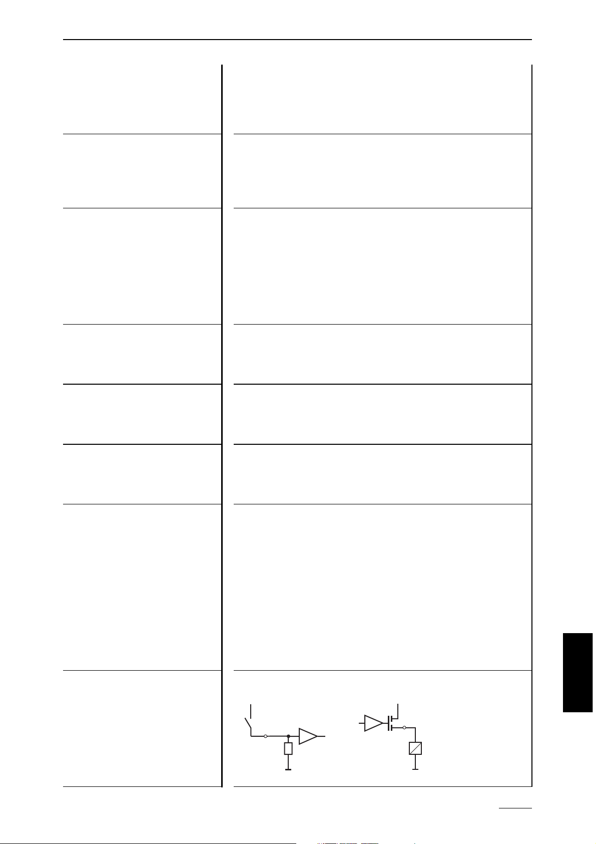
Eingang Low-Side Ausgang High-Side
sensor
+U
B
GND
GND
load
+U
B
Page 8
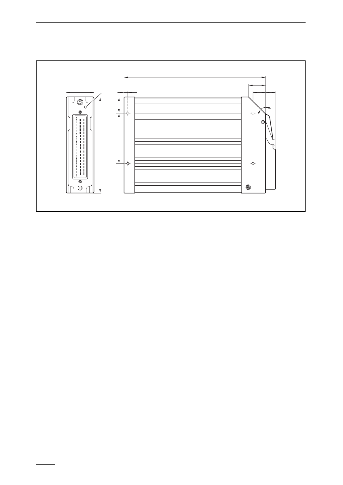
Maßzeichnung
CR0018
Seite 8
43
LED
225
26
205,5
15
153
25,580
45°
Page 9

CR0018
3. Montage
Um die Steuerung ecomat R 360 der geringsten mechanischen Belastung auszusetzen, ist sie vorzugsweise waagerecht liegend oder senkrecht stehend auf
der Montagewand anzubringen. Dazu müssen vier Schrauben nach DIN 7500
bzw. DIN 7984 (M5 x L) benutzt werden.
Wenn möglich sollte die Orientierung der Steuerung so angelegt werden, daß
die Kabeleinführung des Steckers nach unten zeigt.
Da die Eigenerwärmung der Geräteelektronik über das Gehäuse abgeführt
wird, muß bei der „Sandwich-Montage“ von Steuerungen für ausreichende
Kühlung gesorgt werden.
4. Elektrischer Anschluß
Vor der Inbetriebnahme ist zu beachten, daß folgende Anschlüsse mit den
zugehörigen Potentialen belegt werden müssen oder können.
Um den elektrischen Störschutz der Steuerungen ecomat R 360
sicherzustellen, müssen die Gehäuse mit GND (z.B. der Fahrzeugmasse) verbunden werden.
Seite 9
DEUTSCH
Bezeichnung Pin Nr. Potential
Versorgungsspannung
23 (VBBS)
+ 24 V DC
Masse
01 (GNDS)
GND
Versorgungsspannung Ausgänge
High-Side ohne Überwachungsrelais
05 (VBBO)
+ 24 V DC
Versorgungsspannung Ausgänge
High-Side ohne Überwachungsrelais
34 (VBBR)
+ 24 V DC
Versorgungsspannung Ausgänge
Low-Side ohne Überwachungsrelais
15 (GNDO)
GND
Sonderanschlüsse Pin Nr. Potential
Test-Eingang, Programmiermodus 24 (Test) + 24 V DC
Test-Eingang, Betriebsmodus 24 (Test) offen
Schnittstelle RS 232
06 (RxD) Pin 03, PC SUB-D (9 pin)
07 (TxD) Pin 02, PC SUB-D (9 pin)
33 (CM5)
Pin 05, PC SUB-D (9 pin)
CAN-Interface
14 (CANH) CANHweitere Teilnehmer
32 (CANL) CANLweitere Teilnehmer
33 (CM5)
GND weitere Teilnehmer
Page 10

4.1. Absicherung
Zum Schutz des gesamten Systems (Verkabelung und Steuerung) sind die einzelnen Stromkreise entsprechend getrennt abzusichern. Dabei ist auch der
Summenstrom von 10A der einzelnen Ausgangsgruppen (max. 8 Ausgänge z.B. QX0.08...QX0.15) zu beachten.
Wird die Versorgungsspannung der Ausgänge abgetrennt (z.B. VBB
0
Klemme ), müssen die zugehörigen Ein-Ausgangspunkte (Anschlüsse mit
gleichen Pinnummern) auch spannungsfrei geschaltet werden.
5. Betriebszustände
Vor Inbetriebnahme der Steuerung ecomat R 360 muß überprüft werden, ob
sie mit einer Software werksseitig vorgeladen ist. Über die integrierte Diagnose LED kann vom Anwender der Betriebszustand der Steuerung überprüft werden.
Nach Anlegen der Versorgungsspannung kann sich die Steuerungin einem von
5 möglichen Betriebszuständen befinden:
Reset Dieser Zustand wird nach jedem Power-On-Reset durchlaufen.
Das Betriebssystem wird initialisiert. Verschiedene Checks
werden durchgeführt. Dieser nur temporäre Zustand wird vom
Run-Zustand abgelöst.
Die LED leuchtet kurzzeitig orange.
Run Dieser Zustand wird erreicht:
● aus dem Reset-Zustand (Autostart)
● aus dem Stop-Zustand durch das Run-Kommando
Voraussetzung: Test-Betrieb
Die LED blinkt grün oder blinkt rot (RUN mit Fehler)
Stop Dieser Zustand wird erreicht:
● aus dem Reset-Zustand, wenn kein Programm geladen ist
● aus dem Run-Zustand, indem über die Schnittstelle
das Stop-Kommando gegeben wird.
Voraussetzung: Test-Betrieb
Die LED leuchtet konstant grün oder konstant rot
(Stop mit Fehler)
CR0018
Seite 10
Page 11

CR0018
Fatal Error In diesen Zustand fällt die Steuerung, wenn ein nicht tolerier-
barer Fehler festgestellt wurde. Dieser Zustand kann nur durch
einen Reset verlassen werden.
Die LED leuchtet rot.
Kein
Betriebssystem Auslieferungszustand, die Steuerung befindet sich im Bootla-
der. Vor dem Laden der Applikationssoftware muß ein
Betriebssystemdownload durchgeführt werden.
Die LED blinkt grün (schnell).
6. Wartung, Instandsetzung und Entsorgung
Da innerhalb der Steuerung ecomat R 360 keine vom Anwender zu wartenden
Bauteile enthalten sind, darf das Gehäuse nicht geöffnet werden.
Die Instandsetzung der Steuerung darf nur durch den Hersteller durchgeführt
werden.
Die Entsorgung muß gemäß der nationalen Umweltvorschriften erfolgen.
7. Konformitätserklärung
Das CE-Zeichen wird angebracht auf Basis der EMV-Richtlinie EMV
89/336/EWG, realisiert in den Normen EN 500 81-1 und EN 500 82-2 sowie der
Niederspannungsrichtlinie NS73/23/EWG realisiert in der Norm EN61010.
Seite 11
DEUTSCH
Page 12

8. Anhang
Anschlußbelegung CR0018
CR0018
Seite 12
Supply GND
Supply +24 V
Input
GND
12
08
27
09
28
10
29
11
30
44
45
46
47
20
02
21
38
36
54
17
53
19
55
18
37
39
03
40
22
41
42
43
04
48
49
31
50
51
52
16
35
24
%IW9
%IW10
%IW11
%IW12
%IW13
%IW14
%IW15
%IW16
%IX0.08
%IX0.09
%IX0.10
%IX0.11
%IX0.12
%IX0.13
%IX0.14
%IX0.15
%IX0.16
%IX0.17
%IX0.18
%IX0.19
%IX0.20
%IX0.21
%IX0.22
%IX0.23
%IX0.24
%IX0.25
%IX0.26
%IX0.27
%IX0.28
%IX0.29
%IX0.30
%IX0.31
%IX0.32
%IX0.33
%IX0.34
%IX0.35
%IX0.36
%IX0.37
%IX0.38
%IX0.39
Test
A
A
A
A
A
A
A
A
A
BL
BL
BL
BL
IL
IL
IL
IL
BL
BL
BL
BL
IL
IL
IL
IL
BL
BL
BL
BL
BL
BL
BL
BL
BL
BL
BL
BL
BL
BL
BL
BL
BL
0 ... 10 V DC
10 Bit, 50 kΩ
FRQ 0 / ENC 0
FRQ 1 / ENC 0
FRQ 2 / ENC 1
FRQ 3 / ENC 1
CYL 0 / ENC 2
CYL 1 / ENC 2
CYL 2 / ENC 3
CYL 3 / ENC 3
S
S
S
S
S
S
S
S
S
S
S
S
S
S
S
S
S
S
S
S
S
S
S
S
S
S
S
S
S
S
S
S
S
S
S
S
S
S
S
S
S
S
VBB
23
S
VBB
01
GND
S
GND
S
Supply
34
05
CM1CM2CM
R
VBB0VBB
Relais
15
0
GND
4
B/PH
B/PH
B/PH
B/PH
BH
BH
BH
BH
BH
BH
BH
%QX0.00
%QX0.01B/PH
%QX0.02B/PH
%QX0.03B/PH
%QX0.04B/PH
%QX0.05
%QX0.06
%QX0.07
%QX0.08BH
%QX0.09
%QX0.10
%QX0.11
%QX0.12
%QX0.13
%QX0.14
%QX0.15
%QX0.16BH
%QX0.17BH
%QX0.18BH
%QX0.19BH
%QX0.20BH
%QX0.21BH
%QX0.22BH
%QX0.23BH
44
45
46
47
36
54
17
53
39
03
40
22
41
42
43
04
48
49
31
50
51
52
16
35
Output
L
L
L
L
L
L
L
L
L
L
L
L
L
L
L
L
L
L
L
L
L
L
L
L
Output +24 V
Output +24 V
Output GND
PWM 0
PWM 1
PWM 2
PWM 3
PWM 4
PWM 5
PWM 6
PWM 7
Interface
Error
13
06
RxD
07
TxD
CAN
14
H
CAN
32
L
33
CM
5
BH
L
Page 13

CR0018
In der Anschlußbelegung verwendete Abkürzungen
A = analog
BH = binär high-side
BL = binär low-side
CAN
H
= CAN-Schnittstelle
CAN
L
= CAN-Schnittstelle
CYL = Eingang für Periodendauermessung
ENC = Eingang für Drehgebersignale
FRQ = Eingang für Frequenzmessung
IH = Impuls high-side
IL = Impuls low-side
L = Last
PH = PWM high-side
PL = PWM low-side
PWM = Ausgang für Puls-weiten-modulierte Signale
R= Rücklesekanal
RxD = serielle Schnittstelle (Empfangsdaten)
S = Sensor
TxD = serielle Schnittstelle (Sendedaten)
%IWx = IEC-Adresse für analogen Eingang
%IX0.xx = IEC-Adresse für binären Eingang
%QX0.xx = IEC-Adresse für binären Ausgang
Seite 13
DEUTSCH
Page 14

1. General
1.1. Safety instructions
This description is part of the unit. It contains texts and drawings
concerning the correct handling of the controller and must be
read before installation or use.
Observe the information of the description. Non-observance of the notes, operation which is not in accordance with use as prescribed below, wrong installation or handling can result in serious harm concerning the safety of persons
and plant.
The instructions are for authorised persons according to the EMC and low voltage guidelines. The controllers must be installed and commissioned by a skilled electrician (programmer or service technician).
If the unit is not supplied by the mobile on-board system (24V battery operation) it must be ensured that the external voltage is generated and supplied
according to the criteria for safety extra-low voltage (SELV) as this is supplied
without further measures to the connected controller, the sensors, and the
actuators.
The wiring of all signals in connection with the SELV circuit of the unit must also
comply with the SELV criteria (safe extra-low voltage, safe electrical separation
from other electric circuits).
If the supplied SELV voltage has an external connection to ground (SELV becomes PELV) the responsibility lies with the user and the respective national regulations for installation must be complied with. All statements in these operating instructions refer to the unit the SELV voltage of which is not grounded.
The terminals may only be supplied with the signals indicated in the technical
data or on the unit label and only the approved accessories of ifm electronic
gmbh may be connected.
The unit can be operated within a wide temperature range according to the
technical specification indicated below. Due to the additional self-heating the
housing walls can have high perceptible temperatures when touched in hot
environments.
CR0018
page 14
Page 15

CR0018
In case of malfunctions or uncertainties please contact the manufacturer. Tampering with the unit can lead to considerable risks for the safety of persons and
plant. It is not permitted and leads to the exclusion of any liability and warranty claims.
1. 2. Function and features
The controllers ecomat 100 series R 360 (in the following text ecomat R 360)
are for the use under harsh operating conditions (e.g. extended temperature
range, strong vibration, intensive EMC interference). They are thus suited for
direct mounting into machines in mobile and rugged applications. Due to their
specification the inputs and outputs are especially rated for this use. Integrated
hardware and software functions (operating system) offer high protection of
the machine.
The controller ecomat R 360 is not approved for safety-relevant
tasks in the field of safety of persons.
1. 3. Programming
The application software can be easily created by the user with the ifm programming system "ecolog 100 plus" according to IEC 61131-3.
In addition to the programming system the complete system manual is
required to program the controller.
If this manual is not available, please contact one of the ifm branch offices
overleaf for your free copy. The system manual (pdf format) can also be
downloaded from the web (www.ifm-electronic.com).
➔ System manual R 360; English (order no. EC2041)
➔ Data sheet direct ➔ CR0018 ➔ Additional data
The user is responsible for the safe functioning of the application programs which he creates himself. If necessary, he must
additionally obtain an approval according to the corresponding
national regulations by the corresponding testing and supervisory organisations.
Internet
Request
page 15
ENGLISH
Page 16

2. Technical data
CR0018
page 16
Housing
Housing dimension
Mounting position
Connection of the unit
Operating temperature
Storage temperature
Protection rating
Protection class
Air humidity
Supply voltage
Power consumption
Processor
Display
Device monitoring
Memory
Interface
closed, screened metal housingwith flange fastening
225 x 153 x 43mm (WxHxD), without connector
240 x 153 x 43mm (WxHxD), with connector
preferably vertical, alternatively horizontal
55-pin connector, latched, protected against reverse
polarity AMP-type housing with crimp connection
contacts AMP junior timer 0.5/2.5mm
2
-40°C ... +85°C
-40°C ... +90°C
IP 67
(protection for connector, depending on cable version)
III
≤ 90% rel. air humidity, not condensing
(perm. height 2000m)
U
B
nominal 24V DC (-10% ... +25%)
Residual ripple: ≤ 1.5Vpp, f ≤ 50Hz
Reset in case of undervoltage: ≤ +12,0V
Overvoltage: ≤ +36.0V for t ≤ 10s
approx. 10VA, without external load
CMOS-microcontroller C 167 C
three-colour LED red/green/orange for indication of
status and error
8-bit microcontroller to monitor the C 167 C
(extended watchdog function)
undervoltage and overvoltage monitoring
check sum test for program and systemexcess
temperature monitoring
256 kByte program memory
64 kByte data memory
256 Byte auto-Save data memory (protected against
voltage failure)
Full CAN Bus, version 2.0 (ISO/DIS-11898)
Baud rate: 10kBit/s ... 1MBit/s
Device class: CANopen: master/slave
CAN: Full CAN
Serial interface RS 232 C, 9.6kBaud
No. of participants: 2
Page 17

CR0018
ENGLISH
page 17
Binary Input low-side
Inputs
IX0.08 ... IX0.39
Analog input
Inputs IW9 ... IW16
Binary output high-side
Outputs QX0.00...QX0.23
Outputs QX0.00...QX0.07
Input test
Output error
Relay output
Input/output types
switch-on level 0.6 UB... 0,8 UB; I ≥ 6.7mA
switch-off level 0.4 U
B
... 0,2 UB; I ≤ 1.7mA
input frequency 50Hz
50kHz for pulse inputs
input voltage 0 ... 10V
input impedance ≥ 50kΩ
resolution 10 bits
accuracy ≤ ± 1.0% FS
semiconductor output; short-circuit and overload
protected, diagnostic function possible
switching voltage 11 ... 32V
switching current 50mA...2.5A
overload current 5A
total current 10A (for 8 outputs)
output frequency max. 100Hz
(depending on the load)
special specification as PWM output
output frequency max. 1000Hz
PWM pulse ratio 1 ... 99%
resolution depends on the PWM frequency
During the test mode (e.g. programming) the test pin
must be connected to U
B
.
For the "RUN" mode the input must remain
unconnected.
semiconductor output; short-circuit and overload
protected
switching voltage 11 ... 32V
switching current 10mA ... 100mA
overload current 0.5A
internal relay output
normally open contact in series with (max.12) semiconductor outputs for electrically isolated switch-off.
Permanent forced hardware control and additional
control by user program (for further information see
hardware description chapter 2.)
The relay should on principle be switched without
load.
switching current 100mA ... 15A
overload current 20A
number of operating cycles (without load) ≥ 10
6
switching time constant ≤ 3ms
input low-side output high-side
GND
load
+U
B
sensor
+U
B
GND
Page 18

Scale drawing
CR0018
page 18
43
LED
225
26
205,5
15
153
25,580
45°
Page 19

CR0018
3. Mounting
In order to expose the controller to the minimum mechanical stress it should
preferably be mounted horizontally or vertically on the mounting panel. The
module must be fixed with four screws to DIN 7500 or DIN 7984 (M5 x L).
If possible, the controller should be mounted in such a way that the cable entry
of the plug points downwards.
As the self-heating of the electronics of the unit is dissipated via the housing,
sufficient cooling must be ensured in case of "sandwich-mounting" of controllers.
4. Electrical connection
Before commissioning it must be ensured that the following pins must/can be
connected to the corresponding potentials.
To guarantee the electrical interference protection of the controllers ecomat R 360, the housings must be connected to GND
(e.g. to the ground of the vehicle).
page 19
ENGLISH
Designation Pin No. Potential
Supply voltage
23 (VBBS)
+ 24 V DC
Ground
01 (GNDS)
GND
Supply voltage outputs
High-side without monitoring relay
05 (VBBO)
+ 24 V DC
Supply voltage outputs
High-side without monitoring relay
34 (VBBR)
+ 24 V DC
Supply voltage outputs
Low-side without monitoring relay
15 (GNDO)
GND
Special connections Pin No. Potential
Test input, programming mode 24 (test) + 24 V DC
Test input, operating mode 24 (test) open
Interface RS 232
06 (RxD) Pin 03, PC SUB-D (9 pin)
07 (TxD) Pin 02, PC SUB-D (9 pin)
33 (CM5)
Pin 05, PC SUB-D (9 pin)
CAN interface
14 (CANH) CANHfurther participants
32 (CANL) CANLfurther participants
33 (CM5)
GND further participants
Page 20

4.1. Fusing
In order to protect the whole system (cabling and controller) the individual circuits must be fused accordingly, taking into account the total current of 10A of
the individual output modules (max. 8 outputs - e.g. QX0.08 ... QX0.15).
If the supply voltage of the outputs is disconnected (e.g. VBB
0
terminal)
the power of the corresponding input and output points (connections
with the same pin numbers) must also be disconnected.
5. Operating modes
Before commissioning the controller it must be checked to see if software has
been loaded into the controller at the factory. The user can check the operating status of the controller via the integrated diagnostic LED.
When the supply voltage is applied, the controller may be in one of 5 possible
operating modes:
Reset This status is run through after each power-on reset. The
operating system is initialized. Different checks are carried out.
This status is only temporary and is superseded by the run status.
The LED is lit orange for a short time.
Run This status is reached:
● from the reset status (autostart)
● from the stop status by means of the run command
Prerequisite: test mode
The LED flashes green or red (RUN with error)
Stop This status is reached:
● from the reset status, if no program is loaded
● from the run status by giving the stop command via
the interface
Prerequisite: test mode
The LED is constantly lit green or constantly lit red (stop with
error)
CR0018
page 20
Page 21

CR0018
Fatal error The controller passes into this status if a non-tolerable error is
found. This status can only be left via a reset.
The LED is lit red.
No
operating
system Status when delivered, the controller is in the bootloading
status. Before loading the application software a download of
the operating system must be carried out.
The LED flashes green (fast).
6. Maintenance, repair and disposal
As the controller ecomat R 360 does not contain any components which must
be maintained by the user, the housing must not be opened.
The maintenance of the controller may only be carried out by the manufacturer.
The disposal must be carried out according to the corresponding national environmental regulations.
7. Declaration of conformity
The CE-marking is applied on the basis of the EMC guideline EMC
89/336/EWG, implemented in the standards EN 500 81-1 and EN 500 82-2 as
well as the low voltage guideline NS73/23/EWG, implemented in the standard
EN61010.
page 21
ENGLISH
Page 22

8. Annex
Pin connection CR0018
CR0018
page 22
Supply GND
Supply +24 V
Input
GND
12
0 ... 10 V DC
10 Bit, 50 kΩ
FRQ 0 / ENC 0
FRQ 1 / ENC 0
FRQ 2 / ENC 1
FRQ 3 / ENC 1
CYL 0 / ENC 2
CYL 1 / ENC 2
CYL 2 / ENC 3
CYL 3 / ENC 3
S
S
S
S
S
S
S
S
S
S
S
S
S
S
S
S
S
S
S
S
S
S
S
S
S
S
S
S
S
S
S
S
S
S
S
S
S
S
S
S
S
08
27
09
28
10
29
11
30
44
45
46
47
20
02
21
38
36
54
17
53
19
55
18
37
39
03
40
22
41
42
43
04
48
49
31
50
51
52
16
35
24
%IW9
%IW10
%IW11
%IW12
%IW13
%IW14
%IW15
%IW16
%IX0.08
%IX0.09
%IX0.10
%IX0.11
%IX0.12
%IX0.13
%IX0.14
%IX0.15
%IX0.16
%IX0.17
%IX0.18
%IX0.19
%IX0.20
%IX0.21
%IX0.22
%IX0.23
%IX0.24
%IX0.25
%IX0.26
%IX0.27
%IX0.28
%IX0.29
%IX0.30
%IX0.31
%IX0.32
%IX0.33
%IX0.34
%IX0.35
%IX0.36
%IX0.37
%IX0.38
%IX0.39
Test
Supply
Output +24 V
Output +24 V
Output GND
23
01
S
S
VBB
GND
S
S
VBB
GND
A
A
VBB0VBB
A
A
A
A
A
A
A
BL
BL
BL
BL
IL
IL
IL
IL
BL
BL
BL
BL
IL
IL
IL
IL
BL
BL
BL
BL
BL
BL
BL
BL
BL
BL
BL
BL
BL
BL
BL
BL
BL
15
34
05
4
CM1CM2CM
R
0
GND
Relais
B/PH
B/PH
B/PH
B/PH
BH
BH
BH
BH
BH
BH
BH
%QX0.00
%QX0.01B/PH
%QX0.02B/PH
%QX0.03B/PH
%QX0.04B/PH
%QX0.05
%QX0.06
%QX0.07
%QX0.08BH
%QX0.09
%QX0.10
%QX0.11
%QX0.12
%QX0.13
%QX0.14
%QX0.15
%QX0.16BH
%QX0.17BH
%QX0.18BH
%QX0.19BH
%QX0.20BH
%QX0.21BH
%QX0.22BH
%QX0.23BH
44
45
46
47
36
54
17
53
39
03
40
22
41
42
43
04
48
49
31
50
51
52
16
35
Output
L
L
L
L
L
L
L
L
L
L
L
L
L
L
L
L
L
L
L
L
L
L
L
L
PWM 0
PWM 1
PWM 2
PWM 3
PWM 4
PWM 5
PWM 6
PWM 7
Interface
Error
13
06
RxD
07
TxD
CAN
14
H
CAN
32
L
33
CM
5
BH
L
Page 23

CR0018
Abbreviations used in the pin connection diagramm
A = analog
BH = binary high-side
BL = binary low-side
CAN
H
= CAN interface
CAN
L
= CAN interface
CYL = input for time period measurement
ENC = input for encoder signals
FRQ = input for frequency measurement
IH = pulse high-side
IL = pulse low-side
L = load
PH = PWM high-side
PL = PWM low-side
PWM = output for pulse-width-modulated signals
R = readback channel
RxD = serial interface (data received)
S = sensor
TxD = serial interface (data transmitted)
%IWx = IEC address for analog input
%IX0.xx = IEC address for binary input
%QX0.xx = IEC address for binary output
page 23
ENGLISH
Page 24

Technische Änderungen behalten wir uns ohne vorherige Ankündigung vor. Papier chlorfrei gebleicht
 Loading...