

IFM Electronic AX460 Operating Instructions Manual

Operating instructions
Multifunction displays
for analogue standard signals
AX460
80257643 / 00 03 / 2017
UK

Operating instructions AX460
2
Contents
1 Preliminary note � � � � � � � � � � � � � � � � � � � � � � � � � � � � � � � � � � � � � � � � � � � � � � � � � 4
1�1 Symbols used� � � � � � � � � � � � � � � � � � � � � � � � � � � � � � � � � � � � � � � � � � � � � � � 4
1�2 Warnings used � � � � � � � � � � � � � � � � � � � � � � � � � � � � � � � � � � � � � � � � � � � � � � 4
2 Safety instructions � � � � � � � � � � � � � � � � � � � � � � � � � � � � � � � � � � � � � � � � � � � � � � � 5
2�1 General safety instructions� � � � � � � � � � � � � � � � � � � � � � � � � � � � � � � � � � � � � 5
3 Functions and features � � � � � � � � � � � � � � � � � � � � � � � � � � � � � � � � � � � � � � � � � � � � 5
3�1 Product characteristics: � � � � � � � � � � � � � � � � � � � � � � � � � � � � � � � � � � � � � � � 6
4 Installation� � � � � � � � � � � � � � � � � � � � � � � � � � � � � � � � � � � � � � � � � � � � � � � � � � � � � � 6
5 General� � � � � � � � � � � � � � � � � � � � � � � � � � � � � � � � � � � � � � � � � � � � � � � � � � � � � � � � 7
5�1 Operating mode � � � � � � � � � � � � � � � � � � � � � � � � � � � � � � � � � � � � � � � � � � � � � 7
6 Dimensions and mounting � � � � � � � � � � � � � � � � � � � � � � � � � � � � � � � � � � � � � � � � � 8
7 Electrical connection� � � � � � � � � � � � � � � � � � � � � � � � � � � � � � � � � � � � � � � � � � � � � � 8
7�1 DC voltage supply � � � � � � � � � � � � � � � � � � � � � � � � � � � � � � � � � � � � � � � � � � � 9
7�2 Auxiliary voltage output � � � � � � � � � � � � � � � � � � � � � � � � � � � � � � � � � � � � � � � 9
7�3 Analogue inputs � � � � � � � � � � � � � � � � � � � � � � � � � � � � � � � � � � � � � � � � � � � � � 9
7�4 Control inputs � � � � � � � � � � � � � � � � � � � � � � � � � � � � � � � � � � � � � � � � � � � � � � 10
7�5 Reference output � � � � � � � � � � � � � � � � � � � � � � � � � � � � � � � � � � � � � � � � � � � 10
7�6 Control outputs (DX2042, DX2052) � � � � � � � � � � � � � � � � � � � � � � � � � � � � � �11
7�7 AC voltage supply (DX2041, DX2042) � � � � � � � � � � � � � � � � � � � � � � � � � � � �11
8 Operation / touch screen � � � � � � � � � � � � � � � � � � � � � � � � � � � � � � � � � � � � � � � � � 12
8�1 Display for parameter setting � � � � � � � � � � � � � � � � � � � � � � � � � � � � � � � � � � 12
8�2 Display during operation� � � � � � � � � � � � � � � � � � � � � � � � � � � � � � � � � � � � � � 13
9 Parameter / menu overview � � � � � � � � � � � � � � � � � � � � � � � � � � � � � � � � � � � � � � � 14
9�1 Overview � � � � � � � � � � � � � � � � � � � � � � � � � � � � � � � � � � � � � � � � � � � � � � � � � 14
9�2 General Menu� � � � � � � � � � � � � � � � � � � � � � � � � � � � � � � � � � � � � � � � � � � � � � 16
9�3 IN 1 Properties � � � � � � � � � � � � � � � � � � � � � � � � � � � � � � � � � � � � � � � � � � � � � 17
9�4 IN 1 Linearization � � � � � � � � � � � � � � � � � � � � � � � � � � � � � � � � � � � � � � � � � � � 19
9�5 IN 1 Totalization � � � � � � � � � � � � � � � � � � � � � � � � � � � � � � � � � � � � � � � � � � � � 20
9�6 IN 2 Properties � � � � � � � � � � � � � � � � � � � � � � � � � � � � � � � � � � � � � � � � � � � � � 21
9�7 IN 2 Linearization � � � � � � � � � � � � � � � � � � � � � � � � � � � � � � � � � � � � � � � � � � � 22
9�8 IN 2 Totalization � � � � � � � � � � � � � � � � � � � � � � � � � � � � � � � � � � � � � � � � � � � � 22
9�9 Linkage Properties � � � � � � � � � � � � � � � � � � � � � � � � � � � � � � � � � � � � � � � � � � 22
9�10 Preselection values � � � � � � � � � � � � � � � � � � � � � � � � � � � � � � � � � � � � � � � � 23
9�11 Preselection 1 Menu � � � � � � � � � � � � � � � � � � � � � � � � � � � � � � � � � � � � � � � � 24
9�12 Preselection 2 Menu� � � � � � � � � � � � � � � � � � � � � � � � � � � � � � � � � � � � � � � � 26
9�13 Preselection 3 Menu� � � � � � � � � � � � � � � � � � � � � � � � � � � � � � � � � � � � � � � � 27
9�14 Preselection 4 Menu� � � � � � � � � � � � � � � � � � � � � � � � � � � � � � � � � � � � � � � � 28
9�15 Command menu� � � � � � � � � � � � � � � � � � � � � � � � � � � � � � � � � � � � � � � � � � � 29
9�16 Display menu � � � � � � � � � � � � � � � � � � � � � � � � � � � � � � � � � � � � � � � � � � � � � 31
10 linearisation� � � � � � � � � � � � � � � � � � � � � � � � � � � � � � � � � � � � � � � � � � � � � � � � � � � 32

UK
Operating instructions AX460
3
11 Technical data� � � � � � � � � � � � � � � � � � � � � � � � � � � � � � � � � � � � � � � � � � � � � � � � � 35
12 Maintenance, repair and disposal� � � � � � � � � � � � � � � � � � � � � � � � � � � � � � � � � � 36
12�1 Maintenance� � � � � � � � � � � � � � � � � � � � � � � � � � � � � � � � � � � � � � � � � � � � � � 36
12�2 Cleaning the housing surface� � � � � � � � � � � � � � � � � � � � � � � � � � � � � � � � � 36
12�3 Repair� � � � � � � � � � � � � � � � � � � � � � � � � � � � � � � � � � � � � � � � � � � � � � � � � � � 36
12�4 Disposal � � � � � � � � � � � � � � � � � � � � � � � � � � � � � � � � � � � � � � � � � � � � � � � � � 36
13 Approvals/standards � � � � � � � � � � � � � � � � � � � � � � � � � � � � � � � � � � � � � � � � � � � � 36
Licences and trademarks
All trademarks and company names used are subject to the copyright of the respective companies�
Operating instructions AX460
4
1 Preliminary note
This document applies to devices of the type "AX460"�
These instructions are part of the device�
This document is intended for specialists� These specialists are people who are
qualified by their appropriate training and their experience to see risks and to
avoid possible hazards that may be caused during operation or maintenance of
the device� The document contains information about the correct handling of the
device�
Read this document before use to familiarise yourself with operating conditions,
installation and operation� Keep this document during the entire duration of use of
the device�
Adhere to the safety instructions�
1.1 Symbols used
► Instructions
> Reaction, result
[…] Designation of keys, buttons or indications
→ Cross-reference
Important note
Non-compliance may result in malfunction or interference�
Information
Supplementary note
1.2 Warnings used
WARNING
Warning of serious personal injury�
Death or serious irreversible injuries may result�
CAUTION
Warning of personal injury�
Slight reversible injuries may result�
NOTE
Warning of damage to property�

UK
Operating instructions AX460
5
2 Safety instructions
2.1 General safety instructions
This description is an essential part of the device and contains important
information concerning installation, function and operation� Non-compliance may
result in damage or can affect the safety of operators and installations!
Using this device description requires appropriately qualified staff� The device may
only be installed, configured, set up and maintained by a qualified and trained
electrician�
Exclusion of liability: The manufacturer is not liable for any personal injuries or
damage to property that may be caused by improper installation, set-up, operation
and maintenance or by human misinterpretation or mistakes in this device
description� Moreover, the manufacturer reserves the right to change technical
aspects of the device or the description at any time; also without prior notice�
Therefore, possible deviations between the device and the descriptions cannot be
excluded�
The builder of the installation or the entire system is responsible for the safety of
the installation or the entire system in which the system is to be integrated�
During installation, operation and maintenance works, all general and countryspecific as well as application-specific safety regulations and standards must be
observed and respected�
If the device is used in processes where human error or operating errors may
cause damage to the installation or injuries to persons, corresponding measures
must be taken to ensure reliable prevention of such consequences�
3 Functions and features
This device must only be used in industrial machines and installations� Other uses
do not comply with the regulations and are the sole responsibility of the user�
The manufacturer is not liable for damage caused by improper use� The device
must only be installed in compliance with the instructions and only be used and
operated in a perfect technical condition that is in accordance with the technical
data� The device is neither suited for explosion-protected areas nor for areas that
are excluded in DIN EN 61010-1�

Operating instructions AX460
6
3.1 Product characteristics:
● Multifunction device with operating modes for display of input 1 and input 2 and
for linking of input 1 + input 2, input 1 - input 2, input 1 x input 2, input 1 : input
2
● 2 universal 16-bit analogue inputs for -10 ��� 10 V / 0 ��� 20 mA / 4 ��� 20 mA
● Reference output 10 V for potentiometer 1 ≥ kohms
● 7-segment display with symbols and units
● Parameter setting via clear text and touch screen
● Auxiliary voltage output 24 VDC for sensor supply
● Totaliser for each input
● Linearisation with 24 data points per input
● Functions such as tare, averaging, sampling intervals per input
● Standardised 96 x 48 mm housing for panel mounting and protection rating
IP65 (front)
4 Installation
The device may only be installed and operated in an environment that is in
accordance with the permissible temperature range� Provide sufficient ventilation
and avoid direct contact of the unit with hot or aggressive gases or fluids�
Before installation and maintenance works, the unit must be disconnected from all
voltage sources� Also ensure that contact with disconnected voltage supply wires
is prevented�
Devices that are supplied via AC may only be connected via switches or circuit
breakers to the low voltage supply system� This switch must be positioned close to
the device and clearly marked as disconnecting device�
Ingoing and outgoing cables for extra-low voltage must be separated from
dangerous live cables (SELV circuits) by double or reinforced insulation�
The choice of all cables and their insulation must guarantee that they comply with
the permissible voltage and temperature range� Moreover, both device and country
specific standards are to be observed that apply to the cables with regard to their
structure, shape and quality� Please view the technical data for specifications
concerning permissible wire cross-sections for the screw terminal connections�
Before set-up, all connections and cables must be checked if they are tightly fitted
in the screw terminals� All (even unused) screw terminals must be turned to the
right up to the end stop and thereby reliably attached, so that they cannot get
loose due to shocks and vibration�

UK
Operating instructions AX460
7
Voltage spikes on the connections of the device are to be limited to the values of
overvoltage category II�
With regard to installation conditions, wiring, environmental conditions as well as
screening and grounding of connected cables, the general standards for control
cabinet construction in the machine industry as well as the manufacturer's specific
screening instructions apply�
5 General
The device is designed as panel-mounting display unit for analogue signals
(-10 ��� 10 V / 0 ��� 20 mA / 4 ��� 20 mA)�
5.1 Operating mode
In general, all functions can be configured in the parameter menu� The device can
be operated in the following modes:
● SINGLE:
One-channel operation of input 1�
● DUAL:
Two-channel operation of inputs 1 and 2�
● IN 1 + IN 2:
Two-channel operation of inputs 1 and 2, type of linking: addition�
● IN 1 - IN 2:
Two-channel operation of inputs 1 and 2, type of linking: subtraction�
● IN 1 x IN 2:
Two-channel operation of inputs 1 and 2, type of linking: multiplication�
● IN 1 / IN 2:
Two-channel operation of inputs 1 and 2, type of linking: division�

Operating instructions AX460
8
6 Dimensions and mounting
Original Scale Drawing (MTD)
P_MZ_e200_0088
48
96 116
112
► Make a panel cut-out (91 x 43 mm) and fix the device into the panel with the 2
screws�
7 Electrical connection
Original Wiring Drawing (MTD)
AN_i_AX460_GG
1 2 3 4 5 6 7 8 9 10
GND
115 - 230 V AC
0 V AC
GND
18...30 V DC
Aux. Out
AGND
Input 1
Ref. Out
Input 2
GND
Ctr. In 1
11 12 13 14 15 16 17 18 19 20
21 22 23
Ctr. In 2
Ctr. In 3
Com +
Ctr. Out 1
Ctr. Out 2
Ctr. Out 3
Ctr. Out 4
DX2042 / DX2052
24 25 26 27 28 29 30 31 32 33
34 35 36 37 38 39
series DX204x
NC
NC
Connections on the rear of the housing
NOTE
Important: The terminals 16, 17 and 18 must not be used�
UK
Operating instructions AX460
9
7.1 DC voltage supply
The device can be supplied with direct voltage between 18 and 30 V DC via the
terminals 1 and 2� The current consumption depends, among other things, on the
level of the supply voltage and the setting and is typically at approx� 100 mA plus
the sensor current consumed at the auxiliary voltage output�
All GND connections are internally connected with each other�
7.2 Auxiliary voltage output
Auxiliary voltage for sensor supply is provided at terminals 3 and 4�
The output voltage depends on the device supply:
● In case of DC device supply, the output voltage is approx� 1 V less than the
supply voltage applied at terminals 1 and 2 and the max� load must not exceed
250 mA�
● In case of AC device supply, the output voltage is 24 VDC (± 15%) and the
max� load must not exceed 150 mA at temperatures up to 45 °C� At higher
temperatures the max� output current is reduced to 80 mA�
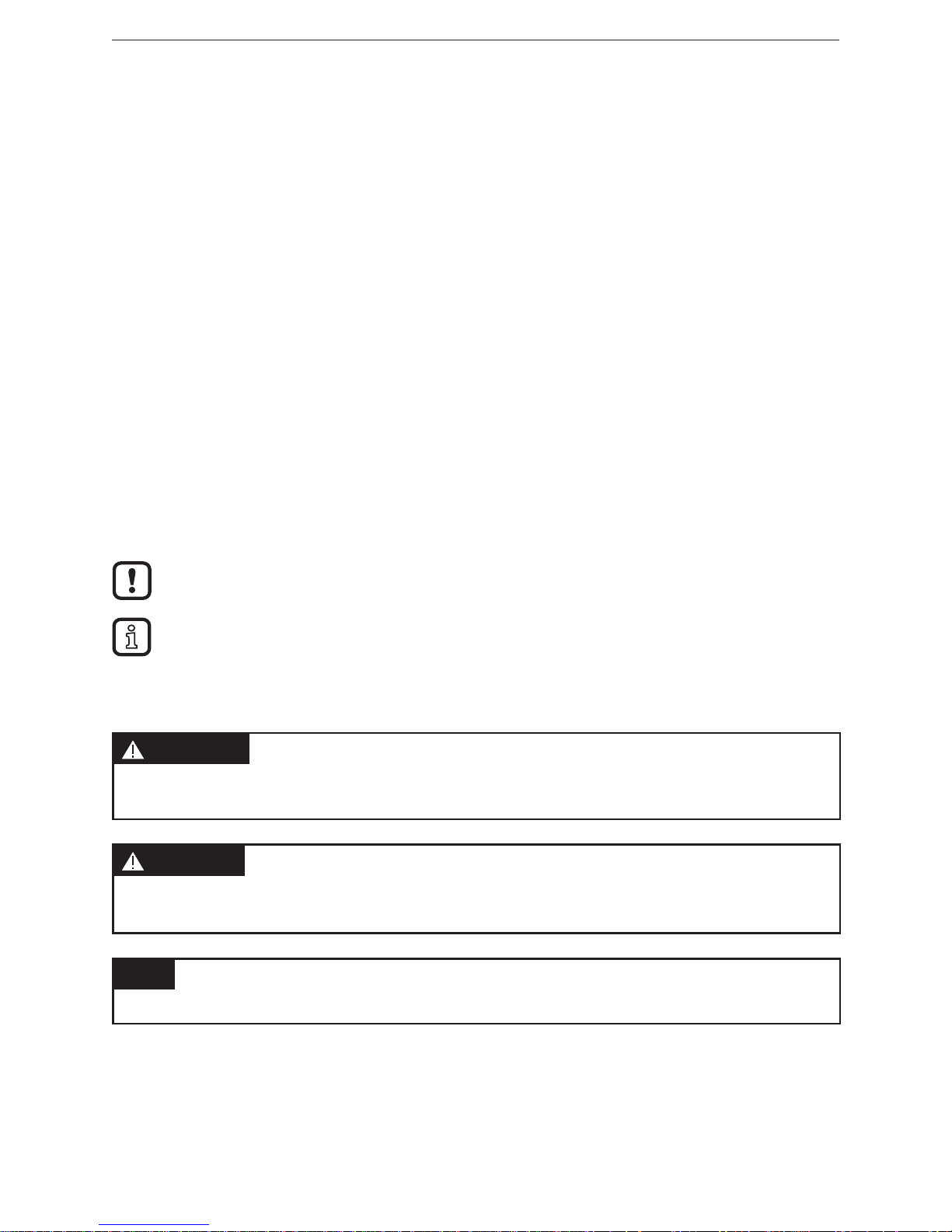
7.3 Analogue inputs
On terminal 5, the reference potential (AGND) for the analogue inputs is
connected� On terminals 6 and 7, two 16 bit analogue outputs are available� The
configuration (voltage input or current input) is set in the IN 1 / IN 2 Properties
menus�
NOTE
Important: The configuration (voltage input or current input) has to be set before
connecting the sensor�
Connection of the analogue inputs:
Voltage input Current input

Operating instructions AX460
10
7.4 Control inputs
On terminals 10, 11 and 12, three control inputs with HTL-PNP characteristic are
available�
These inputs can be configured in the COMMAND MENU and are used for
functions that can be triggered externally such as resetting the display value,
changing the display, locking buttons of the touch screen or releasing the latching
of control outputs�
Connection of the control inputs
Open control inputs are generally "LOW"�
The input stages are designed for electronic control signals�
Remark on mechanical switching contacts:
If mechanical contacts are to be used as pulse source, a standard, external
capacitor of about 10 μF must be connected to the terminals between GND (-) and
the corresponding input (+)� This damps the maximum input frequency to approx�
20 Hz and contact bouncing is suppressed�
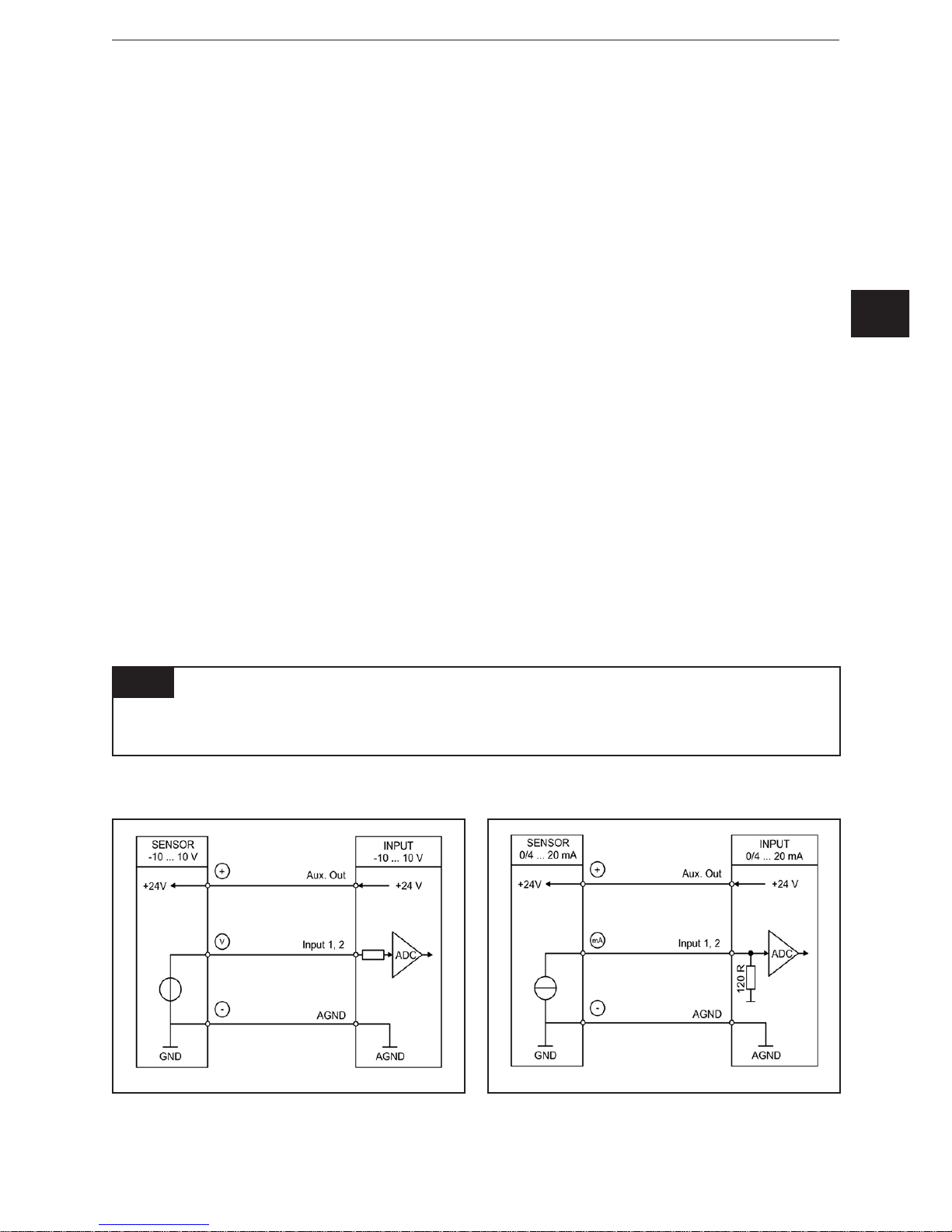
7.5 Reference output
On terminal 8, a 10 V reference output is available� The max� load of this output
must not exceed 10 mA� This reference output can, for example, be used to
connect a potentiometer�
UK
Operating instructions AX460
11
Reference output with potentiometer
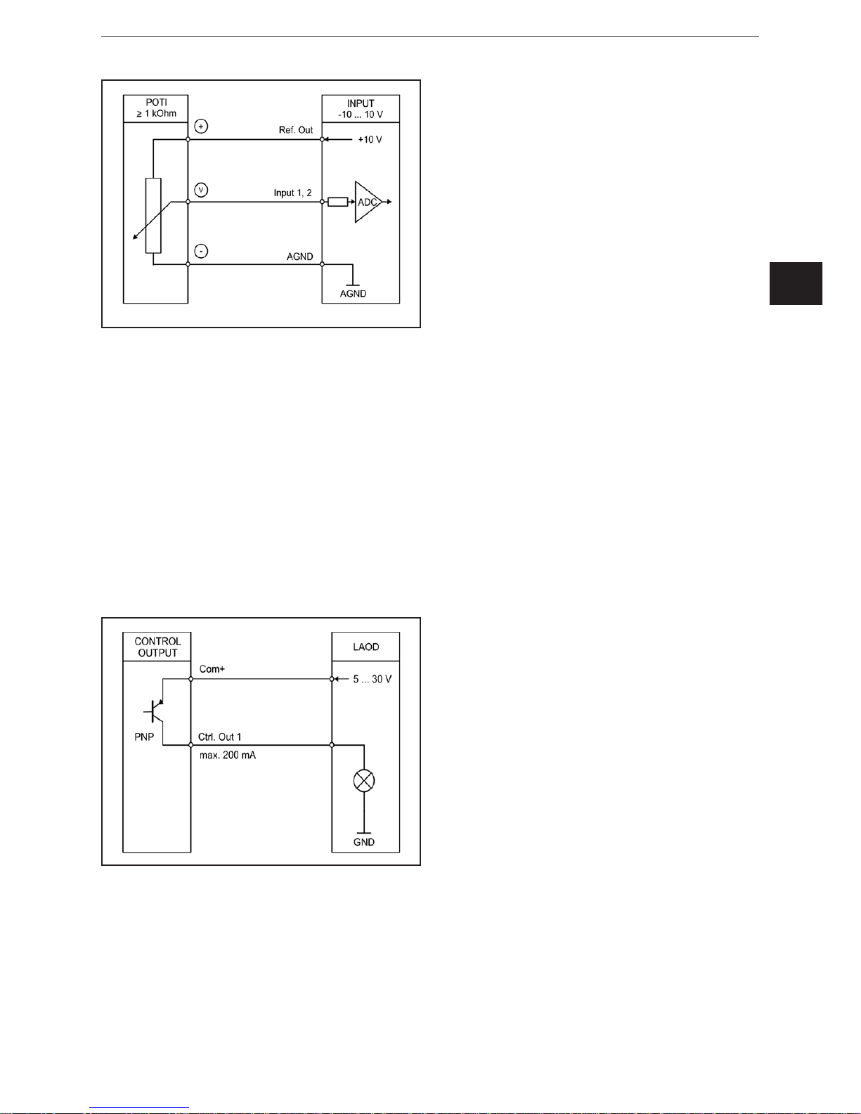
7.6 Control outputs (DX2042, DX2052)
On terminals 20, 21, 22 and 23, four control outputs are available�
The switching conditions can be set in the PRESELECTION MENU�
The outputs Ctrl� Out 1 – Ctrl� Out 4 are fast PNP outputs with a switching capacity
of 5 – 30 V / 200 mA per channel�
The switching voltage is determined by the voltage at terminal 19 (Com+)� To
switch inductive loads, external damping measures are recommended� The
switching status is indicated in the display as C1 – C4 (display with unit and status
line)�
Connection of the control outputs
7.7 AC voltage supply (DX2041, DX2042)
On terminals 24 and 25, the device can be supplied with an alternating voltage
between 115 and 230 V AC� The power consumption depends, among other
things, on the level of the supply voltage and the setting and is at approx� 3 mA
plus the sensor current consumed at the auxiliary voltage output�
 Loading...