

Page 1
Operating instructions
IO-Link master
CabinetLine
AL19xx
80270670/00 10/2017
UK
Page 2

2
1 Preliminary note
Technical data, approvals, accessories and further information at
www.ifm.com.
2 Safety instructions
• Read this document before setting up the product and keep it during the entire
service life.
• The product must be suitable for the corresponding applications and environmental conditions without any restrictions.
• Only use the product for its intended purpose (→ Functions and features).
• If the operating instructions or the technical data are not adhered to, personal
injury and/or damage to property may occur.
• The manufacturer assumes no liability or warranty for any consequences
caused by tampering with the product or incorrect use by the operator.
• Installation, electrical connection, set-up, operation and maintenance of the
product must be carried out by qualified personnel authorised by the machine
operator.
• The plant manufacturer is responsible for the safety of the plant in which the
device is installed.
• If the device is used in a way that is not intended by the manufacturer, the
protection supported by the device may be impaired.
• Protect units and cables against damage.
3 Functions and features
The IO-Link master modules serve as a gateway between intelligent IO-Link
sensors and the field bus. The units with protection rating IP 20 are designed as a
control cabinet module for use in plant construction.
4 Symbols used
►
Instructions
Important note
Non-compliance may result in malfunction or interference.
Page 3
3
UK
4.1 Warnings used
WARNING
Warning of serious personal injury.
Death or serious irreversible injuries may result.
4.2 Safety symbols on the device
General warning on the device.
When this symbol appears, consider the corresponding section in the operating
instructions.
5 Installation
► Disconnect power before installation.
► Mount the unit in a control cabinet with a protection rating of at least IP 54 to
ensure protection against accidental contact with dangerous contact voltages
and against external influence. The control cabinet should be installed in accor-
dance with local and national rules and regulations.
► Mount the unit vertically on a DIN rail.
► Leave enough space between the unit and the top or bottom of the control
cabinet as well as to adjacent devices to enable air circulation and to avoid
inadmissible heating.
5.1 Installation instructions
Electrostatic discharge
The device contains components that can be damaged or destroyed by electrosta-
tic discharge.
► When handling the device, observe the necessary safety precautions against
electrostatic discharge (ESD).
► The device may only be operated when mounted on a grounded DIN rail.
WARNING
► Do not open the devices.
► Do not insert any objects into the devices.
► Prevent foreign bodies made of metal from penetrating.
Page 4
4
6 Electrical connection
The unit must be connected by a qualified electrician.
The national and international regulations for the installation of electrical equipment
must be adhered to.
The communication interfaces are insulated among each other and from the
device supply (according to EN60950-1, basic insulation as secondary circuit max.
30 V DC, SELV).
They are designed for network environment 0 according to IEC TR62102).
► The device may not be used beyond the limits of the technical data.
► Disconnect the installation from power and connect the unit.
6.1 Wiring
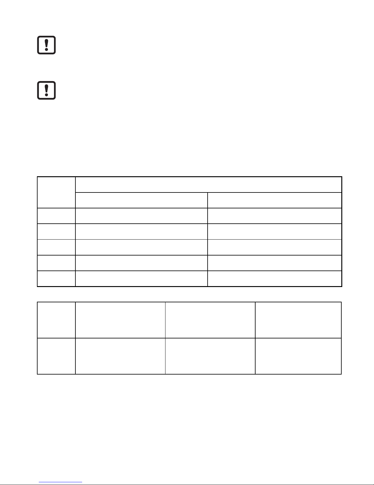
AL1900 / AL1920 / AL1930
IO-Link Voltage supply US
Terminal IO-Link A ports X01...X08 IN X 31
1 + 24 V DC (US) GND (US)
2 DI GND (US)
3 GND (US) + 24 V DC (US)
4 C/Q IO-Link + 24 V DC (US)
RJ45 PROFINET
Ethernet port
X21 / X22
EtherNet/IP
Ethernet port
X21 / X22
EtherCAT
Ethernet port
X21 / X22
RJ45 IoT (Internet of Things)
Ethernet port
X32
IoT (Internet of Things)
Ethernet port
X32
IoT (Internet of Things)
Ethernet port
X32
Page 5
5
UK
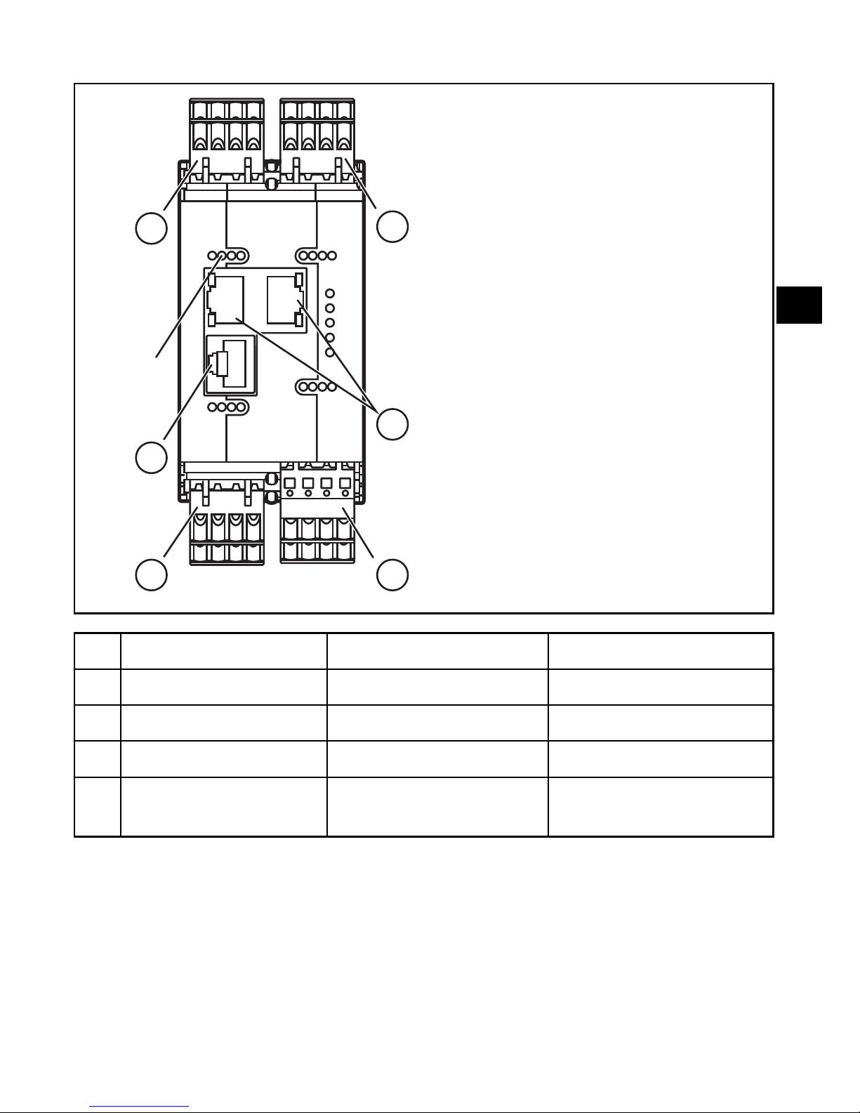
6.2 Interfaces
LEDs
1
2
3
2
2
4
AL1900 AL1920 AL1930
1 Voltage supply Voltage supply Voltage supply
2 8 IO-Link A ports 8 IO-Link A ports 8 IO-Link A ports
3 PROFINET-IO EtherNet/IP EtherCAT
4 IoT port
(Internet of Things)
IoT port
(Internet of Things)
IoT port
(Internet of Things)
Page 6

6
7 Factory settings
AL1900
PROFINET
AL1920
EtherNet/IP
AL19xx
IoT (Internet of Things)
IP address 0.0.0.0 192.168.1.250 169.254.X.X
IP addressing DCP static
IP address
DCP, DHCP, Auto IP
Subnet mask 0.0.0.0 255.255.255.0 255.255.0.0
Gateway IP address 0.0.0.0 0.0.0.0 0.0.0.0
MAC address see type label see type label see type label
8 Parameter setting
The parameter setting and configuration of the field bus interface is done via the
higher-level PLC.
As an option, the connected IO-Link devices can be configured with the ifm software LR DEVICE.
9 Maintenance, repair and disposal
The unit is maintenance-free.
► Disconnect the device.
► Clean the device from dirt using a soft, chemically untreated and dry cloth.
9.1 Disposal
► Dispose of the device in accordance with the applicable national environmental
regulations.
Page 7
7
UK
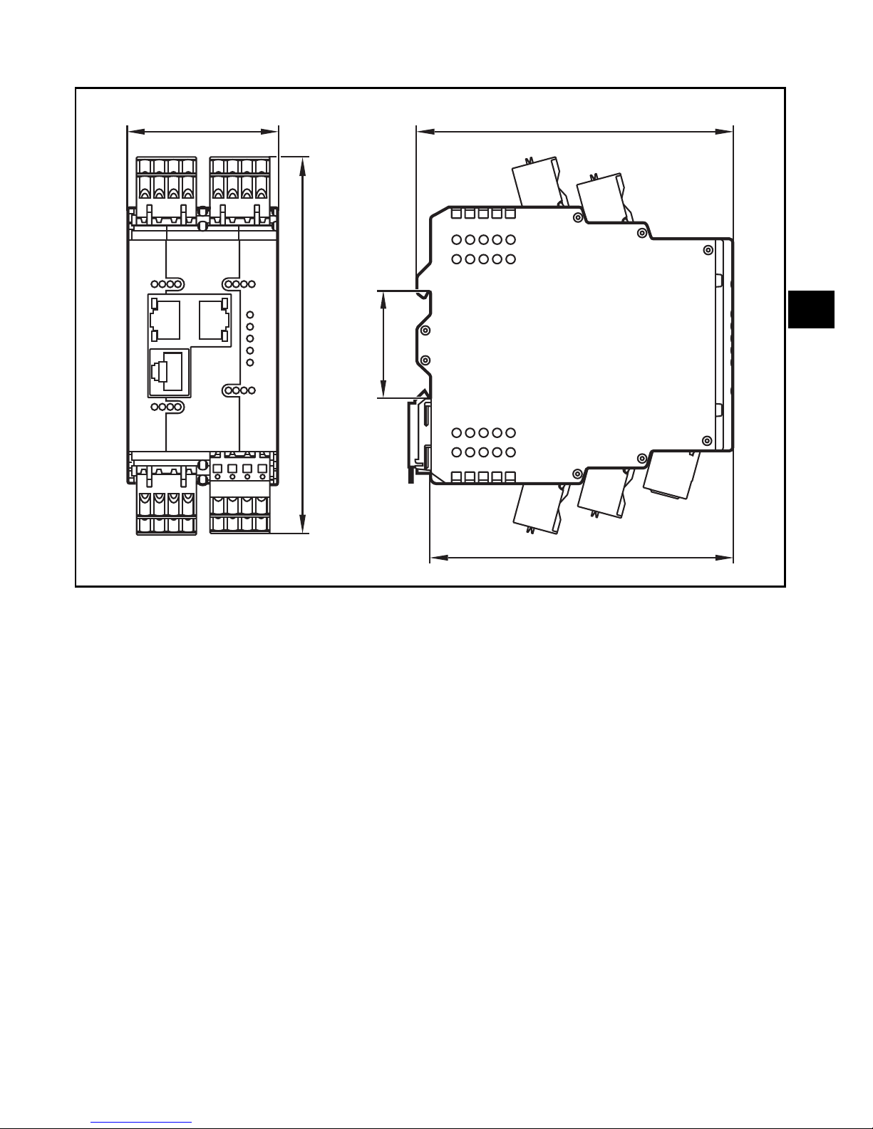
10 Scale drawing
50
125,7
35
105,3
100,6
 Loading...