

IFM Electronic AL1340, AL1940 Operating Instructions Manual

Operating Instructions
IO-Link Master with Modbus TCP interface
DataLine
4 Ports
IP 65 / IP 66 / IP 67
AL1340
IO-Link: 1.1.2
ifm firmware: 2.1.19 or higher
LR DEVICE: 1.3.0.131 or higher
English
7391168 / 00 04 / 2018

ifm Operating Instructions IO-Link Master with Modbus TCP interface DataLine 4 Ports IP 65 / IP 66 / IP 67 (AL1340) 04 / 2018
Content
Table of Contents
1 Preliminary note 5
1.1 Legal and copyright information ........................................................................................... 5
1.2 Purpose of the document ..................................................................................................... 5
1.3 Symbols and styles used ..................................................................................................... 6
1.4 Modification history .............................................................................................................. 6
2 Safety instructions 7
2.1 General ................................................................................................................................ 7
2.2 Required background knowledge ........................................................................................ 7
2.3 Safety symbols on the device .............................................................................................. 8
2.4 Tampering with the unit ........................................................................................................ 8
3 Intended use 9
3.1 Permitted use ....................................................................................................................... 9
3.2 Prohibited use ...................................................................................................................... 9
4 Function 10
4.1 Communication, parameter setting, evaluation .................................................................11
4.1.1 IO-Link ........................................................................................................................................ 11
4.1.2 Modbus TCP .............................................................................................................................. 11
4.1.3 Internet of Things (IoT) ............................................................................................................... 11
4.1.4 Parameter setting ....................................................................................................................... 11
4.1.5 Visual indication ......................................................................................................................... 12
4.2 Digital inputs .......................................................................................................................12
4.3 IO-Link supply ....................................................................................................................12
5 Mounting 13
5.1 Mount the device ................................................................................................................13
6 Electrical connection 14
6.1 Remarks .............................................................................................................................14
6.2 Modbus TCP ports .............................................................................................................15
6.3 IoT port ...............................................................................................................................15
6.4 IO-Link ports .......................................................................................................................16
6.4.1 Input circuit ................................................................................................................................. 17
6.4.2 IO-Link circuits ............................................................................................................................ 17
6.5 Connect the device ............................................................................................................18
7 Operating and display elements 19
7.1 Overview ............................................................................................................................19
7.2 LED indicators ....................................................................................................................20
7.2.1 Status LEDs ............................................................................................................................... 20
7.2.2 Ethernet interface ....................................................................................................................... 21
7.2.3 IoT port ....................................................................................................................................... 21
7.2.4 Voltage supply ............................................................................................................................ 21
7.2.5 IO-Link ports (Class A) ............................................................................................................... 22
2

ifm Operating Instructions IO-Link Master with Modbus TCP interface DataLine 4 Ports IP 65 / IP 66 / IP 67 (AL1340) 04 / 2018
Content
8 Configuration 23
8.1 LR DEVICE ........................................................................................................................24
8.1.1 Remarks ..................................................................................................................................... 25
8.1.2 IoT: Configure access rights ....................................................................................................... 26
8.1.3 IoT: Configure IP settings ........................................................................................................... 27
8.1.4 IoT: Configure the interface to the LR SMARTOBSERVER ....................................................... 28
8.1.5 Fieldbus: configure Modbus TCP port ........................................................................................ 29
8.1.6 IO-Link ports: Activate data transfer to the LR SMARTOBSERVER .......................................... 30
8.1.7 IO-Link ports: Configure operating mode.................................................................................... 31
8.1.8 IO-Link ports: Set the device validation and data storage .......................................................... 32
8.1.9 IO-Link ports: set fail-safe values ............................................................................................... 33
8.1.10 Info: Show device information .................................................................................................... 33
8.1.11 Firmware: Reset device to factory settings ................................................................................. 34
8.1.12 Firmware: Reboot the device ...................................................................................................... 34
8.1.13 Configure IO-Link devices .......................................................................................................... 35
8.2 Modbus TCP ......................................................................................................................36
8.2.1 Integrate the AL1340 into the Modbus project ............................................................................ 36
8.2.2 Set IO-Link master and IO-Link ports ......................................................................................... 38
8.2.3 read input data of several IO-Link ports...................................................................................... 39
8.2.4 Read input data of individual IO-Link ports ................................................................................. 40
8.2.5 Write output data of several IO-Link ports .................................................................................. 41
8.2.6 Write output data of individual IO-Link ports ............................................................................... 42
8.2.7 Read diagnostic information and events..................................................................................... 43
8.2.8 Read device information ................................ ................................................................ ............. 44
8.2.9 Control IO-Link master ............................................................................................................... 44
8.2.10 Configure IO-Link devices .......................................................................................................... 44
8.2.11 Modbus TCP: Programmers' notes ............................................................................................ 45
8.3 IoT Core .............................................................................................................................47
8.3.1 Configure IoT port ...................................................................................................................... 48
8.3.2 Configure the fieldbus port ......................................................................................................... 49
8.3.3 Configure IO-Link ports .............................................................................................................. 49
8.3.4 Set application identification ....................................................................................................... 50
8.3.5 Read / write cyclic process data ................................................................................................. 50
8.3.6 Read diagnostic data .................................................................................................................. 50
8.3.7 Read device information ................................ ................................................................ ............. 51
8.3.8 Read information about IO-Link devices .................................................................................... 51
8.3.9 Configure IO-Link devices .......................................................................................................... 52
8.3.10 Control IO-Link master ............................................................................................................... 52
8.3.11 Examples .................................................................................................................................... 53
8.3.12 Programmers' notes ................................................................................................................... 57
3

ifm Operating Instructions IO-Link Master with Modbus TCP interface DataLine 4 Ports IP 65 / IP 66 / IP 67 (AL1340) 04 / 2018
Content
9 Operation 61
9.1 Identify device ....................................................................................................................61
9.2 Firmware update ................................................................................................................62
9.3 Replace IO-Link device ......................................................................................................63
10 Maintenance 64
11 Factory settings 65
12 Accessories 66
13 Appendix 67
13.1 Technical data ....................................................................................................................68
13.1.1 Application .................................................................................................................................. 68
13.1.2 Electrical data ............................................................................................................................. 68
13.1.3 Inputs / outputs ........................................................................................................................... 68
13.1.4 Inputs.......................................................................................................................................... 69
13.1.5 Outputs ................................................................ ................................................................ ....... 69
13.1.6 Interfaces .................................................................................................................................... 69
13.1.7 Operating conditions .................................................................................................................. 70
13.1.8 Approvals / tests ......................................................................................................................... 70
13.1.9 Mechanical data ......................................................................................................................... 70
13.1.10 Electrical connection .................................................................................................................. 71
13.2 Modbus TCP ......................................................................................................................72
13.2.1 Register ...................................................................................................................................... 73
13.2.2 Acyclic commands ...................................................................................................................... 89
13.3 ifm IoT Core .....................................................................................................................100
13.3.1 Overview: IoT profile ................................................................................................................ 101
13.3.2 Overview: IoT types .................................................................................................................. 104
13.3.3 Overview: IoT services ............................................................................................................. 105
14 Index 117
4

ifm Operating Instructions IO-Link Master with Modbus TCP interface DataLine 4 Ports IP 65 / IP 66 / IP 67 (AL1340) 04 / 2018
Preliminary note Legal and copyright information
1 Preliminary note
Legal and copyright information ............................................................................................................... 5
Purpose of the document ......................................................................................................................... 5
Symbols and styles used .......................................................................................................................... 6
Modification history ................................................................................................................................... 6
>
14801
1.1 Legal and copyright information
1631
© All rights reserved by ifm electronic gmbh. No part of this manual may be reproduced and used
without the consent of ifm electronic gmbh.
All product names, pictures, companies or other brands used on our pages are the property of the
respective rights owners:
AS-i is the property of the AS-International Association, (→ www.as-interface.net)
CAN is the property of the CiA (CAN in Automation e.V.), Germany (→ www.can-cia.org)
CODESYS™ is the property of the 3S – Smart Software Solutions GmbH, Germany
(→ www.codesys.com)
DeviceNet™ is the property of the ODVA™ (Open DeviceNet Vendor Association), USA
(→ www.odva.org)
EtherNet/IP® is the property of the →ODVA™
EtherCAT® is a registered trade mark and patented technology, licensed by Beckhoff Automation
GmbH, Germany
IO-Link® (→ www.io-link.com) is the property of the →PROFIBUS Nutzerorganisation e.V.,
Germany
ISOBUS is the property of the AEF – Agricultural Industry Electronics Foundation e.V.,
Deutschland (→ www.aef-online.org)
Microsoft® is the property of the Microsoft Corporation, USA (→ www.microsoft.com)
PROFIBUS® is the property of the PROFIBUS Nutzerorganisation e.V., Germany
(→ www.profibus.com)
PROFINET® is the property of the →PROFIBUS Nutzerorganisation e.V., Germany
Windows® is the property of the →Microsoft Corporation, USA
>
1.2 Purpose of the document
This document is only for device types "IO-Link master - Modbus TCP gateway (DataLine) 4 port IP 65
/ IP 66 / IP 67" (art. no.: AL1340).
It is part of the device and contains information about the correct handling of the product.
► Read this document before using the device.
► Keep this document during the service life of the device.
22044
5
ifm Operating Instructions IO-Link Master with Modbus TCP interface DataLine 4 Ports IP 65 / IP 66 / IP 67 (AL1340) 04 / 2018
Preliminary note Symbols and styles used
>
WARNING
Death or serious irreversible injuries may result.
CAUTION
Slight reversible injuries may result.
NOTICE
Property damage is to be expected or may result.
Important note
Non-compliance can result in malfunction or interference
Information
Supplementary note
► ...
Request for action
> ...
Reaction, result
→ ...
"see"
abc
Cross-reference
123
0x123
0b010
Decimal number
Hexadecimal number
Binary number
[...]
Designation of pushbuttons, buttons or indications
Version
Topic
Date
00
New creation of document
04 / 2018
1.3 Symbols and styles used
15989
>
1.4 Modification history
6
21676

ifm Operating Instructions IO-Link Master with Modbus TCP interface DataLine 4 Ports IP 65 / IP 66 / IP 67 (AL1340) 04 / 2018
Safety instructions General
2 Safety instructions
General ..................................................................................................................................................... 7
Required background knowledge ............................................................................................................. 7
Safety symbols on the device ................................................................................................................... 8
Tampering with the unit ............................................................................................................................ 8
The plant manufacturer is responsible for the safety of the plant in which the device is
installed.
If the device is used in a way that is not intended by the manufacturer, the protection
supported by the device may be impaired.
Non-observance of the instructions, operation which is not in accordance with use as
prescribed below, wrong installation or incorrect handling can affect the safety of operators
and machinery.
► Observe these operating instructions.
► Adhere to the warning notes on the product.
>
2.1 General
22068
>
2.2 Required background knowledge
22046
This document is intended for specialists. Specialists are people who, based on their relevant training
and experience, are capable of identifying risks and avoiding potential hazards that may be caused
during operation or maintenance of the product.
The document contains information about the correct handling of the product.
213
7

ifm Operating Instructions IO-Link Master with Modbus TCP interface DataLine 4 Ports IP 65 / IP 66 / IP 67 (AL1340) 04 / 2018
Safety instructions Safety symbols on the device
>
General warning
Observe instructions in chapter "Electrical connection" (→ Electrical connection (→ p. 14))!
WARNING
Tampering with the units can affect the safety of operators and machinery!
Tampering with the units is not allowed.
In case of non-compliance our liability and warranty expire.
► Do not open the devices!
► Do not insert any objects into the devices!
► Prevent metal foreign bodies from penetrating!
2.3 Safety symbols on the device
>
2.4 Tampering with the unit
15021
11242
8

ifm Operating Instructions IO-Link Master with Modbus TCP interface DataLine 4 Ports IP 65 / IP 66 / IP 67 (AL1340) 04 / 2018
Intended use Permitted use
3 Intended use
Permitted use ........................................................................................................................................... 9
Prohibited use ........................................................................................................................................... 9
>
3.1 Permitted use
The IO-Link master serves as a gateway between intelligent IO-Link devices and the fieldbus. The
device is designed for use without a control cabinet in the plant construction.
>
3.2 Prohibited use
The device may not be used beyond the limits of the technical data (→ Technical data (→ p. 68))!
18761
22052
22053
9

ifm Operating Instructions IO-Link Master with Modbus TCP interface DataLine 4 Ports IP 65 / IP 66 / IP 67 (AL1340) 04 / 2018
Function Prohibited use
4 Function
Communication, parameter setting, evaluation ......................................................................................11
Digital inputs ...........................................................................................................................................12
IO-Link supply .........................................................................................................................................12
7482
10

ifm Operating Instructions IO-Link Master with Modbus TCP interface DataLine 4 Ports IP 65 / IP 66 / IP 67 (AL1340) 04 / 2018
Function Communication, parameter setting, evaluation
>
IO-Link ....................................................................................................................................................11
Modbus TCP ...........................................................................................................................................11
Internet of Things (IoT) ...........................................................................................................................11
Parameter setting ...................................................................................................................................11
Visual indication ......................................................................................................................................12
4.1 Communication, parameter setting, evaluation
>
7485
4.1.1 IO-Link
7773
The device offers the following IO-Link functions:
IO-Link master (IO-Link revision 1.0 and 1.1)
4 IO-Link ports for connection of IO-Link devices
Provision of process data of the connected IO-Link devices for LR SMARTOBSERVER monitoring
software (→ www.ifm.com)
>
4.1.2 Modbus TCP
2259
The device offers the following Modbus TCP functions:
Provision of the functions of a Modbus TCP Slave
2 port switch for access to the Modbus TCP interface (X21/X22)
Gateway for transmission of the process and parameter data between the connected IO-Link
devices and the higher-level Modbus TCP controller
>
4.1.3 Internet of Things (IoT)
8355
The device has an Ethernet port (X23) for Internet-of-Things applications. The interface allows
separate access from IT networks to parameters, process and monitoring data of the IO-Link master
and the connected IO-Link devices. Different protocols (e.g. TCP/IP JSON) are supported.
>
4.1.4 Parameter setting
The device provides the following configuration options:
Parameter setting of the IO-Link master of the AL1340 with LR DEVICE parameter setting
software, Modbus TCP projection software or ifm IoT-Core services.
Parameter setting of the connected IO-Link devices (sensors, actuators) with LR DEVICE
parameter setting software, Modbus TCP projection software or ifm IoT-Core services
Storage of parameter sets of the connected IO-Link devices for automatic recovery (data storage)
7284
11

ifm Operating Instructions IO-Link Master with Modbus TCP interface DataLine 4 Ports IP 65 / IP 66 / IP 67 (AL1340) 04 / 2018
Function Digital inputs
>
4.1.5 Visual indication
The device has the following visual indicators:
Status and error indication of the gateway, of the Modbus TCP connection and of the system
Status display of the voltage supply
Status and activity display of the Ethernet connection
Status, error and short circuit/overload indication of the IO-Link ports
>
4.2 Digital inputs
The device has 4 additional digital inputs (type 2 according to EN 61131-2).
The digital inputs are on pin 2 of the IO-Link ports X01 ... X04.
All inputs refer to the potential of the device supply (pin 3).
>
4.3 IO-Link supply
The device has 4 supplies for IO-Link devices.
The IO-Link ports X01...X04 are ports class A.
Every supply provides short circuit monitoring.
The device ensures fire protection for the connected IO-Link devices by providing a power-restricted
circuit at the IO-Link ports (according to IEC61010-1 and Class 2 according to UL1310).
7772
7584
7623
12

ifm Operating Instructions IO-Link Master with Modbus TCP interface DataLine 4 Ports IP 65 / IP 66 / IP 67 (AL1340) 04 / 2018
Mounting Mount the device
5 Mounting
Mount the device ....................................................................................................................................13
► Disconnect the system from power before installation.
► For installation choose a flat mounting surface.
► Please observe the maximum tightening torque.
>
5.1 Mount the device
► Fix the unit to the mounting surface using 2 M5 mounting screws and washers.
Tightening torque: 1.8 Nm
► Ground the unit via the two mounting screws of the upper mounting lugs.
22016
15540
13

ifm Operating Instructions IO-Link Master with Modbus TCP interface DataLine 4 Ports IP 65 / IP 66 / IP 67 (AL1340) 04 / 2018
Electrical connection Remarks
6 Electrical connection
Remarks .................................................................................................................................................14
Modbus TCP ports ..................................................................................................................................15
IoT port ...................................................................................................................................................15
IO-Link ports ...........................................................................................................................................16
Connect the device .................................................................................................................................18
A qualified electrician must connect the unit.
► Observe the national and international regulations for the installation of electrical
equipment.
Device is only suitable for operation on SELV/PELV voltages.
► Observe the information concerning IO-Link circuits (→ IO-Link circuits (→ p. 17))!
The device contains components that can be damaged or destroyed by electrostatic discharge
(ESD).
► Observe the required safety measures against electrostatic discharge!
The IP rating depends on the individual protection ratings of the unit, the applied connection
elements and the corresponding protective covers.
► For UL applications: For connecting the device and the IO-Link devices use UL certificated
cables of category CYJV or PVVA with a minimum temperature rating of 100°C.
► Depending on the mounting conditions, cables must be provided with a strain relief to
avoid unacceptable loads on the mounting points and M12 connections.
► Make sure that the M12 connection parts are correctly seated and mounted correctly. The
specified protection rating can not be guaranteed if this is not observed.
Wiring: → Technical data (→ p. 68)
The communication interfaces are seperated from the device supply according to EN61010-1
considering basis isolation as secondary circuit with maximum 30 V DC derived from the
applied voltage up to 300 V of overvoltage category II. The communication interfaces are
designed for a network environment 0 according to IEC TR62102.
>
6.1 Remarks
22017
18076
14
ifm Operating Instructions IO-Link Master with Modbus TCP interface DataLine 4 Ports IP 65 / IP 66 / IP 67 (AL1340) 04 / 2018
Electrical connection Modbus TCP ports
>
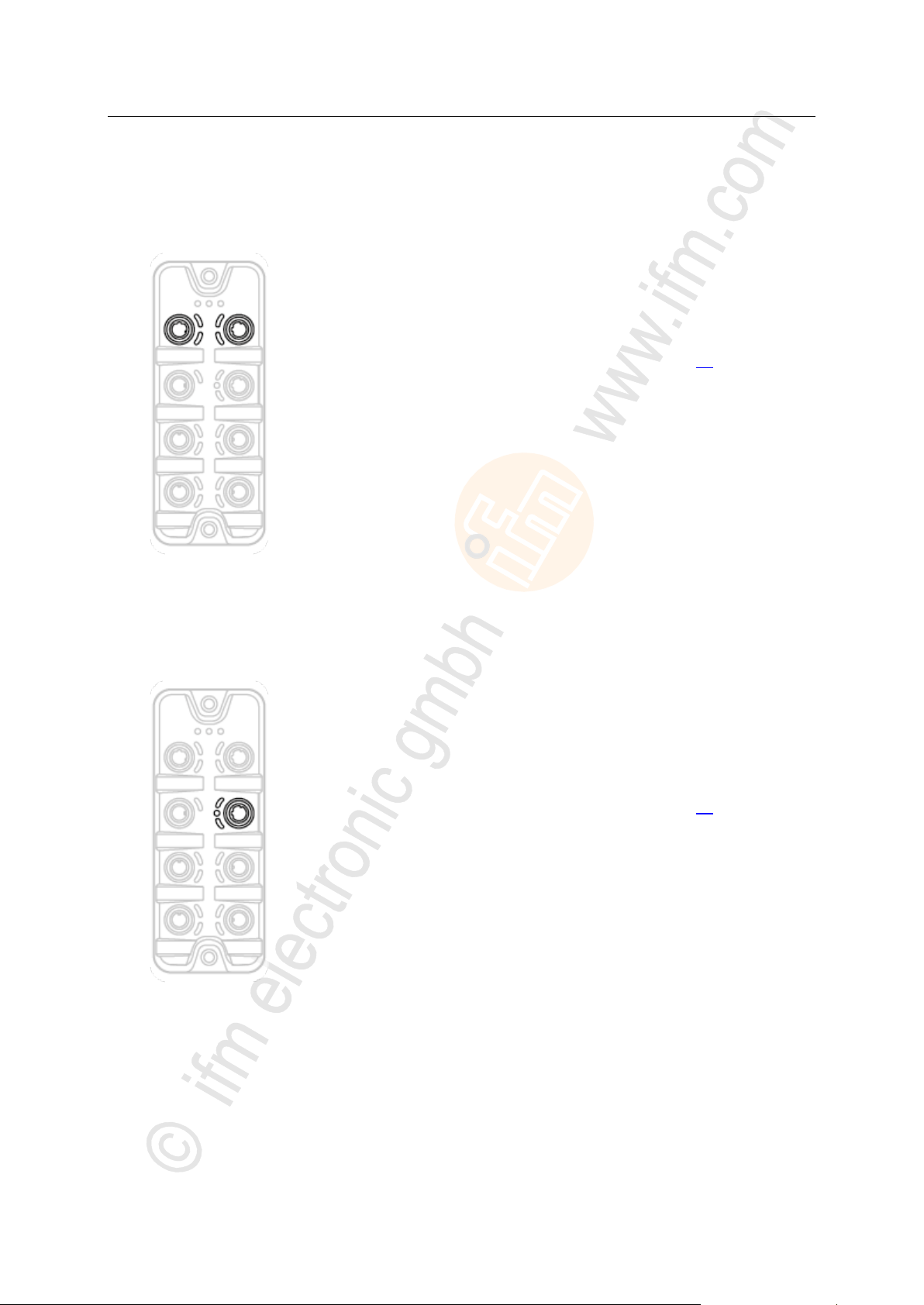
► Connect the device via the M12 socket X21 and/or X22 to the
Modbus TCP network
(e.g. Modbus TCP PLC, additional Modbus TCP device)
Tightening torque: 0.6...0.8 Nm
► To connect the devices, use M12 connectors with protection rating
IP 65 / IP 66 / IP 67 or higher (→ Accessories (→ p. 66)).
► Cover the unused sockets with M12 protective caps (art no.
E73004).
Tightening torque 0.6...0.8 Nm
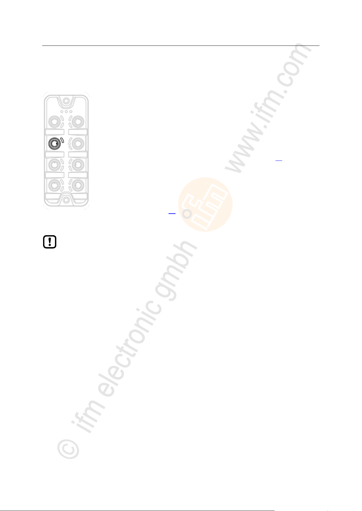
► Connect the device via the M12 socket X23 to the IT network (e.g.
laptop/PC with installed LR DEVICE parameter setting software,
laptop/PC with installed LR SMARTOBSERVER monitoring
software)
Tightening torque: 0.6...0.8 Nm
► To connect the devices, use M12 connectors with protection rating
IP 65 / IP 66 / IP 67 or higher (→ Accessories (→ p. 66)).
► Cover the unused sockets with M12 protective caps (art no.
E73004)
Tightening torque 0.6...0.8 Nm
6.2 Modbus TCP ports
>
17849
6.3 IoT port
11029
15
ifm Operating Instructions IO-Link Master with Modbus TCP interface DataLine 4 Ports IP 65 / IP 66 / IP 67 (AL1340) 04 / 2018
Electrical connection IO-Link ports
>
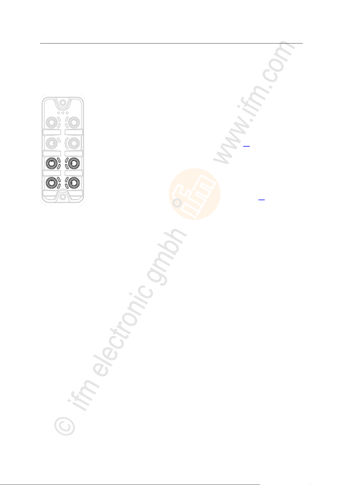
Ports X01...X04: For use as IO-Link port class A:
► Connect the connector of the IO-Link devices with the M12 sockets
X01 ... X04.
Tightening torque: 0.6...0.8 Nm
Maximum cable length per IO-Link interface: 20 m
► For the connection, use M12 connectors with protection rating IP 65
/ IP 66 / IP 67 or higher (→ Accessories (→ p. 66)).
Ports X01...X04: For use as IO-Link port class B:
► Connect the connector of the IO-Link devices via the adapter with
the M12 sockets X01 ... X04.
Tightening torque: 0.6...0.8 Nm
► To connect the devices, use M12 connectors with protection rating
IP 65 / IP 66 / IP 67 or higher (→ Accessories (→ p. 66)).
► Cover the unused sockets with M12 protective caps (art no.
E73004).
Tightening torque 0.6...0.8 Nm
6.4 IO-Link ports
22684
16

ifm Operating Instructions IO-Link Master with Modbus TCP interface DataLine 4 Ports IP 65 / IP 66 / IP 67 (AL1340) 04 / 2018
Electrical connection IO-Link ports
>
The connected IO-Link devices may only be supplied via the AL1340.
Exception: Connection of IO-Link devices to ports X01...X04 via suitable connection
technology for port class B operation (→ IO-Link ports (→ p. 16)):
The external supply for port class B operation must be galvanically separeted from the circuit
of the AL1340 by assuring basic isolation (according to EN61010-1, secondary circuit with
maximum 30 V DC derived from applied voltage up to 300 V of overvoltage category II)!
The isolation must be done both for IO-Link devices and for the connection technology.
NOTICE
Risk of material damage
If the requirements of galvanic separation of the circuits are not observed, the fire protection of the
device can not be assured.
► Observe the requirements of the electrical connection of IO-Link devices for port class B
operation!
6.4.1 Input circuit
18629
The inputs of the ports X01...X04 (pin 2) provide a type 2 behaviour according to standard EN61131-2,
the connected electronics must be rated for this electrically.
>
6.4.2 IO-Link circuits
11616
The IO-Link interfaces of the device meet the requirements of the IO-Link specification 1.0 to 1.1.2.
Further information: → Technical data (→ p. 68)
17
ifm Operating Instructions IO-Link Master with Modbus TCP interface DataLine 4 Ports IP 65 / IP 66 / IP 67 (AL1340) 04 / 2018
Electrical connection Connect the device
>
► Disconnect power.
► Connect the unit via M12 socket X31 to 24 V DC
(20...30 V SELV/PELV, for cULus max. 24 V DC; according to
EN61010-1, secondary circuit with maximum 30 V DC derived from
applied voltage up to 300 V of overvoltage category II).
Tightening torque: 0.6...0.8 Nm
Maximum cable length: 25 m
► To connect the device , use M12 connectors with protection rating
IP 65 / IP 66 / IP 67 or higher (→ Accessories (→ p. 66)).
If the port X01...X04 will be used as IO-Link ports Class B:
► Connect adapter for Port Class B operation to 24 V DC
(20...30 V SELV/PELV, for cULus max. 24 V DC; according to
EN61010-1, secondary circuit with maximum 30 V DC derived from
applied voltage up to 300 V of overvoltage category II) (→ IO-Link
ports (→ p. 16))
Tightening torque: 0.6...0.8 Nm
When using connectors longer than 25 m keep in mind the voltage drop as well as the
required minimum voltage supply of the AL1340.
6.5 Connect the device
2580
18
ifm Operating Instructions IO-Link Master with Modbus TCP interface DataLine 4 Ports IP 65 / IP 66 / IP 67 (AL1340) 04 / 2018
Operating and display elements Overview
7 Operating and display elements
Overview .................................................................................................................................................19
LED indicators ........................................................................................................................................20
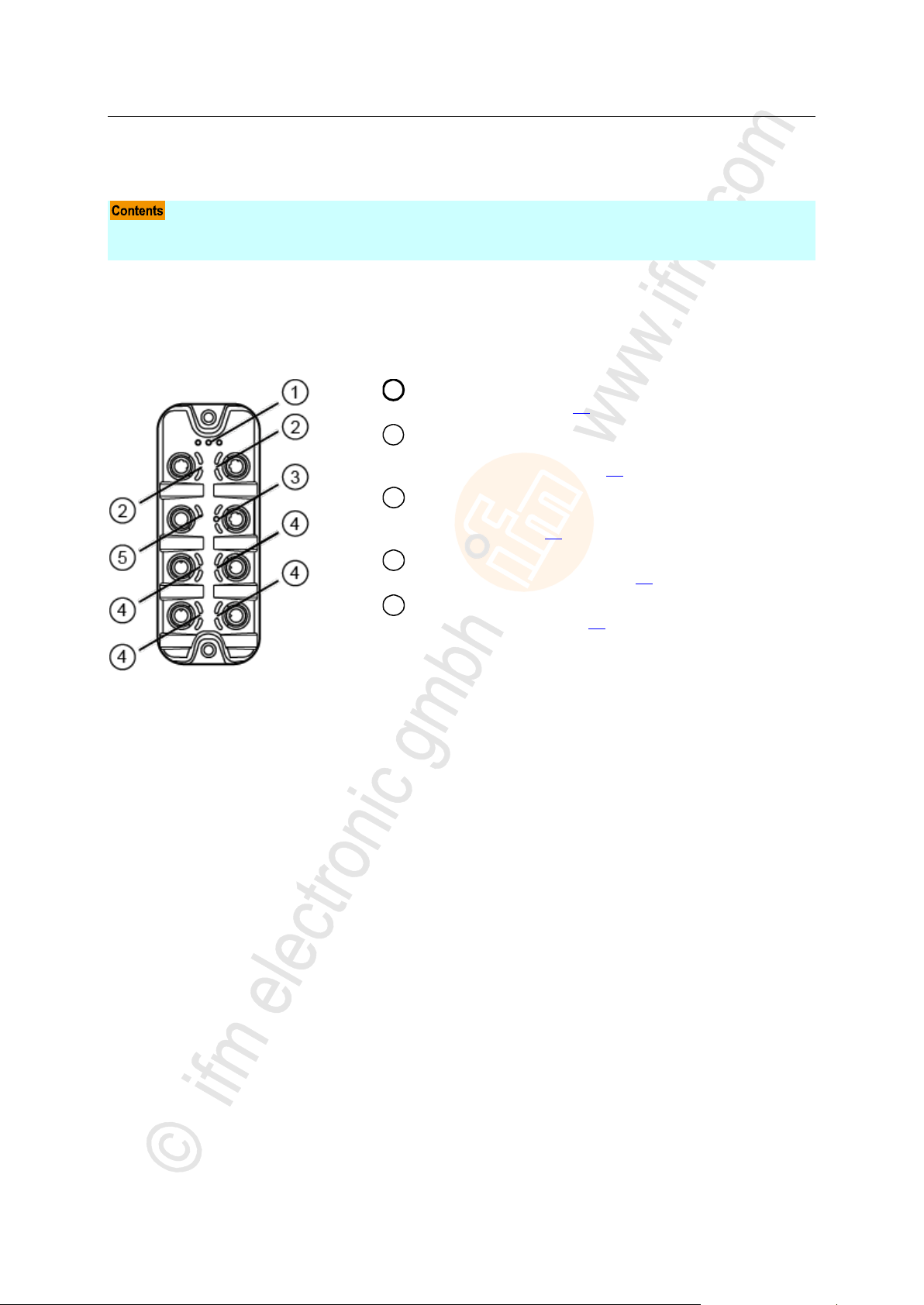
1
RDY, RUN and ERR status LEDs
→ Status LEDs (→ p. 20)
2
LNK and ACT status LEDs of the Modbus TCP
interfaces 1 (X21) and 2 (X22)
→ Ethernet interface (→ p. 21)
3
LNK, ACT status-LEDs and IoT LED of the IoT
interface (X23)
→ IoT port (→ p. 21)
4
IOL and DI status-LEDs of the IO-Link port (X01...X04)
→ IO-Link ports (Class A) (→ p. 22)
5
PWR status LED of the voltage supply (X31)
→ Voltage supply (→ p. 21)
>
7.1 Overview
5440
17857
19

ifm Operating Instructions IO-Link Master with Modbus TCP interface DataLine 4 Ports IP 65 / IP 66 / IP 67 (AL1340) 04 / 2018
Operating and display elements LED indicators
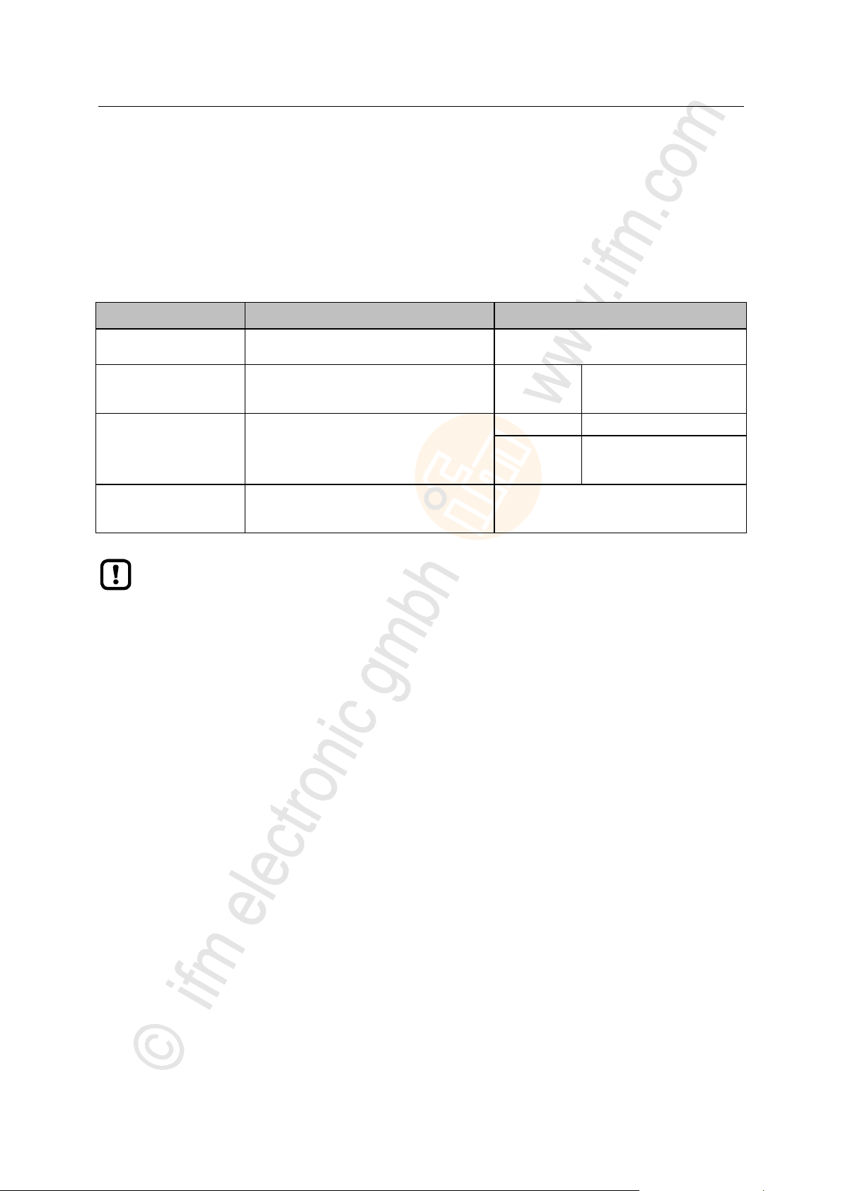
>
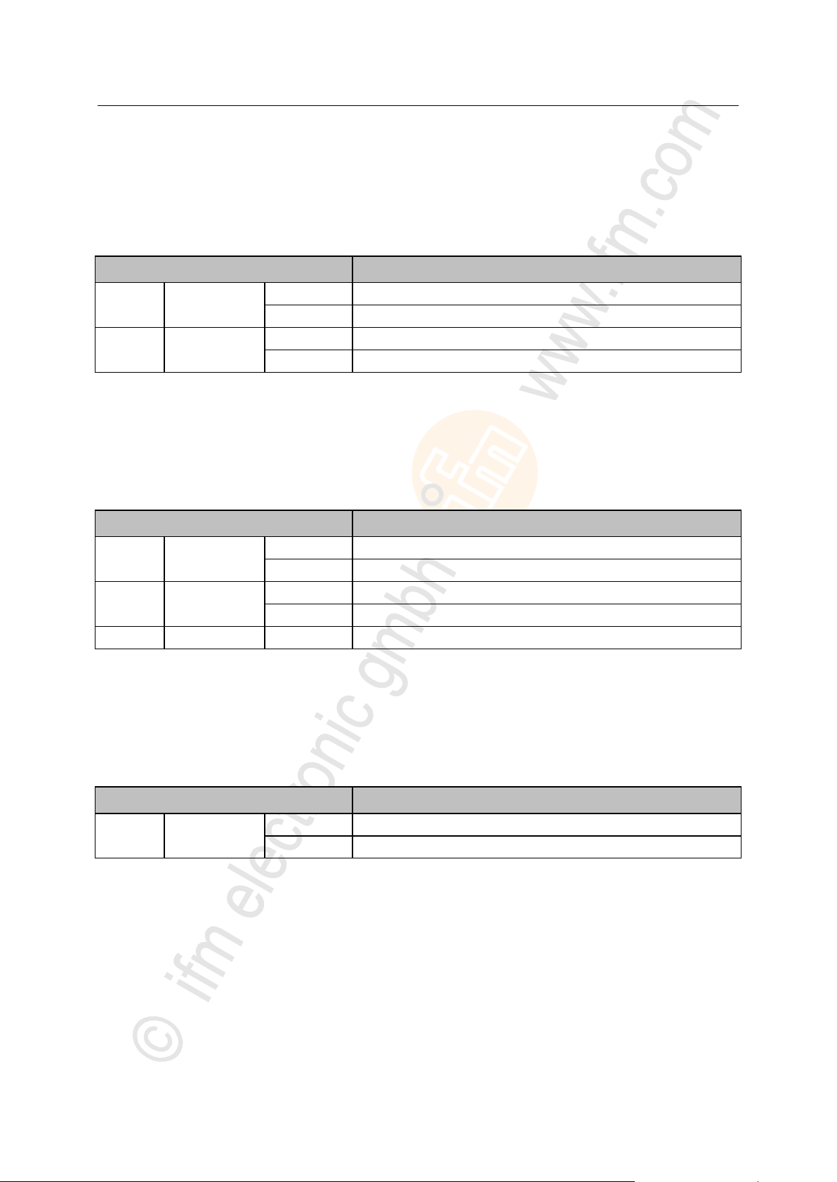
Status LED
Description
RDY
green
on
gateway functions properly
flashing 1 Hz
error
flashing 5 Hz
firmware update
off
gateway does not function; device reboots
ERR
red
on
error in application controller
flashes (10 Hz)
boot error
flashes (200 ms on,
200 ms off, 200 ms on,
1000 ms off)
watchdog error (Modbus TCP or process data)
flashes (200 ms on,
1000 ms off)
local error
flashes (2.5 Hz)
invalid configuration
off
no error
RUN
green
on
connection established
flashes (1 Hz)
ready, but not yet configured
flashes (5 Hz)
waiting for connection
off
not ready
7.2 LED indicators
The device only has the following LED indicators:
>
7.2.1 Status LEDs
The RDY LED indicates the status of the gateway.
The RUN LED indicates the current state of the Modbus TCP state machine.
The ERR LED indicates occurring errors.
22024
11748
20
ifm Operating Instructions IO-Link Master with Modbus TCP interface DataLine 4 Ports IP 65 / IP 66 / IP 67 (AL1340) 04 / 2018
Operating and display elements LED indicators
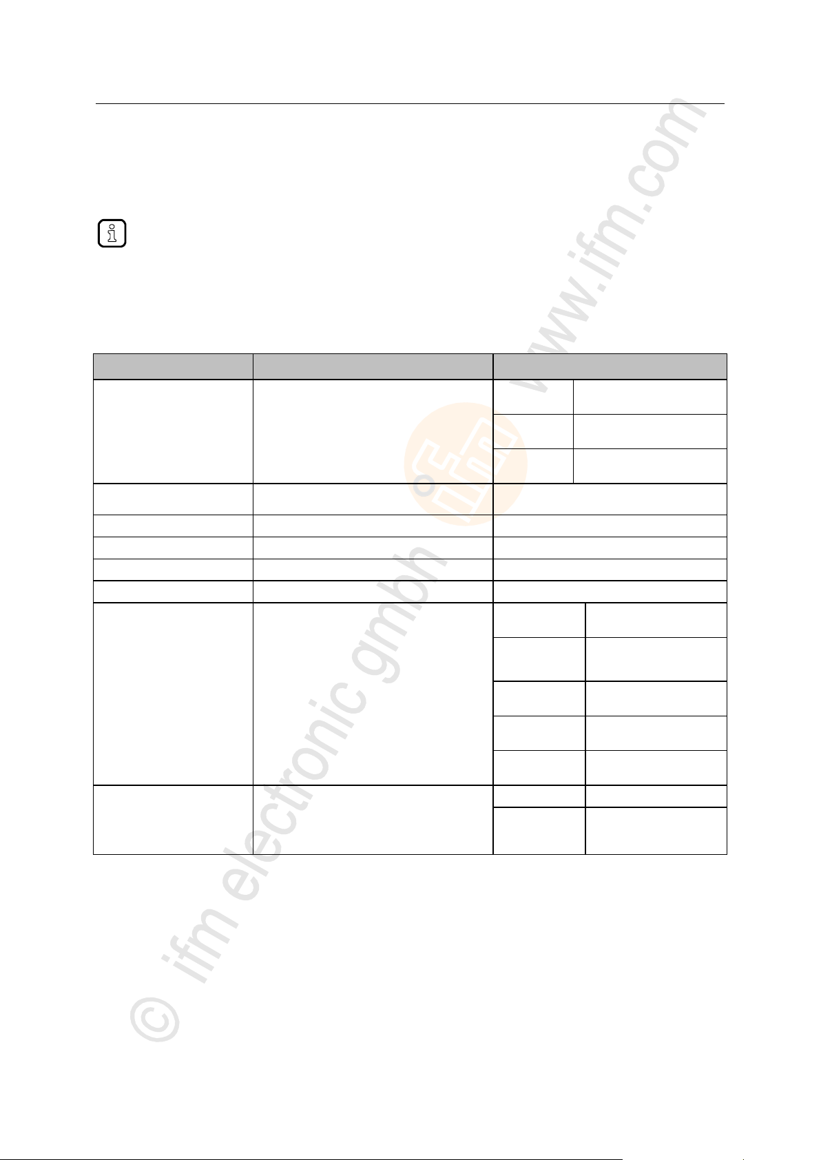
>
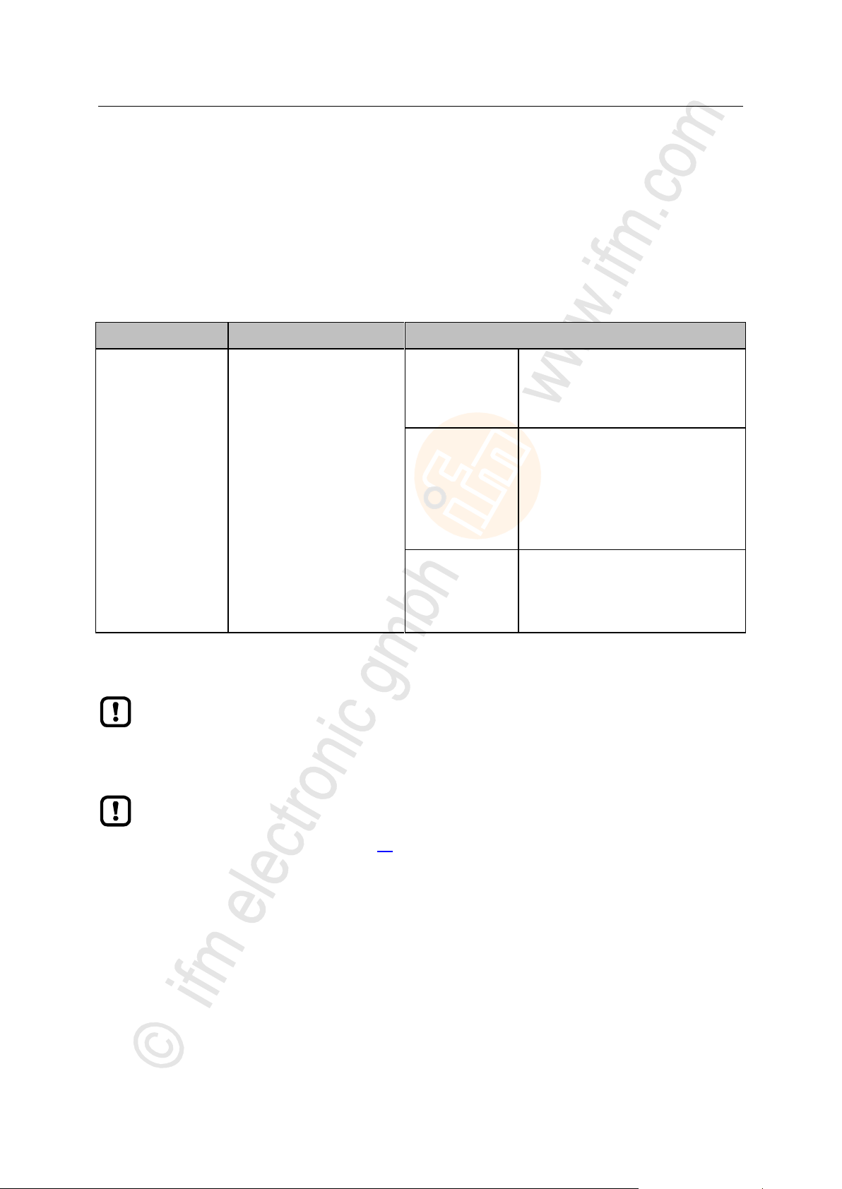
Status LED
Description
LNK
green
on
Ethernet connection established
off
No Ethernet connection
ACT
yellow
flashes
Data is transmitted via the Ethernet interface.
off
No data transmission
Status LED
Description
LNK
green
on
Ethernet connection established
off
No Ethernet connection
ACT
yellow
flashes
Data is transmitted via the Ethernet interface.
off
No data transmission
IoT
green
flashes
Device identification active
Status LED
Description
US
green
on
The supply voltage Us is applied.
off
No supply voltage is applied or the applied supply voltage is too low.
7.2.2 Ethernet interface
Each Ethernet interface (X21, X22) has 2 LEDs (LNK and ACT). The LEDs indicate the status of the
Ethernet connection.
>
7.2.3 IoT port
The IoT port (X23) has the 3 LNK, ACT and IoT LEDs. The LEDs indicate the status of the Ethernet
connection and the device identification.
22027
7722
>
7.2.4 Voltage supply
22026
The interface for voltage supply (X31) has the LED that is marked as US. The LED indicates the status
of the voltage supply.
21

ifm Operating Instructions IO-Link Master with Modbus TCP interface DataLine 4 Ports IP 65 / IP 66 / IP 67 (AL1340) 04 / 2018
Operating and display elements LED indicators
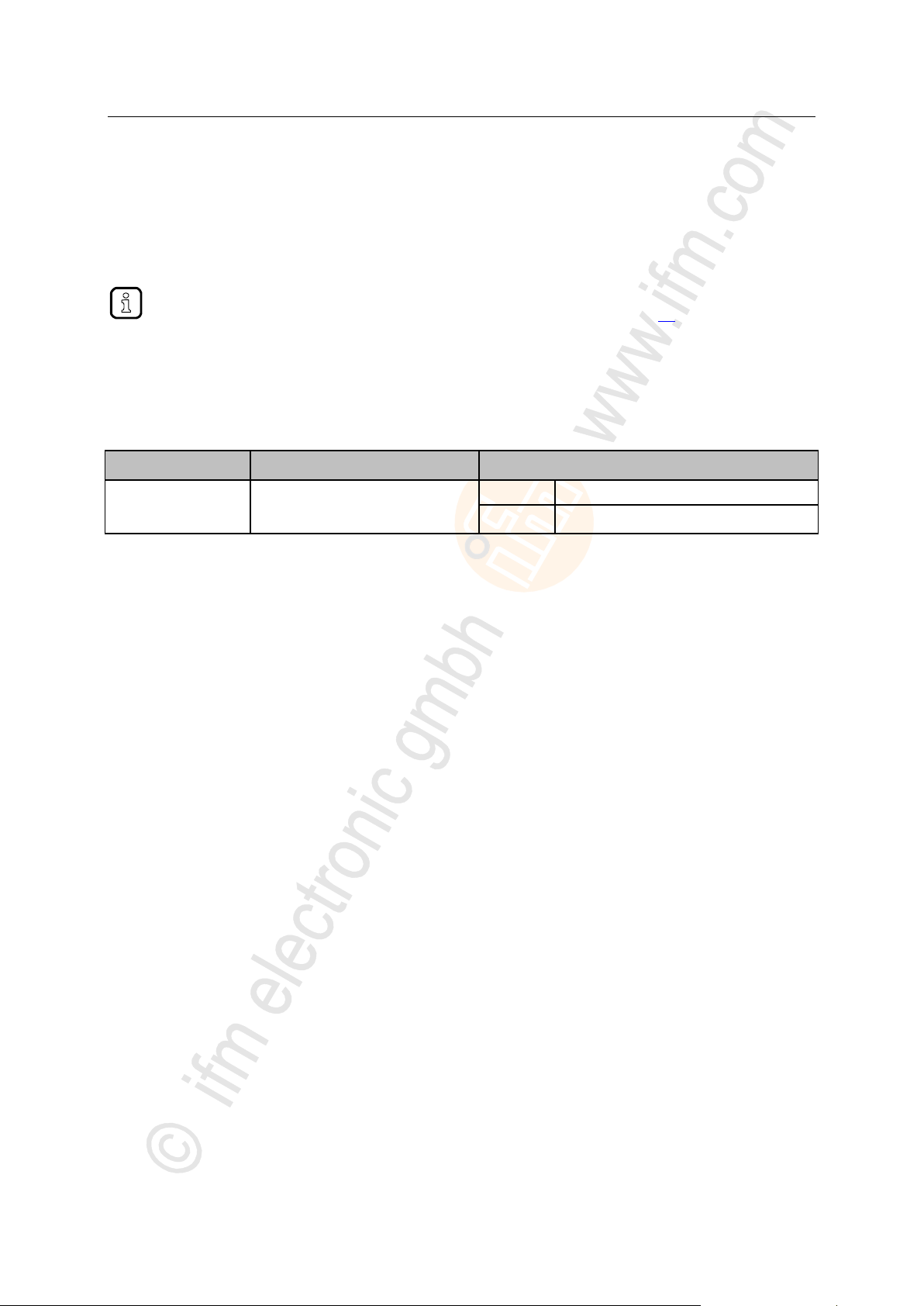
>
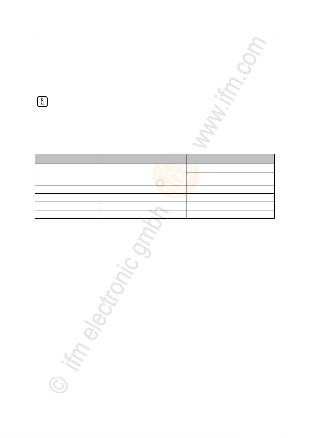
Status LED
Description
IOL
yellow
on
Interface configured as DI/DO: pin 4 (C/Q) =ON
off
Interface configured as DI/DO: pin 4 (C/Q) = OFF
green
on
IO-Link transmission functions properly
flashes 1 Hz
Interface configured as IO-Link, but no IO-Link transmission
red
on
Short circuit or overload in supply voltage
flashes 1 Hz
Transmission error
DI
yellow
on
Digital input: pin 2 (DI) = ON
off
Digital input : pin 2 (DI) = OFF
7.2.5 IO-Link ports (Class A)
Each IO-Link port Class A (X01 ... X04) has 2 LEDs marked as IOL and DI. The LEDs indicate the
status of the IO-Link port.
22029
22

ifm Operating Instructions IO-Link Master with Modbus TCP interface DataLine 4 Ports IP 65 / IP 66 / IP 67 (AL1340) 04 / 2018
Configuration LED indicators
8 Configuration
LR DEVICE .............................................................................................................................................24
Modbus TCP ...........................................................................................................................................36
IoT Core ..................................................................................................................................................47
22367
23

ifm Operating Instructions IO-Link Master with Modbus TCP interface DataLine 4 Ports IP 65 / IP 66 / IP 67 (AL1340) 04 / 2018
Configuration LR DEVICE
>
Remarks .................................................................................................................................................25
IoT: Configure access rights ...................................................................................................................26
IoT: Configure IP settings .......................................................................................................................27
IoT: Configure the interface to the LR SMARTOBSERVER ..................................................................28
Fieldbus: configure Modbus TCP port ....................................................................................................29
IO-Link ports: Activate data transfer to the LR SMARTOBSERVER .....................................................30
IO-Link ports: Configure operating mode ...............................................................................................31
IO-Link ports: Set the device validation and data storage ......................................................................32
IO-Link ports: set fail-safe values ...........................................................................................................33
Info: Show device information ................................................................................................................33
Firmware: Reset device to factory settings ............................................................................................34
Firmware: Reboot the device..................................................................................................................34
Configure IO-Link devices ......................................................................................................................35
8.1 LR DEVICE
On delivery, the AL1340 is configured with the factory settings (→ Factory settings (→ p. 65)).
Required software: LR DEVICE (1.3.0.131 or higher) (art.-no.: QA0011/QA0012)
22822
24

ifm Operating Instructions IO-Link Master with Modbus TCP interface DataLine 4 Ports IP 65 / IP 66 / IP 67 (AL1340) 04 / 2018
Configuration LR DEVICE
>
Offline parameter setting ........................................................................................................................25
Parameter setting with LR DEVICE ........................................................................................................25
Further information about offline parameter setting: → Operating instructions LR DEVICE
8.1.1 Remarks
>
22369
Offline parameter setting
22405
The AL1340 supports the offline parameter setting. In this context, the user creates and stores a
configuration for the IO-Link master and the connected IO-Link devices without being connected to the
AL1340 (OFFLINE mode). The configuration created in this way can be stored as a file (*.lrp) and
loaded to the AL1340 and activated at a later date.
>
Parameter setting with LR DEVICE
10924
Parameter setting of the AL1340 with the LR DEVICE is only possible via the IoT interface X23.
25
ifm Operating Instructions IO-Link Master with Modbus TCP interface DataLine 4 Ports IP 65 / IP 66 / IP 67 (AL1340) 04 / 2018
Configuration LR DEVICE
>
Name
Description
Possible values
[Access Rights]
The access rights to the
parameter data, process data
and the event/diagnostic
messages of the IO-Link master
as well as the connected IO-Link
devices
[Modbus TCP + IoT]
Modbus TCP and IoT Core have read
and write access rights to parameters
and process data
Modbus TCP and <IoT Core> have
read access rights to events/alarms
[Modbus TCP + IoT
(read-only)]
Modbus TCP has read and write
access rights to parameters and
process data
Modbus TCP has read access rights to
events/alarms
IoT Core only has read access rights to
parameters, process data and
events/alarms
[IoT only]
IoT Core has read and write access
rights to parameters and process data
IoT has read access rights to
events/alarms
Modbus TCP has no access rights
Parameter [Access Rights]:
Different parameter settings in the Modbus TCP projection software and the IoT applications
can result in undesired system behaviour. The set values of the Modbus TCP projection
software apply.
Changes of the parameter [Access Rights] are only effective after restarting the device.
To activate the changed access rights:
► Firmware: Reboot the device (→ p. 34)
8.1.2 IoT: Configure access rights
16555
The access rights define which instance may read and / or write the parameter data, process data and
event/diagnostic messages.
In order to configure the access rights to the IO-Link master:
► Select [IoT] menu.
> The menu page shows the current settings.
► Set the following parameters as required:
► Save changed values on the device.
26
ifm Operating Instructions IO-Link Master with Modbus TCP interface DataLine 4 Ports IP 65 / IP 66 / IP 67 (AL1340) 04 / 2018
Configuration LR DEVICE
>
To configure the IP settings with DHCP, a DHCP server has to be active in the IT network. If
no DHCP server can be reached in the IT network, an IP address is automatically assigned to
the IoT port with the Zeroconfig protocol (address range: → Factory settings).
Name
Description
Possible values
[DHCP]
Activate/deactivate the DHCP client of the
device
[Static IP]
IP settings were set by the user
[DHCP]
IP settings are set by a DHCP
server in the network.
[IP address]*
IP address of the IoT port
Factory setting: 169.254.X.X
[Subnet mask]*
Subnet mask of the Ethernet network
Factory setting: 255.255.0.0
[Default gateway IP address]*
IP address of the network gateway
Factory setting: 0.0.0.0
[MAC address]
MAC address of the IoT port
The value is firmly set.
8.1.3 IoT: Configure IP settings
17713
For access to the IO-Link master via the IT infrastructure the user has to set the IP settings of the IoT
port.
To configure the IP settings of the IoT port:
► Select [IoT] menu.
> The menu page shows the current settings.
► Set the following parameters as required:
* ... can only be edited if parameter [DHCP] = [Static IP]
► Save changed values on the device.
27
ifm Operating Instructions IO-Link Master with Modbus TCP interface DataLine 4 Ports IP 65 / IP 66 / IP 67 (AL1340) 04 / 2018
Configuration LR DEVICE
>
Name
Description
Possible values
[IP address
LR SMARTOBSERVER]
IP address of the PC on which the
LR SMARTOBSERVER is installed.
Factory setting: 255.255.255.255
[Port
LR SMARTOBSERVER]
Port number that is used to send process data
to the LR SMARTOBSERVER
0
...
65535
Factory setting:: 35100
[Interval
LR SMARTOBSERVER]
Cycle time for the transfer of the process data
to the LR SMARTOBSERVER (value in
milliseconds)
[Off]
no transfer
500
...
2147483647
500 ms
...
2147483647 ms
[Application Tag]
Source identifier of the IO-Link master in the
structure of the LR SMARTOBSERVER
(String32)
Factory setting: AL1340
After changing the parameter [Port LR SMARTOBSERVER] or [Application Tag], it may take
120 seconds before the device establishes a new TCP connection.
To prevent the delay:
► Reboot the device after the parameter change.
8.1.4 IoT: Configure the interface to the LR SMARTOBSERVER
16552
To enable data transfer between the device and the LR SMARTOBSERVER monitoring software, the
LR SMARTOBSERVER monitoring software interface has to be configured.
► Select [IoT] menu.
> The menu page shows the current settings.
► Set the following parameters as required:
► Save changed values on the device.
28
ifm Operating Instructions IO-Link Master with Modbus TCP interface DataLine 4 Ports IP 65 / IP 66 / IP 67 (AL1340) 04 / 2018
Configuration LR DEVICE
>
The configuration of the IP settings of the fieldbus port is only possible via LR DEVICE.
Name
Description
Possible values
[DHCP]
Activate/deactivate the DHCP client of the
device
[Static IP]
IP parameters are set by the
user
[DHCP]
IP parameters are set by a
DHCP server in the network.
[BOOTP]
IP parameters are set via the
Bootstrap Protocol (BOOTP)
[IP address]*
IP address of the Modbus TCP port
Factory setting: 192.168.1.250
[Subnet mask]*
Subnet mask of the IP network
Factory setting: 255.255.255.0
[Default gateway IP address]*
IP address of the gateway
Factory setting: 0.0.0.0
[MAC address]
MAC address of the Modbus TCP interface
The value is firmly set.
[Fieldbus firmware]
Firmware version of the Modbus TCP stack
e.g. 2.6.0.5
[Process data length]
Length of the process input data and process
output data per IO-Link port
2 bytes input
2 bytes output
2 bytes input data, 2 bytes
output data
4 bytes input
4 bytes output
4 bytes input data, 4 bytes
output data
8 bytes input
8 bytes output
8 bytes input data, 8 bytes
output data
16 bytes input
16 bytes output
16 bytes input data,
16 bytes output data
32 bytes input
32 bytes output
32 bytes input data,
32 bytes output data
[Swap]
Sequence of bytes in the data word
off
as Array of Bytes
on
as integer16 value; when
process data is updated,
bytes will be exchanged
8.1.5 Fieldbus: configure Modbus TCP port
To configure the fieldbus port:
► Select [Fieldbus] menu.
> The menu page shows the current settings.
► Set the following parameters as required:
12284
* ... can only be edited if parameter [DHCP] = [Static IP]
► Save changed values on the device.
29
ifm Operating Instructions IO-Link Master with Modbus TCP interface DataLine 4 Ports IP 65 / IP 66 / IP 67 (AL1340) 04 / 2018
Configuration LR DEVICE
>
To transfer process data the interfaces to the LR SMARTOBSERVER have to be correctly
configured (→ IoT: Configure the interface to the LR SMARTOBSERVER (→ p. 28)).
Name
Description
Possible values
[Transmission to
LR SMARTOBSERVER]
Transfer of process data of the
connected IO-Link device to
LR SMARTOBSERVER
[Disabled]
Process data is not transferred
[Enabled]
Process data is transferred
8.1.6 IO-Link ports: Activate data transfer to the LR SMARTOBSERVER
The user can decide separately for each IO-Link port if the process data of the connected IO-Link
devices should be transferred to the LR SMARTOBSERVER.
To activate / deactivate data transfer:
► Select [Port x] menu (x = 1...4).
> The menu page shows the current settings.
► Set the following parameters as required:
► Save changed values on the device.
16551
30
 Loading...